Journal of Water Resource and Protection
Vol.6 No.4(2014), Article ID:43937,12 pages DOI:10.4236/jwarp.2014.64028
A Study on the Causes of Sediment Accumulation in the Drainage Systems
Cengiz Koç1, Ebru Yilmaz2
1Department of Civil Engineering, Engineering Faculty, Bilecik Şeyh Edebali University, Bilecik, Turkey
2Bozdogan Vocational School, Adnan Menderes University, Bozdogan, Turkey
Email: cengizko9@gmail.com, cengiz.koc@bilecik.edu.tr, doktor_ebru@hotmail.com
Copyright © 2014 by authors and Scientific Research Publishing Inc.
This work is licensed under the Creative Commons Attribution International License (CC BY).
http://creativecommons.org/licenses/by/4.0/


Received 15 December 2013; revised 16 January 2014; accepted 13 February 2014
ABSTRACT
Accumulation of sediment and silt in the drainage canals is undesirable, yet inevitable occurrence in the course of the use and operation of any drainage canal network. In this study, D-25 drainage canal group, taking place in the Nazilli irrigation system with an area of 1165 ha is the only system where all planned activities have been completed. It has been determined that the drainage system was constructed according to original drainage project. The depth of accumulated sediment in the drainage canals in the research area was determined from the difference between the measured elevation and the elevation given in the design projects. The reasons for siltation in the D-25 drainage canal group have been studied by looking at the results of the elevation measurements made in 2010-2012. The measurements made in D-25 drainage canal group showed that there were significant differences between the actual structure (bridge, culvert, and conduit) bottom elevations and the elevations given in the design projects. In addition, the length of some canals would not coincide with the design project either. 83.3% (93.3% in length) of the canals had differences in structure bottom elevations. Of the total 55 structures 45 (81.8%) had a 0.10 m or more difference in bottom elevation from the project. Of the erroneous structures 73.3% had an average of 0.40 m, and 26.7% had an average of −0.25 m difference in bottom elevations from the design projects.
Keywords:Drainage Canal; Sediment; Structure; Design Project; Turkey

1. Introduction
Humans have long used open-air canals for land drainage in Mesopotamia around 9000 BP [1] as well as Egyptians and Greeks around 2400 BP [2] . The long March canal in 1789 was the first recorded canal project in Maryland. By the early 20th century, land drainage was a large-scale endeavor involving state and federal partnerships which focused on the removal of surface water and groundwater [3] . Agricultural drainage canals are essential for the removal of surface and groundwater in order to allow for crop production in poorly drained agricultural landscapes. Canals also mediate the flow of pollutants from agro-ecosystems to downstream water bodies. Stream flow velocities and sediment transport regime in the drainage canals cause accumulation of fine sediments and silts along the canal network. Deposition of sediment in the drainage canal network is an undesirable, yet inevitable occurrence in the course of the use and operation of any canal network system. Apart from the sediment deposited in the bottom and consequently reducing the designed, basic purpose and functional performance of the canal network as well as hydraulic works constructed on them, the physical, chemical and biological properties of these sediments deposits are becoming issues of more immediate concern.
This study was initiated in Nazilli irrigation scheme D-25 drainage canals group of Büyük Menderes basin in Turkey, to determine the effects and causes of silt accumulation and mechanical silt cleaning which are expected to alleviate the problem on the water table, and to evaluate the current situation. This problem needs to be properly addressed considering the total length of the canal network, that is, the total volume of sediment to be removed by dredging if the functional performance of the drainage canal network is to be restored and maintained.
2. Materials and Methods
2.1. Material
Nazilli irrigation D-25 drainage canal group, which forms the work area for this study, is located in Turkey’s west, in Buyuk Menderes basin. Work area is located at 61˚40' - 65˚00' east longitude, 41˚84' - 42˚02' north latitude (Figure 1). Total service area of studied D-25 drainage group is 1165 ha. Slope is in north-south, east-west direction and varies between 0.02 - 0.006. Rainfall shows an irregular distribution by months and seasons. The average annual rainfall is 608 mm. Downstream conditions of drainage system is limited by water surface elevation of Büyük Menderes. When the water surface elevation of Büyük Menderes is high, downstream conditions of drainage canals are not appropriate [4] . Effects which cause the need for drainage in the research area include rainfall, hillside waters, side streams, floods, irrigation and water leaks. Flow direction of water table complies in general with topographic slope. While soil in Nazilli irrigation area usually consists of alluvial soils; light textured soils form the majority. Because of this feature, permeability of the soil is high [5] . The main crops are cotton, corn, vegetables, alfalfa, wheat, citrus and fig.
Total length of the canals located in D-25 drainage group which has been chosen as study area is 29 + 342 km (24 km + 342 m). Properties of built drainage canals are given in Table 1 [6] . Drainage canal length per unit area is 25.1 m/ha. On the drainage channels, 3 bridges, 1 walkway, 1 gallery, 47 culverts have been built.
2.2. Method
In the study area, methods used for calculating sediment amount accumulated in investigated drainage canals and for determining the factors effecting sediment accumulation and drainage problem dimensions are given in Figure 2.
2.2.1. Drainage Systems in the Study Area
In order to determine the drainage systems in the study area, Land Classification Reports, Drainage Planning or Detailed Drainage Reports and Drainage System Projects of the areas chosen are initially provided. By examining drainage reports, canals and qualifications located in recommended drainage system are recorded. As a result of the investigation of drainage projects, which have been prepared based upon the drainage report, canal characteristics, its artistic structure and properties of anticipated drainage system are collected. By comparing drainage systems which have been formed as a result of the application and the ones recommended in the drainage report and drainage project; the differences between them are determined.
2.2.2. Identifying the Dimension of Sediment Problem
In order to determine the dimension of sediment problem in the drainage system, elevation controls were performed before or after mechanical cleaning in the canals. To determine the black elevations of the canal, levelers were built from the canals or different drainage groups with the interval of minimum 30 m up to 60 m. By com-

Figure 1. Nazilli irrigation D-25 drainage canal group.
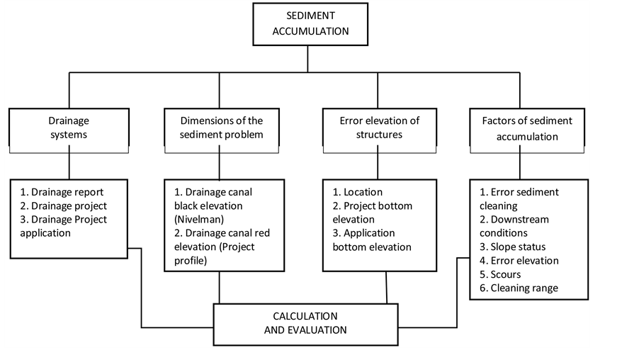
Figure 2. Schematic representation of the method used to determine the accumulation of sediment in drainage channels in the research area.

Table 1. Canal characteristics of D-25 drainage canal group.
paring canal black elevations with the red elevations compiled before from the project and profiles, sediment heights were found. Elevation control works were performed for the years 2010, 2011 and 2012 and one in a year. The extent of work to be undertaken is in most cases determined by visual inspection, followed by detailed measurement of the volume, area, or unit lengths of each task. The most complex estimate is generally that of silt clearance, since owing to variations in the sections of the canal and consequent differences in water velocity, the silt deposited unevenly. The amount of silt deposition in the different stretches of a given canal may quite well differ 3 - 5 times. In order to determine the amount of silt cumulated, a topographical survey is made by taking the sections every 30 or 60 m according to the required degree of precision. With the data obtained the area of the section is calculated. The volume of sediment (VP) for stretch of length, summing the volume of trapezoids in the range cross section gives the total end volume of the cross-section.
 (1)
(1)
where A1 and A2 are transversal section of the sediment and L the length of the section, and therefore for a canal of constant section:
 (2)
(2)
 (3)
(3)
2.2.3. Determination of Art Structures and Elevation Errors
In order to determine the difference between the project and the elevations of applications of art structures (structures constructed on the irrigation and drainage canal) which were made during the leveling made in canals, art structure base elevations (application elevations) were measured. Elevations differences were found by comparing these elevations with the project elevations which were determined from the canal project and the profile. According to project elevation, art structures with differences more than +0.10, −0.10 m are considered to be “bad”. Art structures were also classified as less than −0.10 - −0.49 m, −0.49 m and bigger than +0.10 - +0.49 m and +0.49 m.
2.2.4. Factors Effecting Sediment Accumulation and Determinations of Effecting Groups
The main factors affecting the accumulation of sediment in canals: 1) doing the sediment cleaning on the red elevation (incorrect sediment cleaning); 2) the inadequacy of the downstream conditions; 3) the low slope; 4) art structure elevation errors (especially, art structure built higher than project elevation); 5) doing the sediment cleaning lower than red elevation (scouring), (scouring caused by the other reasons in canals, higher slope etc., were not added into the group); 6) very long sediment cleaning intervals.
In order to investigate these specified factors, downstream conditions and art structure elevation differences were obtained from the results of leveling studies. Slope values were calculated by weighted average method from the project and profiles. The cases when the sediment cleaning is performed on the red elevation were determined with the examination of the profiles in canals, where elevation controls were performed right after mechanical cleaning. Furthermore, scouring is determined with the investigation of canal profiles as a result of elevation control. Information about mechanical sediment cleaning is obtained from DSI 21 Regional Office records. In order to determine the factors effecting sediment accumulation, canals are classified depending on cleaning intervals first (difference between the last cleaning date and leveling work). Then downstream conditions, art structure project and application elevation differences of the canals located in different cleaning intervals were examined and factor or factors effecting sediment accumulation for each canal were determined.
3. Results and Discussion
3.1. According to Drainage Report and Drainage Project
Drainage report, drainage project and situation after the application of drainage system in research area are presented in Table 2. According to the drainage report, drainage canal length is 31 + 155 km, and average main canal depth as 3.50 m, average depth of secondary and tertiary drainage canals as 2.50 m, the base width 2.50 m, gradient slope as 1/2 and slope <0.0004 are recommended for the research area. Even though D-25/2 canal is recommended to be 4 + 066 km according to drainage project, this canal was taken as 1 + 922 km in the project.
Table 2. Qualifications of D-25 drainage canal group to the drainage report, drainage project, and project application.
continued
D-25/3 canal recommended being 4 + 066 km in drainage report is projected as 2 + 543 km, since it is located in the residential area. Even though D-25/5 canal was not recommended in the report, it was projected as 0 + 719 km in project phase. Since D-25/3-d and D-25/3-e canals recommended in the report remain in the residential areas. They were not projected. D-25/1-d canal recommended in the drainage canal is combined with D-25/1 and projected as 2 + 304 km. Canal depths and base widths were significantly decreased in the project phase. Major changes were made in the canal slope in the project according to the report. Total projected canal length is 29 + 367 km. After implementation of the project, canal number and total canal lengths were determined as 18 and 29 + 309 km. respectively. When examined drainage canals of D-25 group are evaluated in terms of their states in the application. It was determined that there are no significant differences in terms of the number of canals or lengths; canals are opened in the application 3 times wider than the values in the project and values in the application are exceeded the values in the drainage report, main canal slope in the project is approximately 1/2 less than the report. As a result of the application, canal length per unit research area is determined as 21.5 m/ha. Art structure identified in the work area after the application is 55 in total containing 5 bridges, 2 passages, 1 galleria and 47 culverts.
3.2. Dimensions of the Sediment Problem
Canal black elevations and sediment heights in D-25 drainage group canals located in the research area were calculated with the leveling works performed during September-October 2010 (before the canals were cleaned). in October 2011 and in 2010-2011 (after all canals were cleaned) and before cleaning of the canals in September 2012. In the study, the results have been shown in Table 3. Classifications of the canals depending on sediment cleaning intervals are presented in Table 4. As a result of the leveling works performed in research area, the study shows that average 0.38 m (at least 0.00m. up to 0.86m) sediment was accumulated in the drainage canals from the years of 2008-2009, when the drainage project was implemented to the fall season of 2010. However, sediment levels in D-25/4, D-25/4-b and D-25/5 canals were calculated as 0.04. 0.10 and 0.00 m. A significant portion of the calculated sediment amount in 2010 was cleaned in the same year. For the research area, total of 35,552 m3 sediment cleaning was programmed in 2010-2011. 35,002 m3 sediment cleaning was performed. Average 8817 m3/ha sediment before cleaning in 2010 (minimum 0.365 m3/ha, maximum 33080 m3/ha), 5940 m3/ha sediment after cleaning (min. 0.24 m3/ha, max. 20163 m3/ha) were calculated. In USA, the North-side Canal Company keeps records of the quality of sediment mechanically removed from drainage canals each year. Some canals are cleaned every year, but others are cleaned only after sediment accumulation seriously restricts flow. This may be every second or third year or longer. An estimate of the quality of sediment deposited canals each year was obtained by averaging the quantities removed mechanically over the past 5 years. This quantity was 295,000 metric tons. This is equivalent to 4.5 metric tons/ha [7] . It was observed after the cleaning that re-sedimentation is high. Average sediment height formed in fall season in 2011 after the cleaning in 2010-2011 in all canals is 0.28 m (min. 0.00 - max. 0.74 m), it was formed in D-25/1-c, D-25/4, D-25/4-b and D-25/5 as 0.00, 0.07, 0.03 and 0.12 m, respectively. Then, even though cleaning wasn’t performed in the canals, sediment height in fall season in 2012 was calculated to increase a little to reach 0.35 m (min 0.15, max 0.79 m). In this case, D-25 group drainage canals are classified in two main groups, one needs to be cleaned every year and second needs to be cleaned every 2 years (Table 4). As it can be seen by examining the table that after sediment cleaning performed in 2010, since accumulation of sediment is in the level which should be cleaned in 13 canals having total length of 22 + 880 km (77.3%). As a result of leveling made in 2011, cleaning period was determined as 1 year. It was determined that there is no need for sediment cleaning in 4 canals with total length of 6 + 016 km (20.6%). As a result of the leveling operation in 2012, it was determined that sediment in cleaning level in all canals was accumulated (average 0.35 m). In this case, in 4 canals which don’t need to be cleaned at
Table 3. Cleaning range, sediment height, and elevation difference of structure of D-25 drainage canal group.
continued
Table 4. Classification to the project status and cleaning range of D-25 drainage canal group.
the end of the first year (total 6 + 026 km length, 20.6%), cleaning interval was determined as 2 years.
3.3. Art Structures and Elevation Errors
Differences determined between the application elevation of art structures in the works made in 2010 and project elevations are shown in Table 3. Classification made according to the differences of art structure, types and project elevations existing in the research area are given in Table 5. When Table 5 is investigated, in 45 out of 55 (81.8%) built art structures, 0.10 m and more differences were observed according to the project elevation. When the distribution of the incorrect art structures were observed as 83.3% numerically, and 93.3% in length of canals, 45 out of total 55 art structures are defective according to art structure number, the rate is 81.8%. Average 0.70 m on project elevation (+) (min. 0.14 - max. 1.61 m), average 0.25 m under project elevation (−) (min −0.11 - max −0.80 m) elevation errors have occurred. Elevation difference in 73.3% (33 of them) of defective art structures is less than 0.10 m, average is 0.40 m (min. 0.10 - max. 1.03 m), less than −0.10 min 26.7% (12 of them) and average is −0.25 m (min. −0.11 - max −0.80). These results show that defective art structures are in almost all canals in D-25 drainage group and their elevations on the project elevation structures are common. Investigation made in canal profiles show that some art structures predicted before are built during the applications. Comparing to 72 art structures in the profiles, 55 art structures were determined.
3.4. Factors Effecting Sediment Accumulation and Factor Groups
Classification made according to the factors causing sediment accumulation and cleaning interval related to D-25 drainage group canals in research area is given in table 6. Sediment accumulation reasons in 13 canals (22 + 668 km, 77.3%) with 1 year cleaning time are incorrect sediment cleaning in 1 canal (1 + 975 km, 6.70%), incorrect sediment cleaning in 11 canals (16 + 001 km, 54.6%) with art structures built in average 0.39 m height (min. 0.11 - max 1.15 m) from the project elevations, incorrect sludge cleanings in 1 canal (4 + 692 km 16.0%), lower slope and art structures being higher than project elevations average of 0.45 m (min. 0.16 - max. 1.03 m).
Prolongation of cleaning interval in 4 canals (6 + 016 km, 20.6%) with 2 years sediment cleaning interval; high canal slopes in 2 canals (1 + 338 km, 4.6%) and cavities as a result of excessive sediment cleaning in 2010, art structure application elevations being higher than average 0.23 m (min. 0.11 - max. 0.38 m) from the project elevations in 2 canals (4 + 678 km, 16%), high slopes and beside the art structures on the project elevations are reasoned to the cavities as a result of art structures under the project elevation. In the observations made in D-25 group, the formation of glide and as a result of this deterioration was determined in slopes of D-25/1-b
Table 5. Classification to the types, number, and elevation faulty of structure in the D-25 drainage canal group.
Table 6. Classification to the factors affecting the sediment accumulation and cleaning range of D-25 drainage canal group.
D-25/1-c, D-25/4-b and D-25/4-d canals. This situation was seen to be as a factor in increasing sediment accumulation.
4. Conclusion and Recommendations
As a general conclusion, there are significant differences between the drainage report with project and the project with application in terms of canal properties. Therefore, facility information form and project area layout plans mostly do not reflect the situation in the application and cause confusion as a result. In terms of cleaning interval processes (although no special study has been done), no difference was observed among main, secondary and tertiary drainage canals. [8] reported that cleaning periods in drainage canals constructed by DSI in Turkey is 4 - 5 year for main canals, 2 - 3 years for secondary canals and 1 - 2 years for tertiary canals. However, this case shows the necessity of performing the evaluation and studies about cleaning period times. While the factors effecting sediment accumulation show variation depending on the special conditions of the drainage systems, giving a canal cleaning time for each drainage network is very difficult. In drainage canals in research area, elevation checking needs to be done every year. However, this is not followed in practice and canal sediment cleanings are not planned according to elevation control results. When leveling and elevation works are performed in canals, canal or canal segments with sediment deposition can be determined clearly. Thus, as a result, unnecessary machine entrance and utilization to the other sections are prevented and improper cavities as a result of incorrect cleanings in canals do not take place.
Important and common elevation errors in art structures are accepted to be one of the important factors preventing the solution of drainage problems. Art structures built above project elevation causes sediment accumulation depending on canal slope, the distance to canal downstream and the degree of elevation differences. Sediment accumulation in the case when the slope is high and art structures are far from the downstream is greater than the canals where the slope is low and the structure is close to the downstream. Art structures built under project elevation causes cavities and changes in canal properties depending on the sediment cleanings and slopes.
Art structures constructed on drainage canals in research area are necessary to be built on the project elevation. Building art structure over the project elevation should be prevented and built ones should be arranged according to project elevation. Studies shows that under some specific conditions, art structures can be built under the project elevation of base elevation (less than 0.50 m), this case might be useful in terms of extending sediment cleaning interval.
Determination of factors effecting sediment accumulation for each canal in research area was tried in the study. These factors are thought to be faulty sediment cleaning, lack of downstream conditions, lower slope (less than 0.0004), elevation errors of art structures and the effect of those together. Lack of downstream, one of these factors, is valid for D-25 canal, which is a main drainage canal of D-25 main drainage group. However, given that each canal has a certain drainage area, almost in every secondary and tertiary canals, downstream conditions caused from the lack of sediment cleaning arise. Therefore, it is necessary to give the priority to main drainage canals in sediment cleanings and performing the cleaning from downstream to upstream.
When the relation between the slope and sediment accumulation is analyzed, it is seen that slopes less than 0.0004 increases sediment accumulation, while slopes bigger than 0.001 in general causes cavities unless structural measures are taken. Since the slope is a factor which is determined by topography, it might not be possible to prevent lower slopes. However, in the possible locations, applying the slope as 0.0004 - 0.001 is useful for decreasing sediment accumulation. In addition, it is necessary to give priority to the canals with lower slopes in sediment cleaning. Due to the topographical structure, [9] reported that various art structures should be projected to not to exceed 6 kg/m2 for maximum drag force or to decrease slopes in the projects in locations with higher slopes.
In the case where canal cleaning is conducted according to leveling studies, it is possible to prevent remaining of sediments or excessive cavities. However, attention should be given to creating possibilities for leveling studies and then to the training of the machine operator.
Art structure elevation errors should definitely be avoided during the project implementation. To accomplish this, field inspections should be increased during project implementation and during the final acceptance. Art structure elevation errors are the most important factor which is the most effective in sediment accumulation and prevents the expected benefit from the sediment cleaning. In particular, errors on the project elevation should definitely be avoided. The effect of these structures, especially in the canals with low slopes, increases more.
References
- Van Schilfgaarde, J. (1971) Drainage Yesterday, Today, and Tomorrow. Proceedings of the ASAE National Drainage Symposium, American Society of Agricultural Engineers, St. Joseph.
- Shinnohammadi, A., Wenberg, R.D., Ritter, W.E. and Wright, E.S. (1995) Effect of Agricultural Drainage on Water Quality in Mid-Atlantic States. Journal of Irrigation and Drainage Engineering, 121, 302-306. http://dx.doi.org/10.1061/(ASCE)0733-9437(1995)121:4(302)
- Mister, D. (2006) Public Drainage in Maryland. In: Needleman, B.A. and Wills, S.A., Eds., Improved Management of Agricultural Drainage Ditches for Water Quality Protection: Field Tour Guide, University of Maryland, College Park.
- State Hydraulic Works (DSI) (2007) Irrigation and Drainage Facilities Operated and Constructed by DSI. Ministry of Environment and Forestry, General Directorate of State Hydraulic Works (DSI), Department of Operation and Maintenance, Ankara.
- State Hydraulic Works (DSI) (2008) Drainage Report of Nazilli Irrigation Area. Ministry of Environment and Forestry, General Directorate of State Hydraulic Works (DSI), Department of Operation and Maintenance, Ankara.
- State Hydraulic Works (DSI) (2005) Records Related to Irrigation Networks in Department of Regional 21. Ministry of Environment and Forestry, Department of Regional 21, State Hydraulic Works (DSI), Department of Operation and Maintenance, Aydın.
- Brown, M.J., Carter, D.L. and Bondurant, J.A. (1974) Sediment in Irrigation and Drainage Waters and Sediment Inputs and Outputs for Two Large Tracts in Southern İdaho. Journal of Environmental Quality, 3, 347-351. http://dx.doi.org/10.2134/jeq1974.00472425000300040010x
- Bekisoglu, Ş. (1995) Solution Methods and Problems Occurring in Irrigation and Drainage Canals. Ministry of Environment and Forestry, General Directorate of State Hydraulic Works (DSI), Department of Operation and Maintenance, Ankara.
- Kızılkaya, T. (1988) Irrigation and Drainage. Ministry of Environment and Forestry, General Directorate of State Hydraulic Works (DSI), Department of Operation and Maintenance, Ankara.