Journal of Software Engineering and Applications
Vol. 5 No. 8 (2012) , Article ID: 21946 , 8 pages DOI:10.4236/jsea.2012.58064
A New Methodology for Process Modeling of Workflows
![]()
Computer Engineering Department, Kuwait University, Kuwait City, Kuwait.
Email: sabah@eng.kuniv.edu.kw, ccc_kwt@hotmail.com, mwaled@gmail.com
Received May 28th, 2012; revised June 30th, 2012; accepted July 11th, 2012
Keywords: Process Specification; Workflow; Conceptual Modeling
ABSTRACT
Workflow-based systems are typically said to lead to better use of staff and better management and productivity. The first phase in building a workflow-based system is capturing the real-world process in a conceptual representation suitable for the following phases of formalization and implementation. The specification may be in text or diagram form or written in a formal language. This paper proposes a flow-based diagrammatic methodology as a tool for workflow specification. The expressiveness of the method is appraised though its ability to capture a workflow-based application. Here we show that the proposed conceptual diagrams are able to express situations arising in practice as an alternative to tools currently used in workflow systems. This is demonstrated by using the proposed methodology to partial build demo systems for two government agencies.
1. Introduction
According to the Workflow Management Coalition (WFMC) [1]Workflow is concerned with the automation of procedures where documents, information or tasks are passed between participants according to a defined set of rules to achieve, or contribute to, an overall business goal. Whilst workflow may be manually organized, in practice most workflow is normally organised within the context of an IT system to provide computerized support for the procedural automation…
Use of workflow-based systems is typically said to lead to better use of staff as well as to better work, management, and productivity [2].
An investigation of current practices in workflow modeling supports the need for further research for improvement in this area. According to [3]Situation [of Workflow technology] is comparable to the early seventies in “databaseland” (ER-model by Chen 76, Relational model by Codd 70). Today’s [2007] situation: We need a conceptual model for WFM (Work flow management]! A unifying process modeling technique!
The first phase in building a workflow-based system is capturing a real-world process in a conceptual representation amenable to formalization and implementation. The representation may be specified in text or diagram form or written in a formal language. “The resulting definition is sometimes called a process model, a process template, process metadata, or a process definition… A process definition normally comprises a number of discrete activity steps, with associated computer and/or human operations and rules governing the progression of the process through the various activity steps.” [1]. A process may also be defined as “[consisting] of a number of tasks that need to be carried out and a set of conditions that determine the order of the task… Task is a logical unit of work that is carried out as a single whole by one resource” [2].
The notion of process is important in the context of workflow and appears in many terms such as business process reengineering, continuous process improvement, and business process management, and many modeling techniques and tools are used in conjunction with process, such as DFD, UML, and Petri nets. For example, [4] used UML activity diagrams as a workflow specification language.
Process modeling techniques are utilized for the purpose of gaining understanding and insight, facilitating analysis, and building a system [3]. An illustration of the relationship between process modeling and actual realization is shown in Figure 1.
This paper deals with this level of description, where the focus is on the methods of specification, the level of a process definition in which the required steps are specified in order of execution, as in a routing definition, and in workflow script, as in the cases of purchase order, insurance claims process, and so forth. The paper proposes

Figure 1. Process modeling techniques are used in many application domains (reformulated from [3]).
a flow-based diagrammatic methodology as a tool for workflow specification. The expressiveness of the method is appraised for its ability to capture workflow-based applications. We show that the proposed diagrams are able to express situations arising in practice as an alternative to tools currently in use for workflow systems.
2. Related Work
Information systems, including software systems, pass through a series of stages in their life cycles. In particular, the requirements phase in software engineering is very rich area, with multiple approaches to workflow specification and business process modeling. Accordingly, this section highlights only a few samples from these approaches in this field.
Process modeling is a central concept in this area. Workflow management (WfM) and business process modeling (BPM) are two ventures in the area of processoriented perspective with different emphases. Processes can be specified using control flow, hierarchical decomposition, and/or generic relations. In this paper our emphasis, without loss of generality, is on workflows.
The notion of workflow is more general than that of a process and consists of a series of connected steps, with an emphasis on the concept of flow.
Process specification is often based on networked activities, objects, transformations, and events utilized in developing more precise and formalized specifications. State charts [5], Petri nets [6], and activity diagrams [7] have been utilized by many studies. Issues of intuitiveness, ease, and rigorousness of semantics are discussed repeatedly in these works.
3. Sample Motivations
While several justifications can be given for venturing into a new modeling method for workflow-based applications, we present in this section, without loss of generality, one aspect that provides some motivations for our work.
In the workflow area, Control flow patterns are abstracted forms of recurring situations related to the ordering of activities and execution in a workflow [4,8,9]. The simplest of these patterns is the sequence pattern, which is an ordered series of activities, with one activity starting after a previous activity has been completed (see Figure 2). Other patterns include parallel, choice, and iteration patterns.
We believe that the sequence pattern embeds ambiguity in many current workflow diagrams in general. Further exposure of conceptual vagueness will be demonstrated by contrasting these workflow diagrams and our methodology using a sample descriptive schema.
According to White [10]The direction of the Sequence Flow arrowheads determines the order of the Sequence. The behavior of this pattern can be described by the use of a conceptual “Token” that travels down a Sequence Flow from the source object to the target object—as shown by the directionality of the arrows. For this pattern, when an activity completes, a Token will travel through the Sequence Flow from that activity to the next activity in the Sequence. There is no conditionality or any other type of control put upon the Token.
The arrow has overlapping semantics: control flow and token flow. Control is usually visualized as a process with input and output. Also, control is described as “the process of monitoring activities to ensure that they are being accomplished as planned and correcting any significant deviation” [11]. In UML, control is visualized in the context of the general notion of behavior, as follows:
Behavior models, in general, determine when other behaviors should start and what their inputs are... In particular, the UML 2 activity models follow traditional control and data flow approaches by initiating sub-behaviors according to when others finish and when inputs are available. It is typical for users of control and data flow to visualize runtime effect by following lines in a diagram from earlier to later end points and to imagine control and data moving along the lines. Consequently a token flow semantics inspired by Petri nets is most intuitive for these users, where “token” is just a general term for control and data values [12].
Notice how the “flow” is qualified by “control and data” and then connected to “token flow” in Petri nets. “Control flow,” or “flow of control,” is typically described as the order in which statements (of an imperative program), processes, operations, etc. are executed—but does “control” flow?
Little has been written about the concept of flow, as discussed in this paper. It is typically described in terms of steps “where each step follows the precedent without delay or gap and ends just before the subsequent step

Figure 2. Sequence—business process diagram.
may begin” [13]. In another perspective and according to [14]The word “flow” sprang up as the word fluxus in Latin, long before many of us can remember. Its root definition has remained intact, with the primary meaning “to move in a (steady) stream.” The cognitive image of a liquid is therefore fused into every metaphor using flow.
Returning to Figure 2, superimposing movement of control and flow of things is conceptually a poor practice. The arrow could represent movement of control, flow of things, or both.
1) Suppose that the token is created at B in Figure 2. Then the first arrow is a pure sequence of control, while the second arrow is both token and control flows.
2) It is possible that A generates tokens that flow to B, but not to C, hence, the B-C arrow is a pure control flow. This is analogous to tying an electrical station to current flow. Station A is turned on first, then B, then C. But this does not necessarily mean that current flows from A to B to C.
3) Conceptually, the token that flows from A to B is not necessarily the same token that flows from B to C. For example, an invoice is sent to B, who creates and sends a money order to C.
This discussion raises the issue of the roles of A, B, and C. It is possible that any of them creates, processes, sends, or receives tokens. In 1) above, B is the creator and sender of tokens, while, say, C is a processor. A is not in the flow path of the tokens. In 2), A is a creator and a processor (e.g., consumer) of tokens, while B and C are not “flow systems” with respect to the tokens.
Control in the workflow sequence pattern seems to indicate activation signals: execute A, then execute B, then execute C. Activation seems to mean doing something with tokens (else, why would tokens flow from A to B to C). Assuming one token, A creates the token, which is somehow processed in B and C. As we stated previously, the superimposing of control and token flows may indicate different semantics, such as B is the creator of the token.
Next we review our proposed flow-based methodology to be contrasted to the workflow diagrams. The described model has been used in many applications [15-17].
4. Flowthing Model
The Flowthing Model (FM) is a uniform method for representing things that flow, called flowthings. Flow in FM refers to the exclusive (i.e., being in one and only one) transformation among six states (also called stages) of transfer, process, create, release, arrive, and accept. All other states are not generic states. For example, we may have stored created flowthings, stored processed flowthings, stored received flowthings, etc. Flowthings can be released but not transferred (e.g., the channel is down), or arrived but not accepted…
The fundamental elements of FM are as follows.
Flowthing: A thing (e.g., information, material) that has the capability of being created, released, transferred, arrived, accepted, and processed while flowing within and between systems.
A flow system: (referred to as flowsystem) is depicted in Figure 3, showing the internal flows of a system with the six stages and the transactions among them.
Spheres and subspheres: Spheres and subspheres are the environments of the flowthing, such as a department, a computer, and a customer, which form the sphere of the flowthing.
Triggering: Triggering is a transformation (denoted by a dashed arrow) from one flow to another, e.g., a flow of electricity triggers a flow of air.
We will use Received as a single stage combining Arrived and Accepted whenever arriving flowthings are always accepted.
5. Example
Consider a complaint handling process as given in [18], where:
• An incoming complaint is recorded
• The client and the department affected are contacted (can be done in parallel)
• Afterwards, the data are gathered and a decision is taken
• Either (1) a compensation payment is made, or (2) a letter is sent.
• Finally, the complaint is filed.
Figure 4 shows modeling of complaint handling as a Petri net, but FM representation, as shown in Figure 5, reveals many flowthings in addition to the complaint. It “starts” when a customer creates a complaint (circle 1) that flows to the complaint department (2). There, it is processed (3) to trigger creation and sending of an initial response to the customer (4). Note that initial response is a different flowthing from the complaint; hence, a dashed arrow indicates a triggering, not a flow. In FM, “flowing
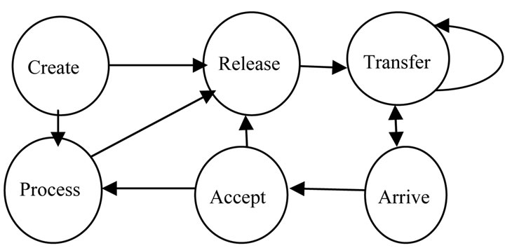
Figure 3. Flowsystem.

Figure 4. Modeling of complaint handling as a Petri net [17].
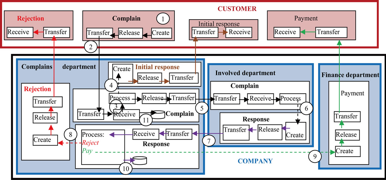
Figure 5. FM representation of the complaint handling process.
things” do not flow within each other. The design is like the blueprint of a building where lines of electrical flow may trigger, but never run in, a flow of water.
In Figure 5, the complaint also flows (5) to the involved department, which processes the complaint and creates a response to it (6). Notice the continuity of several processes with uninterrupted connection and succession, as in the production of film and television, where a script maintains continuity across shots and throughout the production process with contiguous events “in the same universe.” Compare this with the sketches and gaps in Figure 4. For example, the objects of record are complaints, pay is an action related to money, then file is again related to complaints. Note the conceptual discontinuity: the complaint is recorded, client and department are contacted, then something is collected—what? Where are the flows of the department’s response, the initial response to client, the rejection letter, payment, … and complaints? All are shuffled into one type of arrow. Who is doing the recording, collecting, assessing, and so on? Usually this is the job of the complaints department, while payment is done by the finance department. All these semantics are implicit and may be understood differently.
Continuing with Figure 5, the involved department sends (circle 7) its response to the complaint department, which processes the case and triggers (8) the creation and sending of a rejection letter. Or it triggers (9) the finance department to create and send a payment to the customer. The complaint and the processed response are also filed (10 and 11).
Sections 6 and 7 show use of the flowthing model with real-life examples of document workflow in a government agency.
6. Experimental System I: Document Flow System
This system is characterized by two main processes, one for documents originating internally to flow outside the agency, and one for documents entering the agency from outside sources to be processed internally. This system is depicted in Figure 6.
In the figure, an employee (1) creates a document, copies it, then releases it to a messenger. The messenger transfers (2) the document to a secretary, who saves a copy before releasing the document to the director (3). After the director signs the document, it returns to the
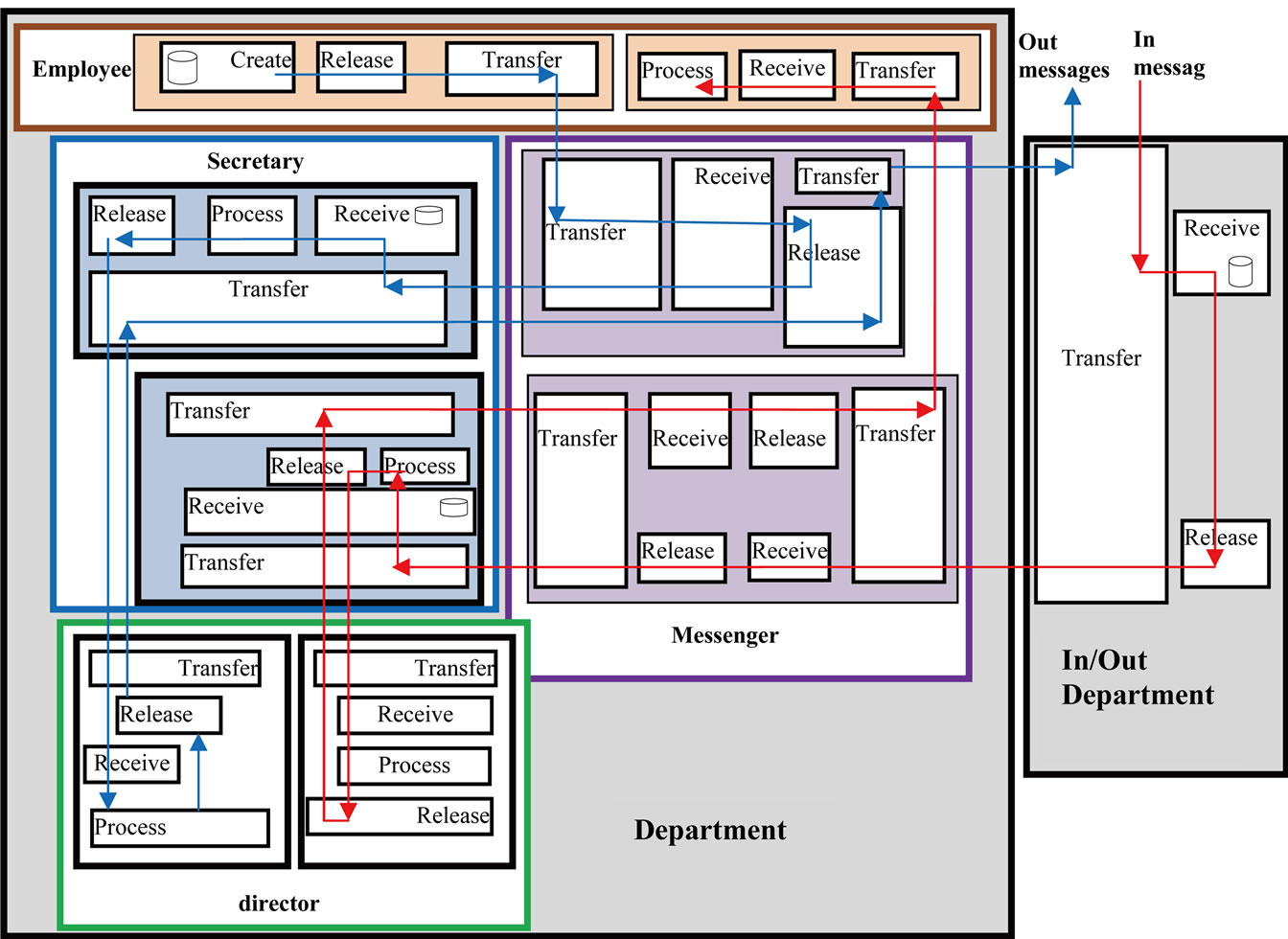
Figure 6. FM description of the in/out message system
secretary, then the messenger transfers it to the in/out department (4). An electronic copy of the document is saved and sent to the right destination.
Incoming documents flow through a similar path (5)- (10) until reaching an employee for processing.
Figure 7 shows the main screen in the FM demo system. It includes the six stages activated according to the corresponding sphere, e.g., the messenger does not create any document, list all lists all documents, e.g., an employee sees all her documents that are in the created stage, processed stage...
Suppose that an employee activates Create. Then, the page shown in Figure 8(a) appears, allowing the employee either to create a new document or to list current created documents in her sphere. Suppose she selects LIST; all her created documents then appear, as shown in Figure 8(b). Selecting New in Figure 8(a) produces the page shown in Figure 8(c).
In Figure 8(c), Find File refers to a file that includes the new document. A file is then allocated in a similar manner to attaching a file to email. “Body” in Figure 8(c) indicates that the actual document is not an electronic file, and the system’s role would be to monitor the flow of this physical document among stages and spheres. “Add Info” opens a page (not shown) with information about the document, with the capability of inserting new
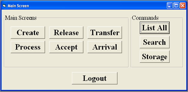
Figure 7. Main screen for FM system.
information. “To Release” and “To Process” refer to moving the document to the release and process stages, respectively.
The remaining stages of the FM system will be discussed in experimental system II.
7. Experimental System II: Case-Flow System
This system models the current workflow of legal cases in the General Directorate of Investigation. As shown in Figure 9, the flow model starts with creation of a case in the police station by an investigator (circle 1). As in the previous experiment, creating a case involves many selections and ranges from simple cases in electronic files to physical files, or both.
 (a)
(a)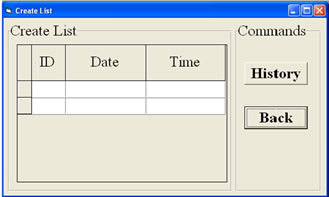 (b)
(b) (c)
(c)
Figure 8. Pages for create in main menu.

Figure 9. FM description of the system of general directorate of investigation.
The most important data are the case number, information about the accused and the victim, case type, and date. The investigator writes a memorandum about the results of the investigation and his opinion of the case, and a file is opened containing a case number, name of the police station as well some ID documents, and medical reports if they exist. The file then flows electronically or physically to the secretary of the station (2), where it may be returned to the investigator, e.g., missing signature, incomplete information, etc. The case then flows (3) to a messenger (4) to be received by the secretary of the chief investigator’s office (5) for review by the chief investigator himself (7) and (8). The chief investigator then sends the file back to his secretary. At this point the case is given to a messenger (6), either to be sent back (9) or to progress to the Governorate investigation manger at the next level (10).
This cycle of receiving the case, reviewing, and sending through a messenger is repeated when the case file flows through the offices of the Chief Prosecutor, General Manager of Prosecutions, and General Directorate of Investigation. Finally, the case is given to a prosecutor (25), the complete file is processed, and a decision is issued (26).
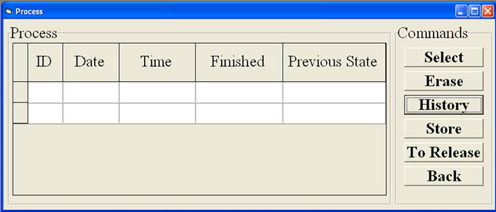
The main entry menu for the case-flow system is as discussed in the previous section using Figure 7. In this system we explain other stages of the FM system. Suppose that the user (e.g., the investigator, secretary, messenger, director, or manager) selects Process in Figure 7. The page shown in Figure 10(a) appears, with a list of cases currently in the process stage of that sphere. One case in the list can be selected for further processing. In Figure 10(b), the user can select from three processes, say, signing, translating, and authentication. Alternatively, in Figure 10(a), the user can get the history of the case, erase it, or send it to the released state. If released, it will not appear in the list of cases in Figure 10(a). Returning to the main menu and selecting Release opens a list of the released cases, including the one just moved from the process stage. Similarly, cases can be removed to the transfer stage. Note that the release stage includes cases that are approved by the user to be released, but the user has not yet decided when to transfer them outside his/her sphere. The transfer stage includes cases that are actually transferred by the user. In spite of this, cases may still be in the transfer stage for some reason, such as waiting for the communication channel to be available. Or a case can be waiting in the out tray to be picked up by an internal mailman (messenger). Figure 11(a) shows the transfer stage page. Also, Arriving cases (Figure 11(b)) appear when Arrive is selected from the main menu. For example, a manager starts her day by determining what new cases have arrived in her desk that day. She can reject, erase, accept… cases accordingly.
 (a)
(a)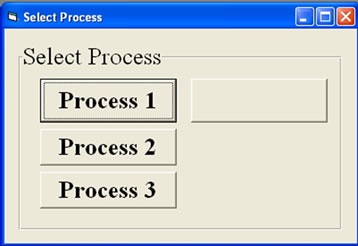 (b)
(b)
Figure 10. Some pages in the process stage.
 (a)
(a)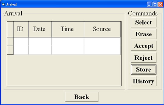 (b)
(b)
Figure 11. Some pages of the transfer and arrival stages.
Note that the FM system covers both electro and physical flows. For example, the delivery person (messenger) performs the physical process of moving documents from one place to another. The FM system monitors such movement by recording information about the delivery process. It is possible that a manager knows from the system that a case is being transferred to him; however, the actual messenger has not yet reached his sphere.
In FM, flow-based specification is uniformly aligned with implementation of the system. The flow of cases in Figure 9 is a mirror of the implementation of various pages presented to the user. By contrast, other specifications of requirements methodologies, say, the Petri net description of Figure 4 and its implementation as a system, present completely different languages and notations.
8. Conclusions
This paper proposes a flow-based diagrammatic methodology as a tool for workflow specification. The expressiveness of the method is appraised though its ability to capture workflow-based applications. The methodology has been applied to two real-life systems. The results show that the proposed conceptual diagrams are able to express situations arising in practice as an alternative to tools currently used in workflow systems.
Current work in this area involves building of an actual system utilizing the new methodology to further explore the features of FM-based modeling.
REFERENCES
- D. Hollingsworth, “The Workflow Reference Model, Workflow Management Coalition (WFMC),” Document No. TC00-1003, No. 1.1, 1995. http://www.wfmc.org/Download-document/TC00-1003-The-Workflow-Reference-Model.html
- W. van der Aalst and K. van Hee, “Workflow Management: Models, Methods, and Systems,” MIT Press, Cambridge, 2004.
- Sistemi Informatici Supporto Alle Decisioni, “Introduction to Workflow,” AA 2006-2007. http://www.di.unipi.it/~giangi/CORSI/SISD/Lezioni/WFM1.pdf
- M. Dumas and A. H. M. ter Hofstede, “UML Activity Diagrams as a Workflow Specification Language,” In: M. Gogolla and C. Kobryn, Eds., UML 2001—The Unified Modeling Language, 4th International Conference, Toronto, 1-5 October 2001.
- P. Muth, D. Wodtke, J. Weissenfels, A. K. Dittrich and G. Weikum, “From Centralized Workflow Specification to Distributed Workflow Execution,” Journal of Intelligent Information Systems, Vol. 10, No. 2, 1998, pp. 159-184. doi:10.1023/A:1008608810770
- W. M. P. van der Aalst, “The Application of Petri Nets to Workflow Management,” The Journal of Circuits, Systems and Computers, Vol. 8, No. 1, 1998, pp. 21-66. doi:10.1142/S0218126698000043
- M. Schader and A. Korthaus, “Modeling Business Processes as Part of the BOOSTER Approach to Business Object-Oriented Systems Development Based on UML,” Proceedings of the 2nd International Enterprise Distributed Object Computing Workshop, IEEE Press, New York, 1998.
- W. M. P. van der Aalst, A. P. Barros, A. H. M. ter Hofstede and B. Kiepuszewski, “Advanced Workflow Patterns,” Proceedings of the 5th IFCIS International Conference on Cooperative Information Systems, Eilat, 6-8 September 2000.
- W. M. P. van der Aalst, A. H. M. ter Hofstede, B. Kiepuszewski and A. Barros, “Work-Flow Patterns,” Technical Report WP 47, BETA Research Institute, 2000. http://tmitwww.tm.tue.nl/research/patterns
- S. A. White, “Process Modeling Notations and Workflow Patterns,” BPTrends, 2004. http://www.omg.org/bp-corner/bp-files/Process_Modeling_Notations.pdf
- R. Robbins and K. Coulter, “Management,” Prentice Hall, Upper Saddle River, 2001.
- C. Bock, “UML 2 Activity and Action Models,” Journal of Object Technology, Vol. 2, No. 4, 2003, pp. 43-53. doi:10.5381/jot.2003.2.4.c3
- Wikipedia, “Workflow,” 2012. http://en.wikipedia.org/wiki/Workflow
- J. D. Casni, “‘Flow’ Hits Its Peak,” 2005. http://metaphorobservatory.blogspot.com/2005/11/flow-hits-its-peak.html
- S. Al-Fedaghi, “Scrutinizing the Rule: Privacy Realization in HIPAA,” International Journal of Healthcare Information Systems and Informatics (IJHISI), Vol. 3, No. 2, 2008, pp. 32-47. doi:10.4018/jhisi.2008040104
- S. Al-Fedaghi, “Software Engineering Interpretation of Information Processing Regulations,” IEEE 32nd Annual International Computer Software and Applications Conference, Turku, 28 July-1 August, 2008.
- S. Al-Fedaghi, “Personal Information Flow Model for P3P,” W3C Workshop on Languages for Privacy Policy Negotiation and Semantics-Driven Enforcement, Ispra, 17-18 October 2006.
- W. van der Aalst and K. van Hee, “Workflow: Models, Methods, and Systems,” MIT Press, Cambridge, 2004. http://www.di.unipi.it/~giangi/CORSI/SISD/Lezioni/WFModel.pdf