Engineering
Vol.5 No.5(2013), Article ID:31693,9 pages DOI:10.4236/eng.2013.55058
Testing of the Ultra-Micro Gas Turbine Devices (1 - 10 kW) for Portable Power Generation at University of Roma 1: First Tests Results
Department of Mechanical and Aerospace Engineering, Sapienza—University of Roma, Roma, Italy
Email: roberto.capata@uniroma1.it, alfonso.calabria@uniroma1.it, Mario.diveroli@uniroma1.it, gianluca.pepe@uniroma1.it
Copyright © 2013 Alfonso Calabria et al. This is an open access article distributed under the Creative Commons Attribution License, which permits unrestricted use, distribution, and reproduction in any medium, provided the original work is properly cited.
Received February 22, 2013; revised March 29, 2013; accepted April 6, 2013
Keywords: Ultra-Micro Components; Gas Turbine; Radial Compressor; Combustion Chamber
ABSTRACT
The ever increasing development of portable electronics has led to a higher demand for compact and reliable power sources. Significant resources are being presently dedicated to the study of micro machined gas turbines, because of their remarkable power density. The paper reports the procedures and the results of a series of tests conducted at the Department of Mechanical & Aerospace Engineering of University of Roma 1, to obtain the map of an ultra-micro gas turbine device, and the head losses and the combustion efficiency of the corresponding ultra-micro combustion chamber, fed by a mixture of butane and propane. This work is a part of a research aimed at the conception, design and prototyping of an ultra-micro thermo-electrical device for portable power generation. The novelty of the research consists in the fact that the thermal engine is a (ultra-micro) gas turbine set. In a subsequent stage, several different configurations have been assessed to select the most proper geometry and structural characteristics of the most relevant components (radial compressor, radial turbine, combustion chamber, electric motor and generator, bearings, regenerative heat exchanger).
1. Introduction
Although the quest for ultra-micro (and even nano-micro) portable power supply systems is over a decade old, and since the mid 90’s several research teams all around the world have been actively involved in this very specialist field, today there are only a few and incomplete prototypes of such devices, most of them failing to reach acceptable performance. The fundamental idea is that of powering a micro-scale electric generator with a thermal device that can run on a generally available fuel (kerosene, propane/butane mixtures, methane, hydrogen, etc.), so that the user can avoid carrying a quite heavy battery package. Reciprocating engines being unfeasible at these small scales, the use of gas turbine micro-plants has been investigated. Major advances have been made in the US (MIT, Stanford [1,2]), in Japan [3] in Belgium (Leuven [4]) and in Italy, University of Roma 1 [5,6] and the work at ONERA laboratories in France.
All teams have until now adopted the same configuration as the one used in “large scale” gas turbines. There are other configurationally variations of this cycle, but for very small units, the simple Braytoncycle is the only one considered to date. For thermo-fluid dynamic reasons, the efficiency of a gas turbine set can be increased by either one of the following actions:
• Increase the maximum allowable combustion gas temperature, TIT;
• Correspondingly increase the pressure ratio of the compressor C;
• Optimize the regeneration (i.e., the amount of heat subtracted to the hot gases and delivered to the cold compressed air before CC) in the heat exchanger R.
The increase of the TIT (turbine inlet temperature) is limited solely by technological reasons: the blades of the turbine are usually made of special alloys that can sustain continued operation at a TIT of about 1300 K. For higher gas temperatures, internally cooled blades have been employed, or alternatively ceramic materials have been used to manufacture the blades. In ultra-small GT, blade cooling is technically impossible, while ceramics have demonstrated to be unsuitable for the extremely high rotational speeds required by these devices. The pressure ratio of the radial compressor is basically dictated by its rotational speed U, to whose square the specific work of the compressor (and hence the pressure ratio) is proportional. Thus, a higher β require higher U, and this poses both fluid dynamic (losses, leakage, efficiency) and structural (creep, vibrations) problems of difficult solution.
2. Preliminary Considerations on the Tests Campaign
The Experimental texts reported in this paper are a direct consequence of two projects being developed at the Department of Mechanical and Aerospace Engineering of Roma 1. In the first case, evaluation tests on the JETCAT model fall in “SEALAB” project for the construction of a high-performance marine vehicle. In the second case, the thermal mapping of combustion chamber and its specific consumption, within the project PNR 714 with Italian Army Head Quarter for the realization of a portable device. Both devices, then, could be used, once a possible connection with inverter has been realized, as a rangeextender on hybrid vehicles, UAVs or boats.
3. The Jetcat Gas Turbine (GT) Device
The Graupner/Jetcat turbo-prop engine represents a successful combination of high power reserves and hightech engineering. In the world of full-size aviation most types of propeller-driven machine have already been converted to turbo-prop power, but the engine relentless progresses has only just begun in the model aviation arena. As the name indicates, the turbo-prop engine—its full name is a turbo-jet propeller engine—comprises a gas turbine driving an airscrew. The primary advantages of the turbo-prop in full-size aviation lie in its compact shape and its economy and reliability at speeds below 700 km/hr. The basic design and method of working of the new model engine correspond quite closely to those of the full-size power plants. The principle is very easy to understand: it is simply a matter of finding a suitable method of converting the high power of the turbine engine into usable shaft power. However, this is not necessarily a straightforward matter, especially when you consider the very high turbine rotational speed. In the engine presented here the rotational speed is reduced in two stages: the first is a gas reduction, the second a geared reduction. This means that when the turbine is running, the gas flow from the core engine drives a turbine wheel which is mounted on a second shaft. This second shaft is mechanically completely independent of the rotor of the base engine and not connected to it; it receives its power solely from the kinetic energy of the exhaust gas flow. The secondary shaft directly drives a gearbox designed to cope with high rotational speeds, and this in turn reduces the speed to a value suitable for a propeller. The gearbox is fitted with an integral axial fan which provides the necessary airflow for cooling the components exposed at high temperature. Another completely new feature of the engine is the electronic control system, which processes the speed information derived from both shafts, primary and secondary. This simply means that the pilot can concentrate entirely on flying, while the complex engine management processes are carried out fully electronically. The reduction gearbox is a specially developed planetary gear design, highly efficient and very compact. Whenever a new kind of power system concept is introduced, the model flyer is obliged to immerse himself in the subject in order to gain the necessary expertise, and this certainly applies to turbines. However, once the operator has become familiar with the procedure, it is actually simpler to handle a turbine installed in a model aircraft than to operate a piston engine: only a single radio control system channel is required to control the engine, and starting preparations for the engine simply boil down to filling the fuel tank and a small auxiliary gas tank required to start the turbine. The engine starts at the press of a button from the transmitter, and the entire starting process runs automatically, controlled by the gas turbine on-board electronics (ECU). Initially the integral electric motor accelerates the turbine to a speed of around 6000 rpm, then the auxiliary gas supply is opened and the gas is ignited in the turbine’s combustor. The gas turbine then continues to accelerate until the burning gas overtakes the starter motor’s speed; the motor then disengages, and the turbine continues to accelerate until it reaches a speed high enough to support running on kerosene. Once the start-up process is completed successfully, the ECU sets a stable idle speed before transferring control to the pilot. After the flight the pilot reduces engine speed in the usual way, then—using the same channel—he initiates the power-down process, which is again entirely automatic, under the control of the on-board electronics: first combustion is halted, then the starter motor is switched on again to push fresh air through the turbine until the internal temperature has fallen down to below 100˚C. An LED in the case of model lights up to indicate that this cooling-off phase is complete, at which point the receiving system can safely be switched off.
The characteristics of the GT device are reported in the Table 1, while in Figure 1 is shown the device.
3.1. Jetcat Fuel Supply System
The Jetcat engine can use deodorized kerosene, 1-K kerosene or Jet-A1 as fuel. Fuel must be mixed with 5% synthetic turbine oil. Jetcat itself recommends Aeroshell 500 turbine oil although any turbine oil that conforms to
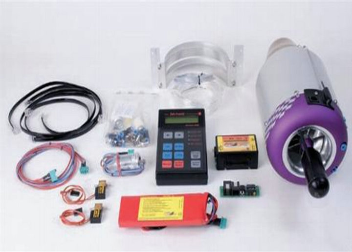
Figure 1. Jetcat model and accessories.
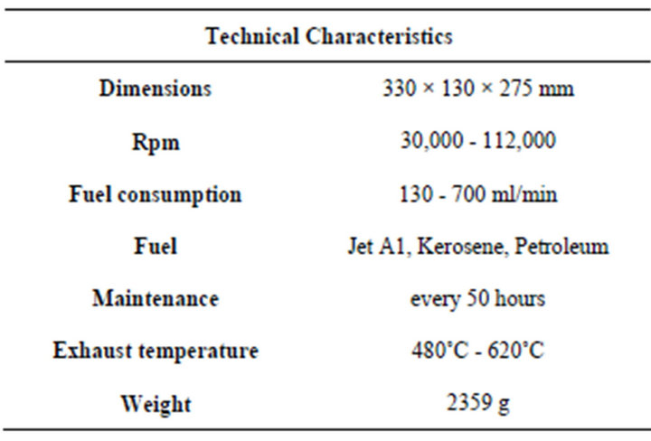
Table 1. GT published nameplate.
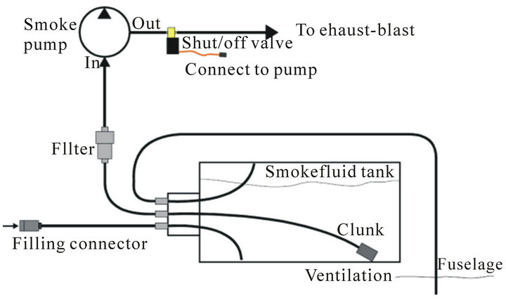
MS23699 standards will work. The input and output fuel piping must be connected to the electronic shut-off valve as shows in Figures 2 and 3.
The tube from the pump, called “fuel in”, is direct to the heat shrink pipe covered coil. The tube to the engine, “fuel out”, is close to the edge of the valve. The engine is equipped with a smaller valve (brass/plastic body). The manufacturer recommends checking and clean the fuel filters every ten (10) flights/runs. When the engine runs at full power, the control unit ECU checks the fuel line from the pump to the engine. If there is a large quantity of air bubbles flowing with the fuel, probably due to a restriction in the fuel system or an air leak in a fitting, the system automatic shutdown. It is important not to over-pressurize the kerosene tanks and the kerosene shut off valve during refuelling operations. To prime the fuel pump and fuel lines (or for fuel pump test purposes), it is necessary to open the fuel shutoff valve and run the fuel pump manually.
Pump/Purge fuel operation allows the fuel pump to operate without the turbine running. However, if the fuel feed line is not removed from the turbine during this procedure; it will become flooded by fuel. When this occurs,
 (a)
(a) (b)
(b)
Figure 2. Jetcat fuel system and Jetcat connections points.
the next turbine start will be characterized by a higher fuel consumption.
Figure 2 also shows the additional measurement points used to map the compressor. The housing for the additional instruments has been created ad hoc, on the case of the distributor and the return channel.
The inlet conditions were considered those of the environment. In this case, the measure of temperature and ambient pressure is repeated many times using commercial tools not overly sophisticated. However, the value of the ambient temperature has fluctuated between 12 and 17˚C and the pressure between 100.67 and 102.1 kPa. Regarding the operating speed and fuel consumption, this derives from the power control software using turbine ECU.
The devices used were a pressure sensor and two thermocouples Thanks to these measures we could compute the compressor pressure ratio and calculate, once known the discharge temperature, the efficiency for various speeds. These results are reported in Figures 4-7.
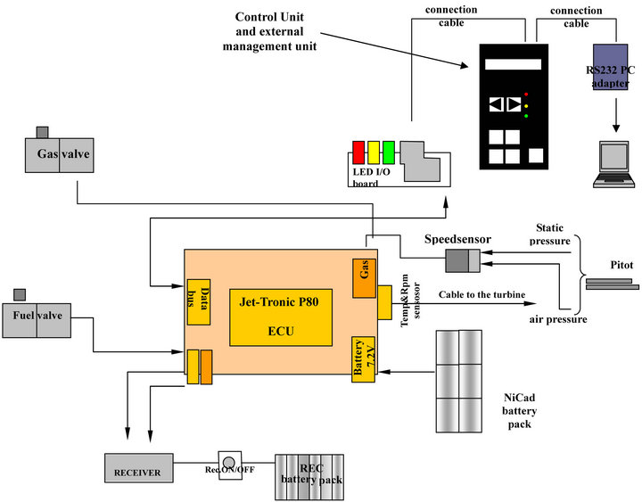
Figure 3. Jetcat connection arrangement and measurements standard devices supplied devices.
After the turbine has ignited, the starter motor further accelerates the turbine. At approximately 5000 RPM, the fuel pump is automatically started at its minimum power by the ECU. Beginning from this first pump start voltage, the fuel flow is then slowly increased by increasing the pump voltage.
The initial pump voltage that is supplied for the pump immediately after ignition has been adjusted by the factory. If the fuel pump is changed or after several turbine runs the pump is breaking in thus delivering too much fuel at start-up causing long flames behind the turbine exhaust, it might be necessary to readjust the pump start voltage. Table 2 reports the characteristics of the tests carried on the Jetcat GT device.
At the end of the tests it can establish that the compressor maximum pressure ratio is approximately equal to 3 for a mass flow rate of 0.30 kg/s. The efficiency of the compressor varies between 0.52 and 0.77.
Consequently the fuel consumption varies within 0.0015 to 0.010 kg/s. The turbine inlet temperature (TIT) varies within 858 to 1137 K.
4. The Ultra Micro Gas Turbine Generator (UMGTG) at University of Roma 1 (UDR1)
The UMGTG-UDR1 device consists of the following fundamental components: compressor C, turbine T, com-
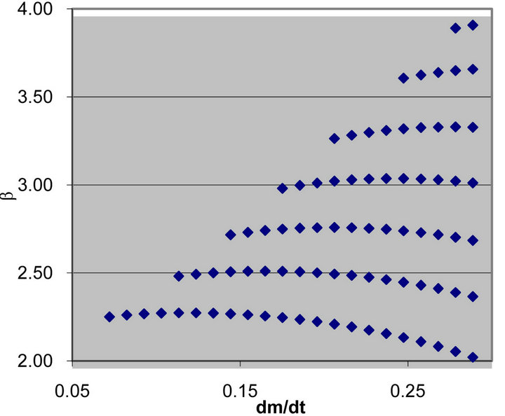
Figure 4. Compressorpressure ratio in function ofcompressor inlet mass flow rate.
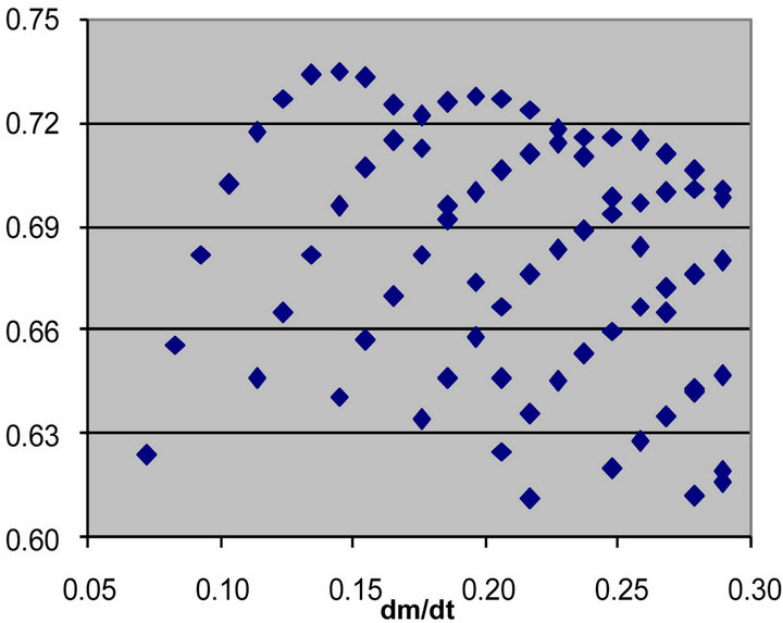
Figure 5. Compressor efficiency in function of compressor inlet mass flow rate.
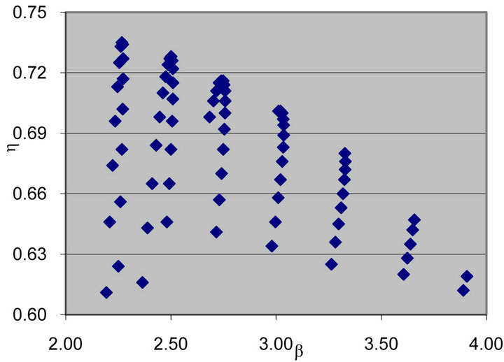
Figure 6. Compressor efficiency infunction of β.
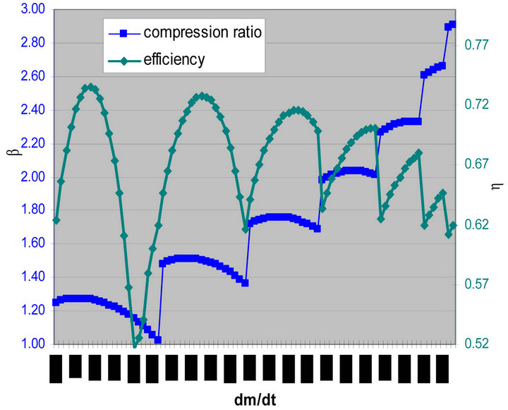
Figure 7. Compressor efficiency and b in function of compressor inlet mass flow rate.
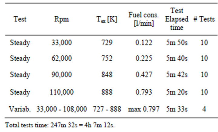
Table 2. Tests main data.
bustion chamber CC, regenerator R, electrical motor EM, electrical generator EG, electronic control unit ECU, and case. External to the case, but of course properly connected to it, is the fuel tank assembly.
The operation of the UMGTG-UDR1 [5,6] is as follows:
• The compressor C pressurizes a stream of air;
• At the exit of compressor, the air stream is preheated in a regenerator;
• The preheated compressed air is then channelled into a combustor CC into which a suitable fuel is injected;
• The hot combustion gases are expanded through the turbine;
• The turbine powers the electric motor/generator (a dual effect engine);
The particulars of the UMGTG device are:
• The generation of 500 - 2000 W or less of electrical power by means of a thermo-electrical conversion device of a sufficiently small size to be considered “portable”;
• The internal arrangement of the device, in which a ultra-micro gas turbine plant provides the energy conversion from fuel to electrical power.
The packaging of said device is composed of several operative zones, each one designed to achieve the best possible performance and also designed in such a way that it might be built using commercially available components. The scope of the research is to provide electric power in a standalone operational mode, with limited fuel consumption and using a very compact device with a total length 0.334 m, width 0.184 m and height of 0.190 m and an occupied volume of 0.012 m3. The prototype and the proposal assembled device are shown in Figure 8.
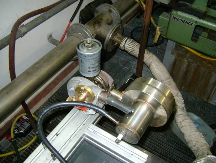

Figure 8. The proposed device and the prototype assembled at laboratory. The indicated dimensions are in mm.
It can be noticed that regeneration takes place inside the combustion chamber, thanks its particular architecture that will be discussed as follows. In Figure 9 the schematic representation of the UMGTG UDR1 cycle.
4.1. The Combustion Chamber Tests
As explained in the previous sub-section, the combustion chamber is an original design by the Mechanical and Aerospace Engineering Department of the University of Roma 1 Sapienza. A first order thermo-fluid-dynamic simulation has been carried out [7], and a more detailed study is in progress, to assess the attainment of a satisfactory thermal field for the liner and the completeness of combustion. A series of tests [5,6] provided the temperature map of the CC for a more exact analysis of the thermal flows and for experimentally validating the CFD results. A hole drilled on the top surface of the combustion chamber is the bay for a spark plug to activate the ignition of the (non pre-mixed) air-fuel mixture. On the cylindrical external surface, the second hole from the bottom is the compressor air inlet (B) the air flows through the spiralling duct and is pre-heated, and enters the combustion chamber from the upper side. The combustion air is injected with an intense swirl motion, in order to enhance mixing with the fuel that is in turn injected from a second port in the upper half of the cylinder. The combustion progresses and the exhausted gases exit from a port located on the opposite (bottom) side of the chamber and before being exhausted flow through a cylindrical shell around the spiralling air inlet to provide further preheating. Further developments of the combustion chamber are being explored, and include several possibilities: from an increased number of spiralling turns of a smaller cross area, to grooved internal surfaces. The scope of such improvements is to enhance the heat exchange and achieve a lower fuel consumption and a higher overall efficiency [8]. The option of inserting a secondary air pre-heater (thus implementing in effect a two-zone combustion) is also being considered. The inner diameter of the assembled combustion chamber is 22 mm, its outer diameter 42 mm and the overall height is 130 mm (Figure 10)
A fundamental step in the test of the combustion chamber is the temperature mapping of its surface. In particular, the measurements have been carried out at the following points (Figure 11):
• Inlet compressor air in the preheating zone;
• External wall of the inner cylinder;
• External wall of the outer cylinder;
• Exhaust gas volute wall.
The first part of the tests was devoted to the evaluation of the ignition time. Priming the combustion chamber is quite difficult when the inner chamber is still cold, and it
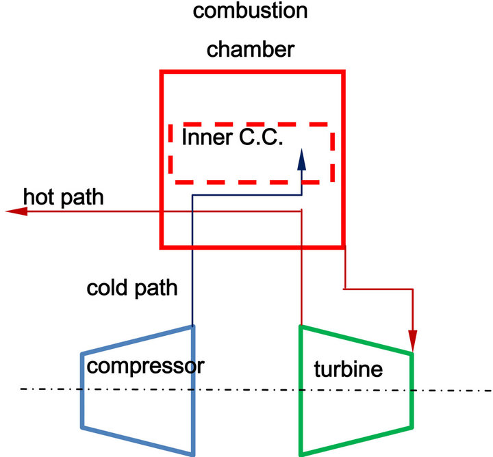
Figure 9. Schematic of UMGTGregenerated cycle.
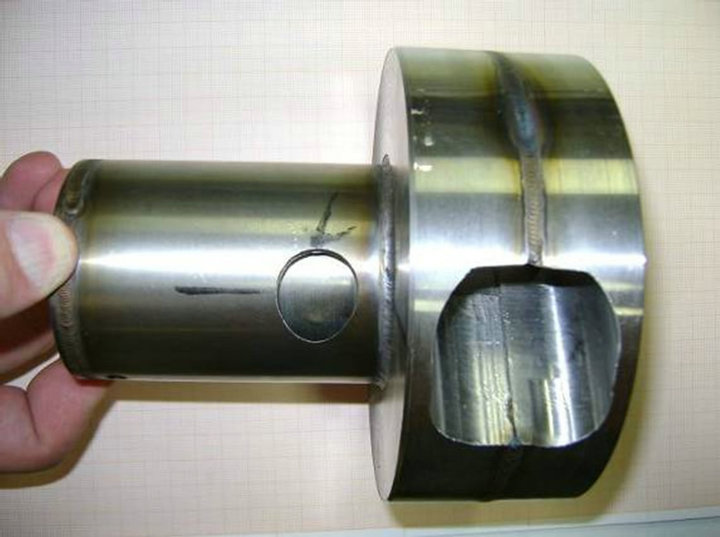
Figure 10. The tested prototype of the combustion chamber.
required about 30 seconds. Once the chamber has been heated, the combustion is almost instantaneous. The following step has been the verification of combustion stability. These tests have been repeated with an interval between successive ignitions of three to five minutes. During the tests, attempts were made to regulate the air/fuel mixture in such a way as to establish different combustion regimes. In particular, after a first warm-up transient, a “complete” combustion was attained, with a typical blue colour of the flame that indicates the absence of unburned fractions. This combustion regime is maintained for about 10 - 15 minutes (see Table 3). We notice that, at the minimal variation of the fuel flow rate or inlet air, the flame presents unburned fractions again. The tests have underlined how the stability is obtained but the efficiency changes rapidly, when varying the air to fuel ratio.
4.2. Tests Results
After the ignition protocol was satisfactorily validated, the next series of tests were devoted to the measurement of the temperature at points A, B, C, D, E, F on the external wall of the chamber:
• In section D (see Figure 11), the values of temperature are comprised between 1173 K and 1288 K. The discrepancies are assumed to be due to the flow unsteadiness. A consistent correlation was observed between higher temperatures and higher combustion
Figure 11. Sketch of the flows in the CC.
Table 3. Ignition time.
efficiency conditions. In particular the temperature of 1288 K was measured keeping the K-thermocouple directly immersed in the exhaust gas (blue flame) for approximately 1 minute;
• On the external chamber wall (surface C in Figure 11), the measured temperatures varied between 473 K (200˚C) on the top cover (cold zone) and 873 K (600˚C) on the bottom one (hot zone). The cooler compressor air that flushes the preheating section exert a moderating effect on the wall temperature;
• The temperature measurement on the surface of the inner cylinder can be only performed in the immediate vicinity of the compressor air inlet section (point E, Figure 11). The amount of preheating obtained (a temperature increase of about 400 K) is reasonable in view of the following considerations:
• The temperature is relative to a wall on which “cold” (~310 K) compressed air impinges;
• The wall temperature of the operational machine is higher;
• The air “cup” temperature in the entry portion of the channel is lower than the average wall temperature of the inner cylinder.
• The above measurements confirm that the CC attains a regeneration degree (at least) equal to the one assumed in the preliminary design.
• Moreover, in the design phase a TIT of 1300 K was assumed, and the tests have measured a TIT of 1288 K, for all practical purposes sufficiently close to the design value, especially discounting the rather rough experimental conditions. These considerations lead to the conclusion that the design of CC was correct, in that the device operates at its foreseen design point. The results of the thermal test of the chamber are reported in Table 4.
5. Tests Measure Protocol
In this Section the testing procedures has been described. The campaign has been carried out, adopting the following procedures:
1) Definition of the acquisition time
This parameter has been defined according to the type of the required measures. It has been focused on 3 operational mode:
• Starter;
• Transitory;
• Steady condition.
For each mode it has been chosen the “characteristic” time of acquisition, reported in Table 5.
2) Frequency of acquisition
Such frequency has been varied within the sensitivity range of the instrument. The higher value is needed to acquire the higher frequencies in the transitory. So we
Table 4. Combustion chamber thermal field.
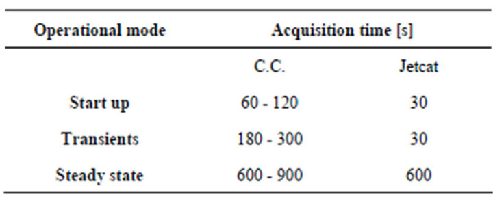
Table 5. acquisition time.
adopt 3 working frequency for each operational mode:
• 10 Hz (steady state);
• 100 Hz (start);
• 1000 Hz (transients).
3) Environment parameters
The external environment temperature has been measured, regularly, every 15 minutes during the tests. At the scope a bulb thermometer has been used (sensibility of 0.5˚C, error of ±0.2˚C).
4) Instruments nameplate
a) Thermocouple TC9M-A-1-K-C-L-K for high temperature:
It is a sensor with special coating. Temperature measuring range is within 100˚C to 1600˚C, with protection sheath of recrystallised alumina KER 710 (C-799) tube and special platinum thimble;
b) Thermocouple TC5-m-1-K-5-F-E-B-3:
Typical Fe-Co device. Material AISI 16 stainless steel with measuring range of 0˚C to 600˚C;
c) Pressure gauge type TK-E-1-E-BO3U-M-V:
Measuring range of 0 to 3 bar.
5) Pre treatment and normalization of the data
All data has been collected via PC and then has been so processed:
a) Gauss Analysis of the deviations: mean values, mode, median and standard deviation have been automatically calculated by the software of the used acquisition card;
b) Filtering: each data that exceeded 3s has been individually controlled, and neglected like spur if possible acquisition errors were not found;
c) Normalization: the values are standardized in order to control that their distribution followed a Gaussiantype;
4) Presentation: for each measure, the relative standard deviation and the medium value has been supplied (“rms”).
6) Tests Elapsed Time
Regarding the hot tests on the combustion chamber, the tests have been subdivided in several sessions, with effective actual time for every session between 2 - 3 hours.
In the same manner, the tests have been subdivided in several sessions, with effective actual time for every session between 4 - 5 hours.
6. Future Developments and Conclusions
The CC has been tested separately and now the device has been assembled for the final tests that are going to be carried out. The second step will be the deep study of the ignition procedure, to compute and measure all turbomachinery characteristics for the UDR1 prototype and for the Jetcat GT. These final tests should indicate the future possible optimization action to produce the final device (for the UMGTG UDR1), ready for a pre-commercialization, while, for what concern the 5 kW Jetcat GT, the tests would indicate how to optimize the device to reduce the fuel consumption and increase the bearings lifetime. Meanwhile we want to underline the approach to realizing devices at these scales utilizes industry-derived—and rather well demonstrated—micromachining technology. The economic impact of these devices will be dependent on the performance levels and the manufacturing costs, both of which have yet to be proven. It is certainly possible, however, that ultra micro GT sets may one day be competitive with conventional ICE machines for what the installed kW cost is concerned.
Even at much higher costs, they would have already no competitors as compact power sources for portable electronics equipment, or range extender, on ultra-small vehicles as well as hybrid vehicles, UAVs.
REFERENCES
- A. H. Epstein “Millimeter-Scale, Mems Gas Turbine Engines,” Proceedings of ASME Turbo Expo 2003 on Power for Land, Sea, and Air, Atlanta, 16-19 June 2003, 28 p.
- A. H. Epstein, S. D. Senturia, G. Anathasuresh, A. Ayon, K. Breuer, K.-S. Chen, F. F. Ehrich, G. Gauba, R. Ghodssi, C. Groshenry, S. A. Jacobson, J. H. Lang, C.-C. Lin, A. Mehra, J. O. Mur Miranda, S. Nag1e, D. J. Orr, E. Piekos, M. A. Schmidt, G Shir1ey, S. M. Spearing, C. S. Tan, Y.-S. Tzeng and I. A. Waitz, “Power Mems and Microengines,” International Conference on Solid State Sensors and Actuators, Chicago, 16-19 June 1997, pp. 753-756.
- M. Ishihama, Y. Sakai, K. Matsuzuki and T. Hikone, “Structural Analysis of Rotating Parts of an Ultra Micro Gas Turbine,” Proceedings of the International Gas Turbine Congress, Tokyo, 2-7 November 2003, 4 p.
- J. Peirs, T. Waumans, P. Vleugels, F. Al-Bender, T. Stevens, T. Verstraete, S. Stevens, R. D’hulsts, D. Verstraete, R. Van den Braembussche, J. Driesen, R. Puers, P. Hendrick, M. Baelmans and D. Reynaerts, “Micro Power Generation Based on Micro Gas Turbines: A Challenge,” Proceedings of Institution of Mechanical Engineers, Vol. 221, Part C, pp. 489-497.
- R. Capata and E. Sciubba, “Further Development and Preliminary Testing of the α—Prototype of an Ultra-Micro Gas Turbine for Portable Power Generation,” Proceedings of IMECE 2008 Conference, Boston, 2-7 November 2008.
- R. Capata and E. Sciubba, “Design and Performance Prediction of a Ultra-Micro Gas Turbine for Portable Power Generation,” Proceedings of IMECE 2007 Conference, Seattle, 11-16 November 2007.
- G. S. Caveeiro, “Ultra Micro Gas Turbines Analysis,” M. Thesis, Sapienza—University of Roma, Roma, 2006.
- Y. Wang, M. Wu, R. A. Yetter and V. Yang, “An Integrated Experimental and Numerical Study of Meso Scale Vortex Combustor Dynamics,” 43rd AIAA Aerospace Sciences Meeting and Exhibit, Reno, 10-13 January 2005. http://arc.aiaa.org/doi/abs/10.2514/6.2005-941