Engineering
Vol. 5 No. 4 (2013) , Article ID: 30505 , 11 pages DOI:10.4236/eng.2013.54047
New Method for Prediction Pile Capacity Executed by Continuous Flight Auger (CFA)
Faculty of Engineering, Sinai University, El Arish, Egypt
Email: wael_nashaat74@yahoo.com
Copyright © 2013 Wael N. Abd Elsamee. This is an open access article distributed under the Creative Commons Attribution License, which permits unrestricted use, distribution, and reproduction in any medium, provided the original work is properly cited.
Received January 7, 2013; revised February 9, 2013; accepted February 16, 2013
Keywords: Soil; Pile Capacity; Flight Auger (CFA); End Bearing Pile; Pile Load
ABSTRACT
A study of piles is quit complex and the estimation of carrying capacity is calculated from theoretical formula and load test results. The design resistance may be calculated using conventional static pile design theory. The pile founding depths should be predetermined before installation from a site geotechnical investigation. To ascertain the field performance and estimate load carrying capacities of piles, in-situ pile load tests should be conducted. In this study, field pile load test data is analyzed to estimate the ultimate load for end bearing piles. The investigated site is about 100 × 110 m located in Alexandria, Egypt. Geotechnical investigations at the site are carried out to a maximum depth of 45 m. Four borings have been done in field. The tests are conducted at the site for two skelton structure buildings to be constructed on raft foundation rested on piles executed by continuous flight auger. Four pile load tests are performed on 600 mm diameters and 27 m lengths. Ultimate capacities of piles are determined according to different methods. It is concluded that the percentage of friction load carried by the shaft along the pile length is about 46% of total load while the percentage of load carried by the end bearing is 54% of total load. A new proposed method by the author is presented to calculate the ultimate capacity of pile from pile load test. The proposed method depends on the settlement of pile without taken into consideration the elastic deformation. An empirical formula is presented from the relationship between stress and settlement of pile due to friction and end bearing only after deducting the elastic deformation. However, the obtained results for the ultimate capacity of end bearing piles are considered to be more accurate than other methods. The proposed method appears to give bitter results that agrees well with the theoretical predictions. The proposed method is easier, quicker and more reliable.
1. Introduction
Piles are relatively long and generally slender structural foundation members that transmit superstructure loads to deep soil layers. Today, there are numerous types of piles being developed and extensively use in the construction industry. However, difference pile system will serve difference purposes in different type of soil and site conditions. Generally most of the piles are design to meet the requirements of the end bearing capacity which is driven to set on to the hard strata. However, pile section also can generate certain percentage of resistance through skin friction that produced between the pile and soil.
The prediction of the axial capacity of piles has been a challenge since the beginning of the geotechnical engineering profession.
Ir, T. Y. C., Chow, C. M. G. and Partners, S. B. (2003) presented some aspect of design and construction of bored pile foundation in Malaysia. Empirical equations correlating the value of the ultimate shaft resistance  and the ultimate base resistance
  to SPT’N’ values are suggested as design of bored piles under axial compression load. Some aspects of design and construction in difficult ground conditions such as limestone and soft ground were presented together with some suggestions on quality control for bored pile construction [1].
Dan, A. B., Steven, D. D., Robert, W. T. and Carlos, A.L. (2007) introduced a manual of the state-of-thepractice for design and construction of continuous flight auger (CFA) piles, including those piles commonly referred to as augured cast-in-place (ACIP) piles. Quality control (QC)/quality assurance (QA) procedures were discussed, and general requirements for a performance specification are given. Methods to estimate the static axial capacity of single piles were recommended based on a thorough evaluation and comparison of various methods used in the United States and Europe. A generalized step-by-step method for selecting and designing CFA piles was presented [2].
Akbar, A., Khilji, S, Khan, S.B, Qureshi, M.S. and Sattar, M (2008) presented the experience gained from four pile load tests at a site in the North West Frontier Province of Pakistan. Geotechnical investigations at the site were carried out to a maximum depth of 60 m. The sub soils at the site are predominantly hard clays within the investigated depth with thin layers of gravels/ boulders below 40 m depth. Four piles of diameter varying from 660 mm to 760 mm and length ranging between 20 m and 47.5 m were subjected to axial loads. Using the pile load test results, back calculations were also carried out to estimate the appropriate values of pile design parameters [3].
Kenji, I. (2010) presented a brief introduction of the in-situ pile loading tests that have been conducted in Japan over the last two decades in connection with the design and construction of high-rise buildings in areas of soft soil deposits. In addition to the conventional types of tests in which the load is applied at the top and at the toe of the pile (O-cell test), what may be called “pile toe bearing test” and “skin friction test” was introduced. The results of these tests were described and compared with those from the conventional type of the pile loading tests. In-situ prototype tests are also introduced in which bearing power of Barrette type pile was compared with that of the circular type pile. A special case of in-situ pile loading tests conducted in Singapore was also introduced in which the friction between the circular ring-shaped concrete segment and the surrounding soil deposit was measured directly during excavation of the shaft by applying loads up and down by jacks installed between two adjacent segments in vertical direction. The whole scheme and process of construction is for these two undertakings were introduced with some comments on observed behaviour of the walls and on special precaution taken during construction [4].
Manandhar, S. and Yasufuku, N. (2011) presented the mechanism of tapered pile through small scale model tests. The increment of effective failure zone around the pile tip area with increasing tapering angle was discussed. On the load-settlement curve during pile penetrate, evidences of model tests showed the increase in end bearing behavior by tapered piles. The analytical spherical cavity expansion theory had been utilized to evaluate the end bearing capacity. In the proposed model, the effects of angle of tapering have been introduced to compute the end bearing capacity of tapered piles. The test results and the proposed model showed that the tapering angle affects the end bearing resistance comparing with conventional straight piles on different types of sands at different relative densities. The studies incorporating model tests, prototype tests and real type pile tests have been validated and predicted well the proposed model [5].
Wael N. Abd Elsamee (2012) presented field pile load tests data which was analyzed to estimate the ultimate load for friction piles. The analysis was based on three pile load test results. The tests were done at the site of The Cultural and Recreational Complex Project in Port Said-Egypt. Three pile load tests were performed on bored piles of 900 mm diameter and 50 m length. Geotechnical investigations at the site were carried out to a maximum depth of 60 m. Ultimate capacities of piles were determined according to different methods. It was concluded that about 8% of load is resisted by the pile at the base, and that up to 92% of load is resisted by friction shaft. A new proposed method to calculate ultimate capacity of pile from pile load test was presented [6].
From the above, the variation in the load estimates of available methods is big. Thus, additional study on End Bearing pile capacity is needed to be done. However, the objective of this study is to analysis the results of actual pile tests and to develop a formula for closer prediction of the pile capacity.
2. Soil Investigation
The investigated site is about 100 × 110 m located in Alexandria, Egypt. Geotechnical investigations at the site were carried out to a maximum depth of 45 m. Four borings have been done in field for investigations. Figure 1 shows the soil profile of the investigated site. However, the following soil stratifications were encountered:
1) From elevation (0.00) to (−2.00) Silty clay with percentage of broken shells (Fill).
2) From elevation (−2.00) to (−10.00) Soft silty clay with percentage of sand and traces of broken shells.
3) From elevation (−10.00) to (−13.50) Soft silty clay with percentage of shells.
4) From elevation (−13.50) to (−16.50) Soft silty clay.
5) From elevation (−16.50) to (−18.00) Fine to medium sand.
6) From elevation (−18.00) to (−20.00) Hard silty clay.
7) From elevation (−20.00) to (−21.50) Graded sand.
8) From elevation (−21.50) to (−23.50) Hard silty clay.
9) From elevation (−23.50) to (−45.00) Graded sand.
The ground water table has been found to be at 1.25 meter from the ground surface. According to the geotechnical investigations pile foundation is recommended. The pile founding depths should be predetermined before installation. The lengths of piles were to be taken 27 m with 600 mm diameter according to the soil investigation as well as the theoretical prediction.
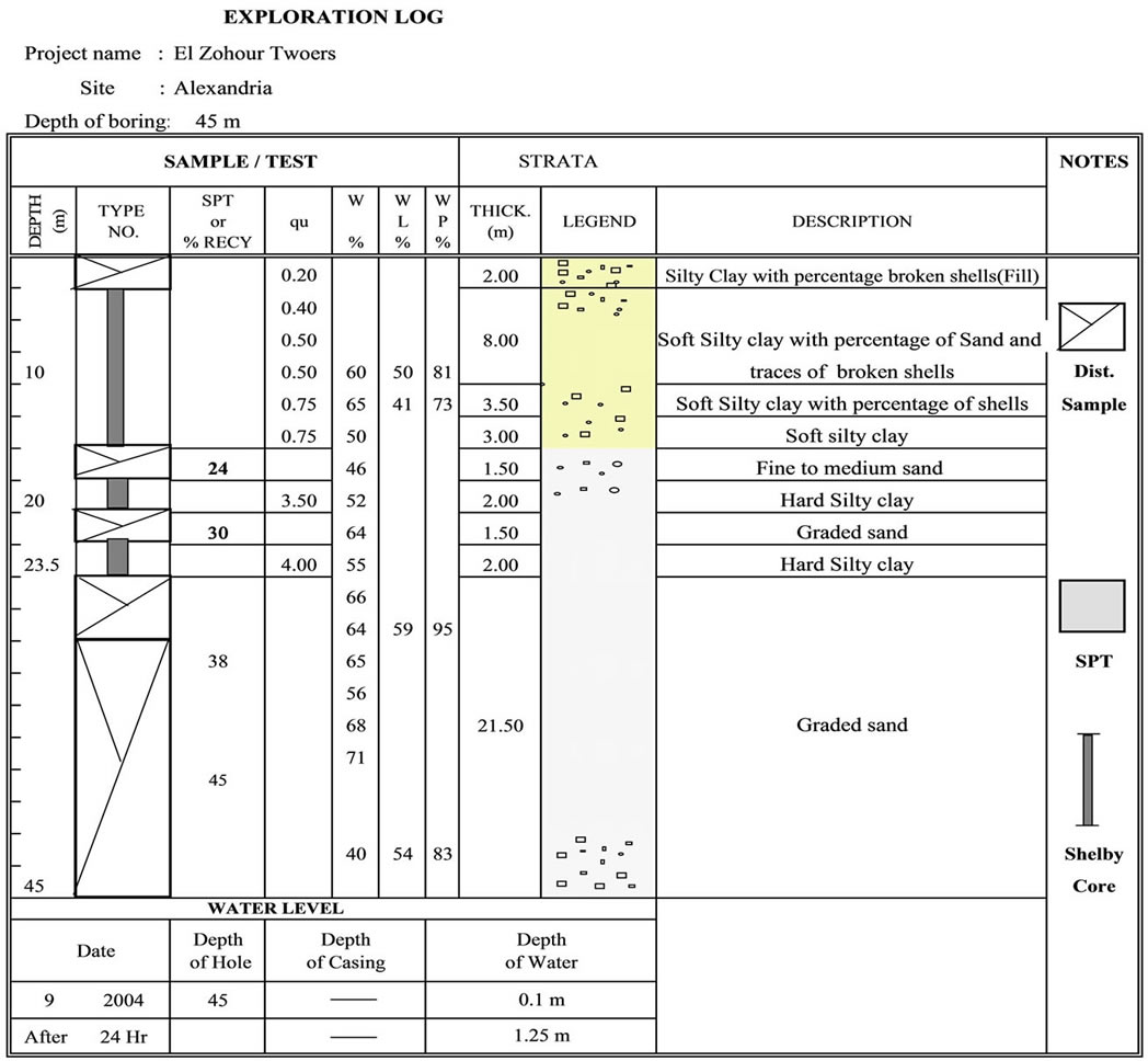
Figure 1. Soil profile of the investigated site.
3. Theoretical Prediction of Pile Load Capacity
A study of piles is quit complex and the estimation of carrying capacity is calculated from theoretical formula and load test results. Before execution of piles, estimation of pile load capacity is done by theoretical formula as follows:
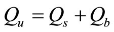 (1)
(1)
where:
 = ultimate pile capacity;
 = ultimate shaft resistance = surface area of shaft in contact with the soil
  shear strength of the soil;
 = ultimate base resistance;
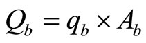 (1.2)
(1.2)
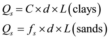 (1.3)
(1.3)
 = skin friction;
 = diameter of pile;
 = length of pile in contact with the soil;
 = adhesion;
 = base bearing capacity;
 = area of base.
Figure 2 shows the vertical loads (shaft resistance and base resistance) of pile.
The design resistance may be calculated using conventional static pile design theory. The theoretical pile capacities have been calculated by using Egyptian code (2005). The following Equations (2) and (3) are used to calculate the ultimate pile capacity of end bearing pile [7]. (Pile diameter used = 600 mm and Pile length = 27 m).
 (2)
(2)
where:
 = the working pile load at
 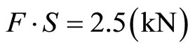 for end bearing and
  for shaft friction;
 = the average value of number of blows in (S.P.T) test for the effective soil at end bearing from distance (2R) blow base of pile;
 = the average number of blows in (S.P.T) test
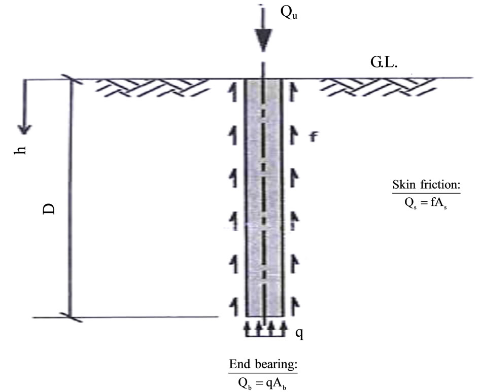
Figure 2. Vertical loads (shaft resistance and base resistance) of pile.
along of the pile length inside the layers of cohessionless soil;
 = radius of pile (meter) = 0.30 m;
 = length of penetration pile layers of cohessionless soil (meter)) = 7.50 m;
At investigated site the ultimate capacity of pile by using Equation (2) is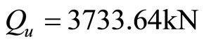 .
.
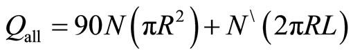
However, Egyptian code (2005) state that the ultimate capacity of pile can be estimated as follows:
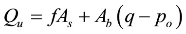 (3)
(3)
where:
 = ultimate capacity of pile;
 = side area of pile length;
 = base bearing area;
 = average stress (friction or adhesion);
 = average pressure stress on cross section of pile at base of pile;
 own weight of pile.
Table 1 shows the calculated theoretical ultimate pile capacity for pile diameter 60 cm with length 27.0 m. From this table it can be shown that the obtained Qult = 2250.08 Kn/m2 and after taken factor of safety (F·S = 2.0) then the . However, the allowable bearing capacity of pile for the investigated site is taken 1000 = kN/m2. Figure 3 shows the calculated ultimate capacity of the pile using Equations (2) and (3).
However, it can be shown from Equation (3) and Figure 3 that the percentage of friction load carried by the shaft along the pile length is about 46% of total load, while the pile load carried by the end bearing is 54% of total load.
4. Construction Method of Piles by Continuous Flight Auger (CFA)
The drilling process for (CFA) is suitable for penetrating dense layers and is unaffected by ground water or collapsing soil conditions. However, CFA method can be summarized as follows:
1) The pile is formed by first drilling into the ground with a continuous flight auger to the required depth;
2) Concrete is then injected under pressure through the auger’s hollow stem as it is being withdrawn;
3) The concrete pressure is maintained during the auger withdrawal so that it assists the extraction as well as exerting a lateral pressure on the surrounding soils;
4) Reinforcing cage is placed into the concrete column. Figure 4 shows the steps of execution process by con-
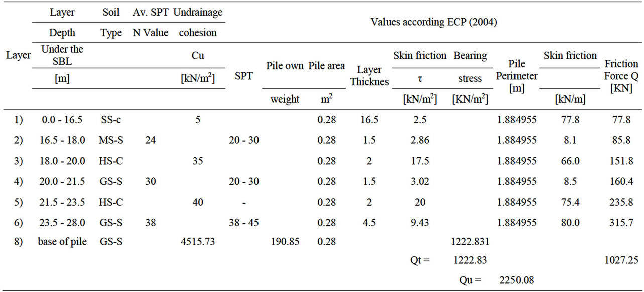
Table 1. The calculated theoretical ultimate pile capacity for pile diameter 60cm with length 27.0 m.
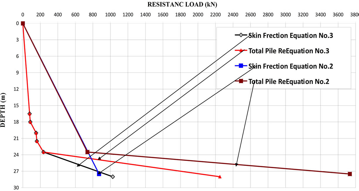
Figure 3. The relationship between the calculated theoretical capacity and depth of pile.
tinuous flight auger (CFA) piles. Figures 5-8 show the execution process by continuous flight auger (CFA) piles at the site.
5. Pile Load Tests
Load tests are performed to proof the design load and to check the pre-chosen factor of safety. In this study four pile load tests were performed on 600 mm diameter and 27 m lengths. The tests were done according to Egyptian Code. The test pile cap is shown in Figure 9. The reaction load was performed by a system of jacking bearing against dead load resting on a platform (Kentledge). The dead load was supplied by plastic sand bags on the platform as shown in Figure 10. The platform was supported on three wide flanged girder beams (reaction beams) placed side by side (and bolted together) over the jack. A hydraulic jack system comprising a 550 tons jack, pressure gauge, oil reservoir, pump and piping was used in the test. Settlement of the pile was recorded by means of four settlement dial gauges capable of reading to 0.01 mm precision. The gauges were mounted on two reference I-beams. The reference beam supports were at a clear distance > 2.5 m from the test pile head. All test piles were loaded in one cycle. Each increment (25% of the design load) was maintained for a maximum period of two hours or when settlement rate was observed to be less than 0.25 mm per hour. The loading test reaches a maximum load of one and half times the design load. Table 2 shows load increment in the test. Figure 11 shows the load settlement relationships for the four pile load tests.
6. Excavation of Site and Dewatering System
The site was excavated to the foundation level. The dewatering system was done in the site by surface dewa-
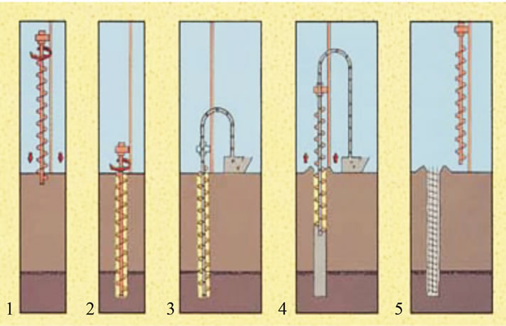
Figure 4. The steps of continuous flight auger (CFA) piles.
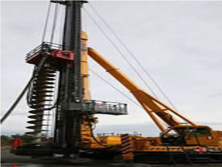
Figure 5. The machine used in execution of (CFA) piles.
tering. Figures 12-14 show the steps of excavation process of site and the dewatering system.
7. Ultimate Capacity of Piles Using Field Load Test Results
The ultimate capacities of the tested piles were deter-
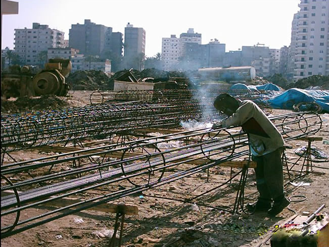
Figure 6. Fabrication of steel cage at site.
Figure 7. Drilling and concreting of pile by (CFA).
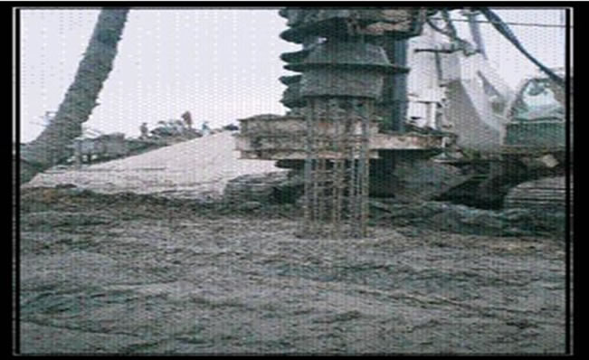
Figure 8. Reinforced steel cage inserted in concrete column by vibration.
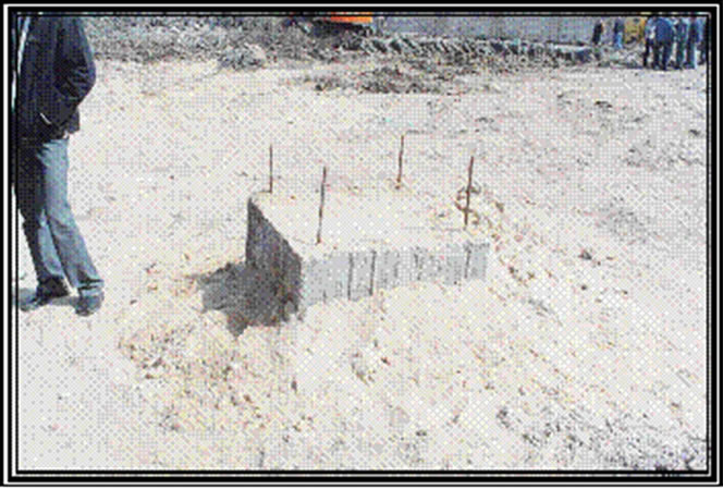
Figure 9. The pile cap of tested pile.
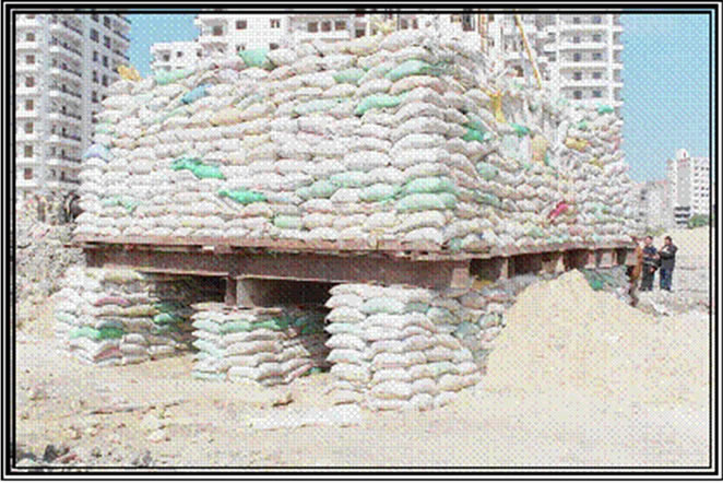
Figure 10. Knetledge method for pile test.
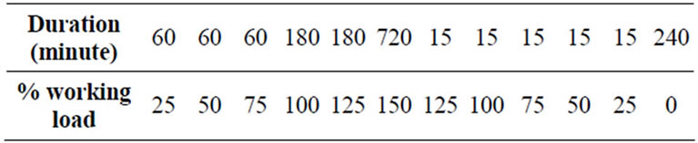
Table 2. loading-unloading procedure for pile test.
mined from the load test results using different approaches as follows.
7.1. Egyptian Code
Egyptian Code recommends that successful pile load test must confirm with the following Equation [7]:
 (4)
(4)
where:
S = settlement of pile;
S1 = settlement of pile at Qall;
S2 = settlement of pile at 1.25 Qall;
Qall = allowable load.
Table 3 shows the calculated allowable load capacity of pile load test using Equation (4) as .
.
7.2. Tangent-Tangent Method
Applying tangenttangent method as used Egyptian Code, a plot is made between stress and the settlement on semi logarithmic scale as shown in Figure 15 for pile load test #1 [7].
7.3. Hansen Method (1963)
Applying Hansen Method the square root of each settlement value from field load test data divided by the corresponding load value is plotted against the settlement as shown in Figure 16 for pile load test #2. Estimation of the ultimate load by Hansen Method is given by the formula [8]:
 (5)
(5)
where:
 = ultimate load capacity;
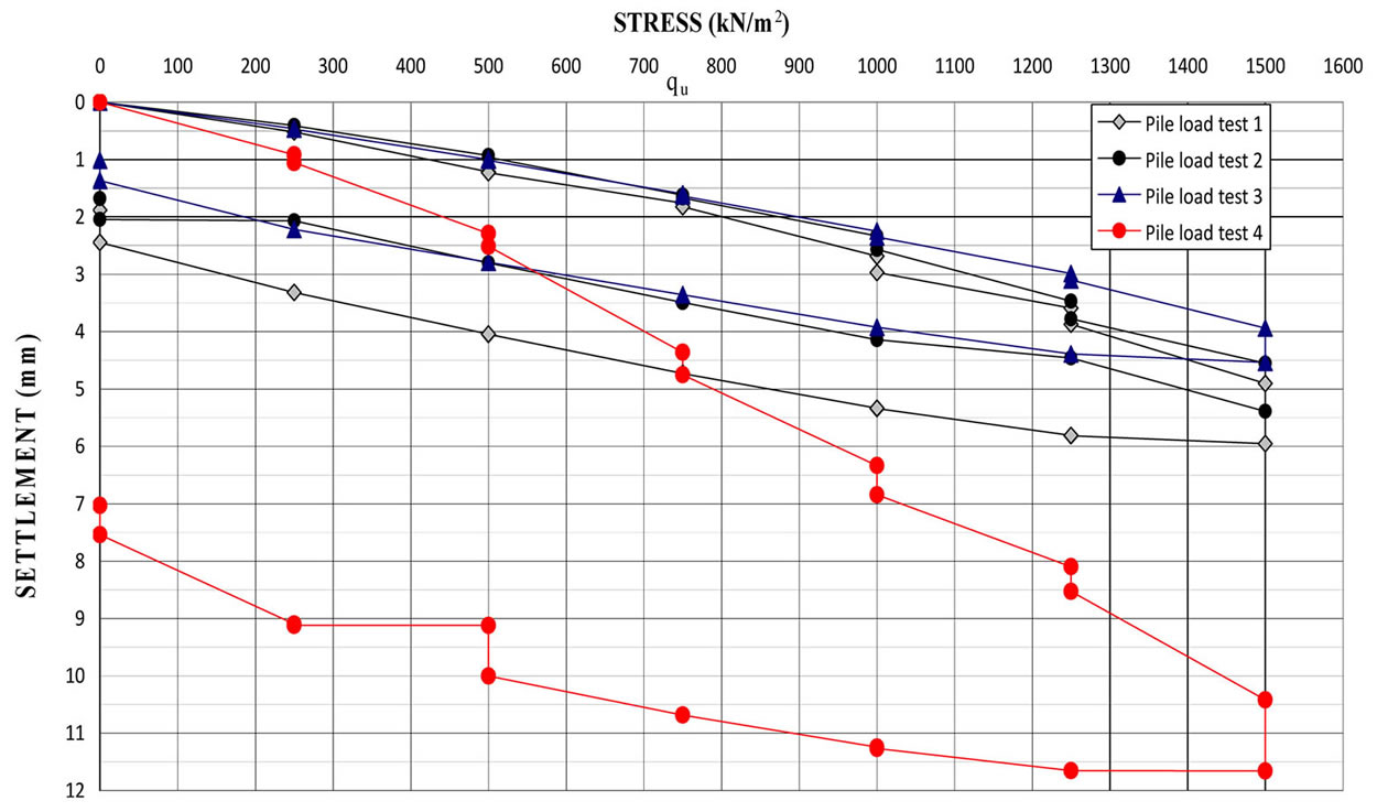
Figure 11. Load-settlement curve for piles load test.
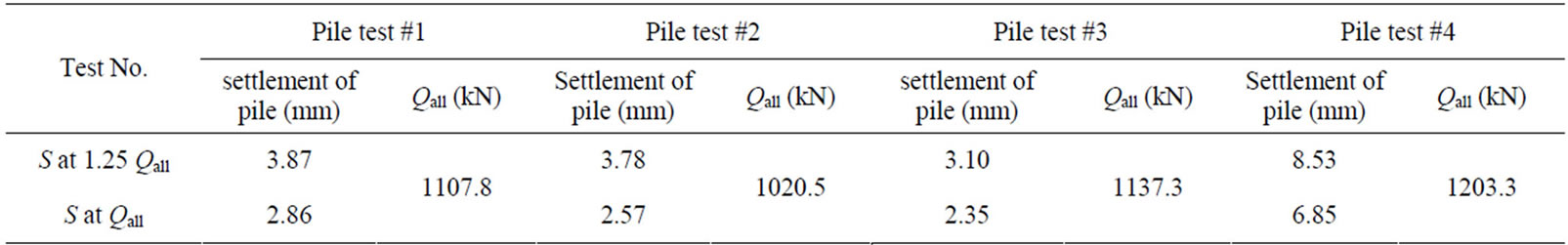
Table 3. Calculated allowable load capacity of pile for pile test.
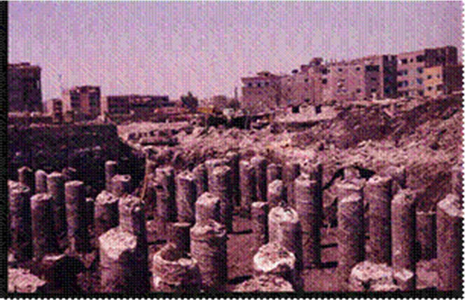
Figure 12. Site after excavation to requirement dept of raft foundation.
 = slope of the best fitting straight line.
 = y-intercept of the straight line.
7.4. Chin’s Method (1970)
Applying Chin’s method (Egyptian Code), a plot is made between settlement divided by corresponding load and the
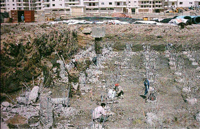
Figure 13. Remove of pile concrete head.
settlement as shown in Figure 17 for test pile #3. The inverse slope of the straight line gives the ultimate load as proposed by Chin [9].
7.5. Decourt’s Extrapolation (1999)
Applying Decourt’s Extrapolation by dividing each load by its corresponding settlement and plotting the resulting
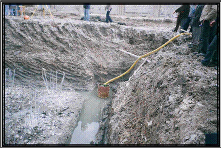
Figure 14. Surface dewatering of ground water for the site.
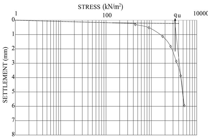
Figure 15. Ultimate pile capacities by tangent-tangent method for working pile load test #1.
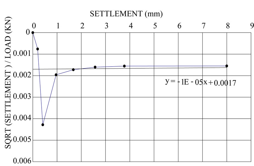
Figure 16. Ultimate pile capacity by Hansen Method for test pile #2.
values against the applied load. A linear regression over the apparent line (last three points) determines a line. Decourt identified the ultimate load as the intersection of this line with load axis as shown in Figure 18 for working test pile #4 [10].
8. Proposed Method for Determination of Ultimate Pile Capacity from Load Test
The measured settlement of pile is the sum of settlement due to friction and end bearing loads as well as the elastic deformation of the pile itself. The elastic deformation of
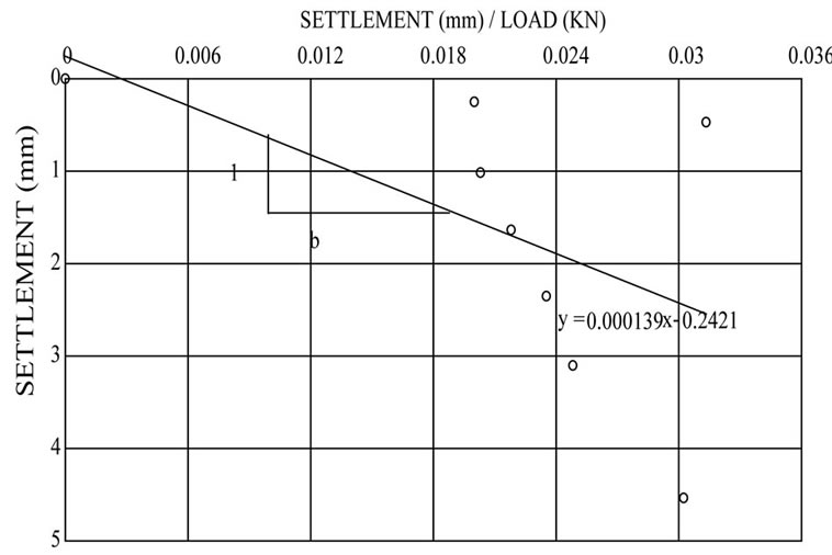
Figure 17. Ultimate pile capacity by Chin’s method for test pile #3.

Figure 18. Ultimate pile capacity using Decourt’s method for pile load test #4.
pile affects to a great extent the total settlement. However, the elastic deformation depends on the pile length itself and area of pile as well as the quality of concrete. Many authors and Codes such as NAVFAC and Egyptian Code recommended that the settlement at the top of a pile can be divided into three components [11,12].
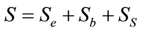 (6)
(6)
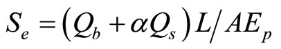 (7)
(7)
 (8)
(8)
 (9)
(9)
where:
Se = elastic deformation of pile;
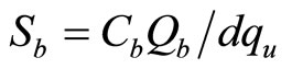
Sb = settlement of pile base due to the end bearing load;
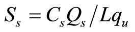
Ss = settlement of pile base due to the friction load;
Qb = end bearing load;
Qs = friction load;
qu = end bearing resistance;
L = pile depth;
A = area of cross section of pile;
d = pile diameter;
Ep = modulus of elasticity of pile;
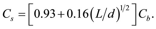
 ;
;
Cb = empirical factor depending on soil type and method of pile installation.
The proposed method depends on the settlement of pile without taken into consideration the elastic deformation. An empirical formula is presented from the relationship between stress and settlement of pile due to friction and end bearing only after deducting the elastic deformation of pile. However, the determination of ultimate load consists of the steps below:
1) Deducting elastic deformation of pile under each load increment from the measured settlement;
2) Plotting stress settlement curve from field load test data after deducting elastic deformation of pile (Figures 19-22);
3) The following proposed empirical formula has been obtained from the stress settlement mentioned relationships:
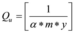 (10)
(10)
where:
Qu = ultimate load capacity (kN);
m = slope of the trend straight line;
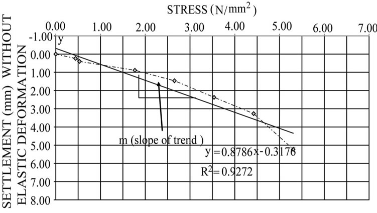
Figure 19. Ultimate pile capacity by using proposed method by the author for test pile #1 at Ep = 19677.40.
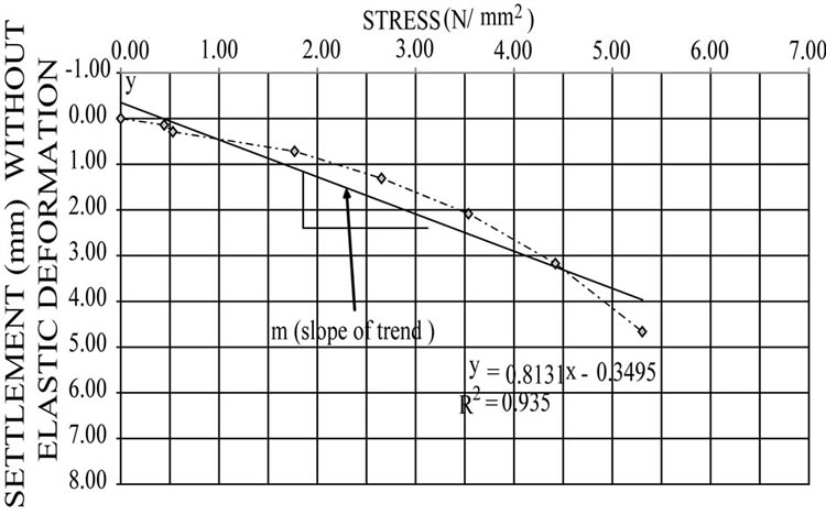
Figure 20. Ultimate pile capacity by using proposed method by the author for test pile #2 at Ep = 19677.40.
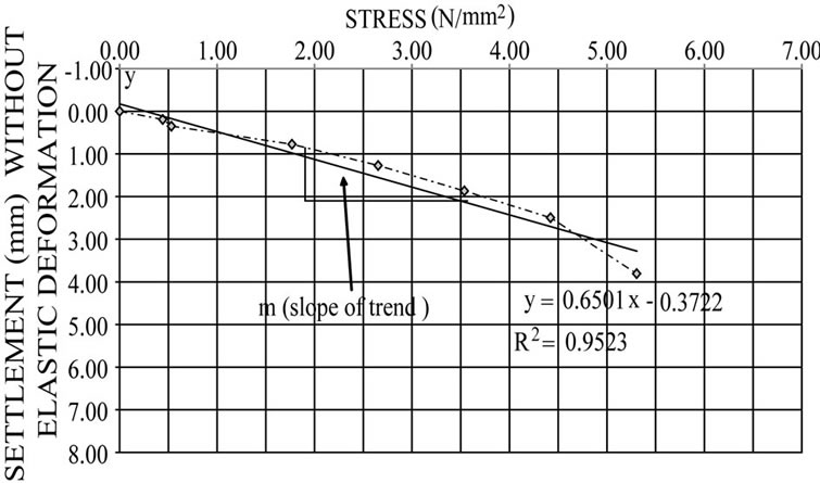
Figure 21. Ultimate pile capacity by using proposed method by the author for test pile #3 at Ep = 19677.40.
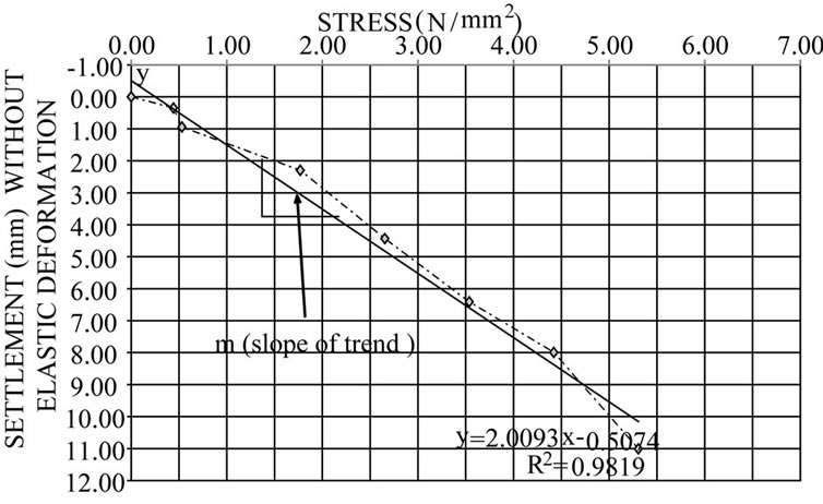
Figure 22. Ultimate pile capacity by using proposed method by the author for test pile #4 at Ep = 19677.40.
y = y-intercept of the straight line (as a value without sign);
α = factor depends on modulus of elasticity of concrete.
The values of the injected concrete elastic modulus  affect to a great extent the elastic deformation of piles. However, Table 4 shows the values of
  and the corresponding values of the coefficient
  that to be used in Equation (10).
The obtained results for the ultimate capacity of end bearing piles are considered to be more accurate than other methods. The proposed method appears to give bitter results that agree well with the theoretical predictions. However, Equation (3) is the most suitable and reliable method for predicting the theoretical capacity of piles before execution.
9. Comparison between Different Methods of Ultimate Pile Capacity Determination
The calculation of the ultimate capacity of piles and the corresponding factors of safety using the above mention methods are summarized in Table 5. The ultimate capacity obtained by various methods from the pile load test results are shown in Figure 23. However, pile load test #4
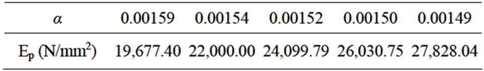
Table 4. loading-unloading procedure for pile test.
gives lower values due to excess settlement.
The new proposed method by the author for determining the ultimate capacity of end bearing piles appears to give a bitter result that agree well with the analytical predictions. However, Equation (3) is the most suitable and reliable method for predicting the theoretical capacity of piles before execution.
10. Load Carried by End Bearing and Friction along Shaft
The values of the ultimate pile capacity were taken from Table 5 and Figure 3 to evaluate the percentage of friction and end bearing capacity. Based on the above findings, it was found that the percentage of load carried by
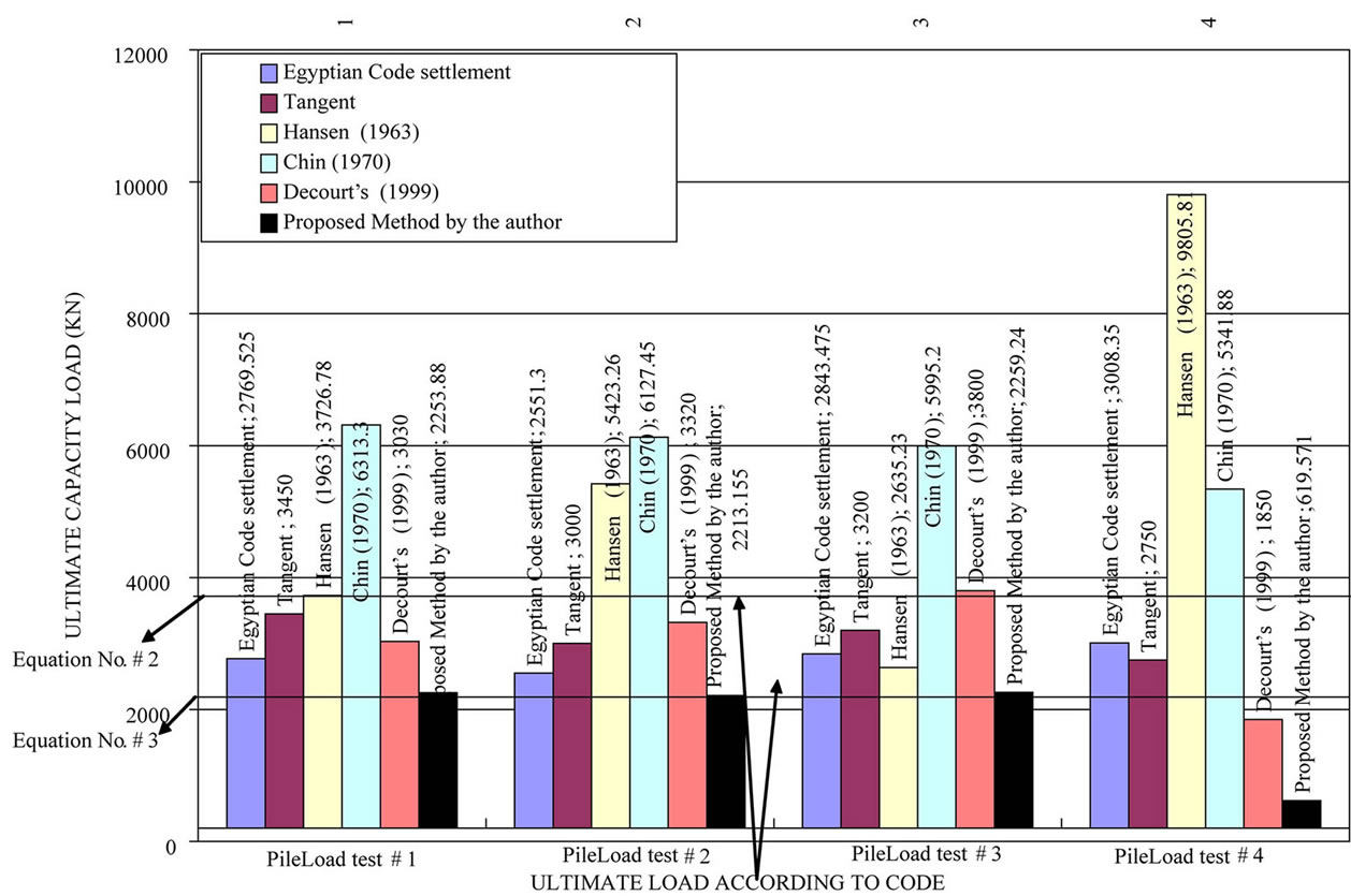
Figure 23. Comparison of ultimate pile loads using different methods.
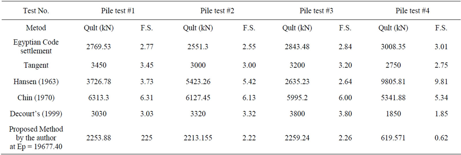
Table 5. Ultimate Capacity and factor of safety (F.S.) of Pile using different methods.
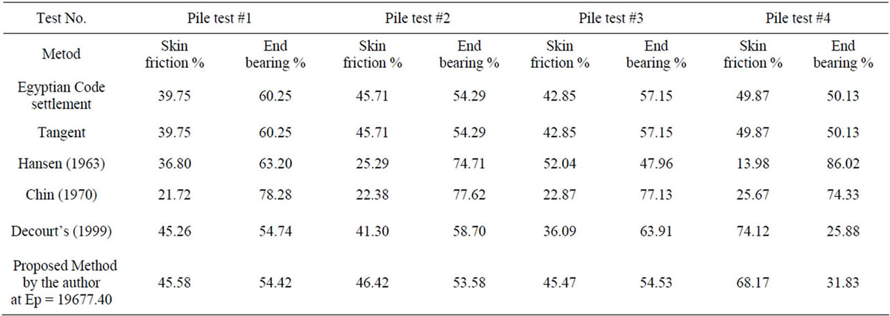
Table 6. Percentage of ultimate load carried by end bearing and friction.
friction along the pile shaft and the end bearing are shown in the Table 6. However, it can be shown that the proposed method gives the percentage of friction load carried by the shaft along the pile length to be about 46% of total load while the pile load carried by the end bearing is 54% of total load. In addition, the proposed method gives bitter results that agree with Equation (3).
11. Conclusions
From the test results the following conclusions are arrived:
1) A new proposed method to calculate the ultimate capacity of pile from pile load test is presented. The method is based on the relationship between the stress and settlement after deducting the elastic deformation of pile.
2) The proposed method for determining the ultimate capacity appears to give bitter results that agrees well with the theoretical predictions. The proposed method gives bitter results that agree with theoretical predictions.
3) The percentage of friction load carried by the shaft along the pile length is about 46% of total load, while the pile load carried by the end bearing is 54% of total load.
The proposed method is easier, quicker and more reliable.
12. Acknowledgements
The author would like to acknowledge the Fetih Construction Company for their valuable assistance.
REFERENCES
- T. Y. C. Ir, C. M. G. Chow and S. B. Partners, “Design & Construction of Bored Pile Foundation,” Geotechnical Course for Pile Foundation Design & Construction, Ipoh, 29-30 September 2003, pp. 1-74.
- A. B. Dan, D. D. Steven, W. T. Robert and A. L. Carlos “Design and Construction of Continuous Flight Auger (CFA) Piles,” Geotechnical Engineering Circular No. 8. April Office of Technology Application Office of Engineering/Bridge, Division Federal Highway Administration, US Department of Transportation, Washington DC, 2007, pp. 33-65.
- A. Akbar, S. Khilji, S. B. Khan, M. S. Qureshi and M. Sattar, “Shaft Friction of Bored Piles in Hard Clay,” Pakistan Journal of Engineering and Applied Science, Vol. 3, No. 3, 2008, pp. 54-60.
- K. Ishihara, “Recent Advances in Pile Testing and Diaphragm Wall Construction in Japan,” Geotechnical Engineering Journal of the SEAGS & AGSSEA, Vol. 41, No. 3, 2010, pp. 1-43.
- M. Suman and Y. Noriyuki, “End Bearing Capacity of Tapered Piles in Sands using Cavity Expansion Theory,” Memoirs of the Faculty of Engineering, Kyushu University, Vol. 71, No. 4, 2011, pp. 77-99.
- W. N. Elsamee, “Evaluation of the Ultimate Capacity of Friction Piles,” Engineering, Vol. 4 No. 11, 2012, pp. 778-789. doi:10.4236/eng.2012.411100
- Egyptian Code, “Soil Mechanics and Foundation,” Organization, Cairo, 2005.
- J. B. Hansen, “Discussion on Hyperbolic Stress-Strain Response, Cohesive Soils,” Journal for Soil Mechanics and Foundation Engineering, Vol. 89, 1963, pp. 241-242.
- F. K. Chin, “Estimation of the Ultimate Load of Piles from Tests Not Carried to Failure,” Proceedings of Second Southeast Asian Conference on Soil Engineering, Singapore, 11-15 June 1970, pp. 81-92.
- D. M. Dewaikar and M. J. Pallavi, “Analysis of Pile Load Tests Data” Journal of Southeast Asian Geotechnical Society, Vol. 89, No. 4, 2000, pp. 27-39.
- M. Das Braja, “Principle of Foundation Engineering,” 7th Edition, USA Cengage Brain.com, 2011.
- NAVFAC, DM-7.2, “Foundations and Earth Structures,” Design Manual, Department of the Navy Facilities Engineering Command, Alexandria, 1982.