Engineering
Vol.4 No.11(2012), Article ID:24525,4 pages DOI:10.4236/eng.2012.411094
Design, Modeling and Analysis of Implementing a Multilayer Piezoelectric Vibration Energy Harvesting Mechanism in the Vehicle Suspension
1Department of Mechanical Engineering, Faculty of Industrial Technology, Institut Teknologi Sepuluh Nopember, Surabaya, Indonesia
2Department of Mechanical Engineering, Faculty of Industrial Technology, Institut Teknologi Sepuluh Nopember, Surabaya, Indonesia
Email: wiwiek@me.its.ac.id
Received September 11, 2012; revised October 10, 2012; accepted October 20, 2012
Keywords: Vibration Energy Harvesting; Multilayer Piezoelectric; Force Amplifying Mechanism; Vehicle Suspension
ABSTRACT
This paper deals with the design, modeling and analysis of implementing a Multilayer Piezoelectric Vibration Energy Harvesting (ML PZT VEH) Mechanism in the vehicle suspension. The principle of work of the proposed ML PZT VEH mechanism is reducing the relative motion of the suspension, amplifying the applied force to the PZT by a specific design of mechanism and combining a single layer PZT into multilayer PZT to increase the produced electricity. To maintain the performance of suspension as the original suspension, the ML PZT VEH mechanism is mounted in series with the spring of the suspension. The proposed ML PZT VEH mechanism and its implementation to the vehicle suspension were mathematically modeled. Responses of the vehicle before and after implementing ML PZT VEH mechanism were simulated. The results show the proposed mechanism can produce output voltage of 2.75 and power of 7.17 times bigger than direct mounting to the vehicle suspension. And the simulation result shows that mounting ML PZT VEH mechanism in series with the spring of the vehicle suspension does not change the performance of suspension.
1. Introduction
Only 10% - 16% of the fuel energy is used to drive the car, to overcome the resistance from road friction and air drag. One important loss is the dissipation of vibration energy by shock absorber of the vehicle suspension due to road irregularity, vehicle acceleration and deceleration [1,2]. The research about energy recovery from vehicle suspensions began more than ten years ago as an auxiliary power source for active suspension, and also as energy regenerating devices.
Suda et al. [3,4] investigated a self powered active suspension control system, in which one motor is used to generate electricity and another motor is used to control the vibration. Nakano et al. [5] also investigated the self-power vibration control using a single motor, in which a variable resistor, a charging capacitor and relay switches were used to control the motor force to follow the desired skyhook damping force. Okada et al. [6,7] proposed an active-regenerative control for suspension, in which energy is regenerated at high speed motion, and active control is used to provide damping at low speed when the regenerative voltage lower than the battery voltage.
Gysen et al. [8] designed an electromagnetic regenerative suspension by modifying the shock absorber using permanent magnet and coil. Gupta et al. [9] and Zuo et al. [10] implemented an electromagnetic regenerative suspension in the vehicle suspension and investigated the performance experimentally. They used 1:2 prototype of regenerative suspension and could regenerate power of 16 - 64 W at RMS speed of 0.25 - 0.5 m/s. Rajamani and Hedrick [11] developed a hydraulic-regenerative shock absorber by combining a hydraulic system and rotary electromagnetic generator. The effect of fluid viscousity to the transmission of hydraulic power was done by Avadhany [12]. The industry has also attemted to bring active suspensions into practice by making use of some of the vibration energy and reducing the power consumption. For example, Levant Power Corporation [13] has fabricated a regenerative rotary shock absorber named GENSHOCK and tested the GENSHOCK by implementing it in the Humvee suspension running on the standard road. It can regenerate power of 500 W. Another example is one feature in Bose’s active suspension [14] equipped by a regenerative power amplifiers which allow power to be returned from the motor.
Pickelman et al. [15] developed a regenerative shock absorber using piezoelectric material mounted on the top of the shock absorber cylinder. Arizti [16] investigated the use of multilayer piezoelectric for regenerative shock absorber. Response of the regenerative shock absorber with multilayer piezoelectric due to bump and harmonic excitations were mathematically modeled and simulated. The regenerated electricity is 17.69 mV, smaller than typical electromagnetic regenerative shock absorbers. However, the use of piezoelectric has some advantages, such as its compatibility and size.
To increase the generated electricity from piezoelectric material, multilayer or piezoelectric stack is usually used. However, the epoxy interlayer bonds in multilayer piezoelectric transducer has a significant effect on the electromechanical properties. This phenomena has been reported by Saillant et al. [17]. To obtain optimum performance, the thickness of the interlayer bond should be minimized. Luo et al. reported the use of piezoelectric stack in a vibration energy harvesting mechanism which can produce electricity in two direction of excitation [18]. Lie et al. developed in a different design of mechanism using piezoelectric stack to harvest the vibration energy of a vibrating machine [19]. Feenstra et al. developed a mechanically amplified piezoelectric stack to harvest the vibration energy through a backpack that can generate electrical energy from the differential forces between the wearer and the pack [20].
All research about energy recovery from vehicle suspensions are done by modifying the shock absorber using electromagnetic or piezoelectric material to regenerate energy. This paper aims at designing, modeling and analyzing the implementation of a Multilayer Piezoelectric Vibration Energy Harvesting (ML PZT VEH) Mechanism in the vehicle suspension. The principle of work of the proposed ML PZT VEH mechanism is amplifying the applied force to the PZT by a specific design of the mechanism and combining a single layer PZT into multilayer PZT to increase the produced electricity. To maintain the performance of the suspension as the original suspension, the ML PZT VEH mechanism is mounted in series with the spring of the suspension. The proposed ML PZT VEH mechanism and its implementation to the vehicle suspension were mathematically modeled and simulated. This paper is organized as follows. In Section 2 we outline the design concept of the ML PZT mechanism. In Section 3 we mathematically model the dynamics of vehicle with and without the ML PZT mechanism. In Section 4 we describe and discuss the results. Conclusions are then presented in Section 5.
2. The ML PZT VEH Mechanism
The ML PZT VEH mechanism is used to harvest the vibration energy from the vehicle suspension and is designed to be mounted in series with the spring of the suspension. Vibration from spring of the suspension will be transfered to the ML PZT VEH mechanism and converted into electricity. Figure 1 shows the proposed ML PZT VEH mechanism. The ML PZT VEH mechanism is designed to reduce the relative displacement of the suspension and to increase or amplify the spring force of the suspension. The principle of work of the mechanism is detailed as follows. Relative vertical displacement of the suspension will be converted and reduced into horizontal displacement by the mechanism, and then transfered to the ML PZT. The spring force of the suspension is amplified and transfered to the ML PZT. The ML PZT will convert the amplified spring force into electricity. As shown in Figure 3, elastic rubber is placed at the outer part of the ML PZT to compensate excessive force from the suspension and maintain the ML PZT safe.
As shown in the Figure 1, spring force from the suspension is transfered to the body 1 (L1) of the mechanism, called .
.  will produce oscilating vertical motion y (t) of body 1 (L1). The oscilating vertical motion y (t) of body 1 (L1) will produce oscilating angular motion
  of body 2 (L2), horizontal motion x (t) of body 3 (L3) and oscilating horizontal deflection of the ML PZT.
The kinematics relationship of the ML PZT VEH mechanism is described in Figure 2. Angular displacement from  to
to  will produce linear displacement from A1 to A2 and from B1 to B2. And its relationship can be written as follows.
 (1)
(1)
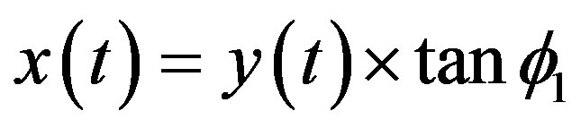
Equation (1) shows that ratio of the horizontal displacement to the vertical displacement of the mechanism depends on the initial angle of the ML PZT VEH mechanism . Therefore, the kinematical relation between vertical and horizontal force; and vertical and horizontal displacement of the ML PZT VEH mechanism can be expressed as follows Equations (2) and (3).
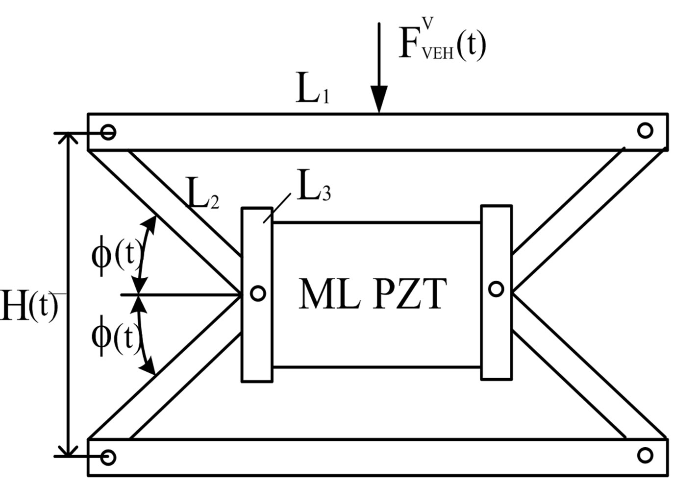
Figure 1. Schematic diagram of ML PZT VEH mechanism.
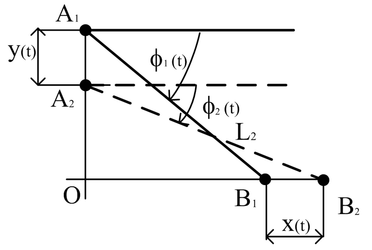
Figure 2. Kinematic of mechanism showing the relation between ,
,  and
and .
.
 (2)
(2)
 (3)
(3)
The structure of ML PZT and rubber in the ML PZT VEH mechanism is shown in Figure 3. Elastic rubber is placed on the outer part of the ML PZT to compensate excessive force, preload from the suspension and to keep the ML PZT not damaged. When the ML PZT VEH mechanism subjected to harmonic force, the ML PZT will experience amplified harmonic force and generate electrical energy.
As the damping effect of the ML PZT is small and negligible, the equilibrium of force of the ML PZT can be written as:
 (4)
(4)
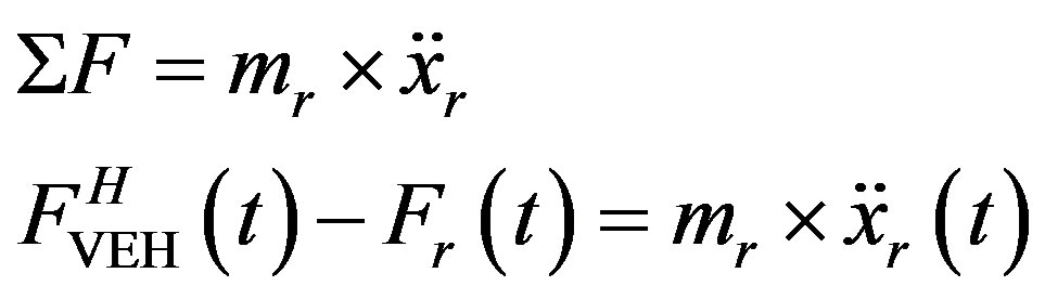
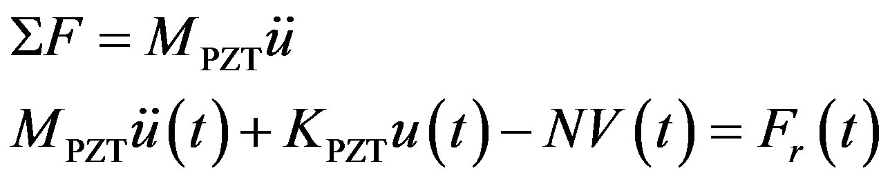
Based on the Newton second law of motion, the equilibrium of dynamic forces of the ML PZT mechanism is written as follows.
 (5)
(5)
As the rubber mass is small and negligible, Equation (5) can be written as:
 (6)
(6)
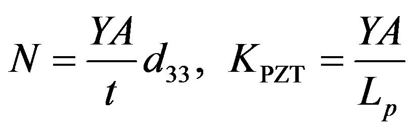
The ML PZT consists of several layer of piezoelectric element as shown in Figure 4, where each element has exactly the same mechanical and electrical responses. The equation of force equilibrium of the system can be written as:
 (7)
(7)
For multilayer piezoelectric (stack) Equation (7) can be written as:
 (8)
(8)

Figure 3. The structure of ML PZT with elastic mass (rubber).
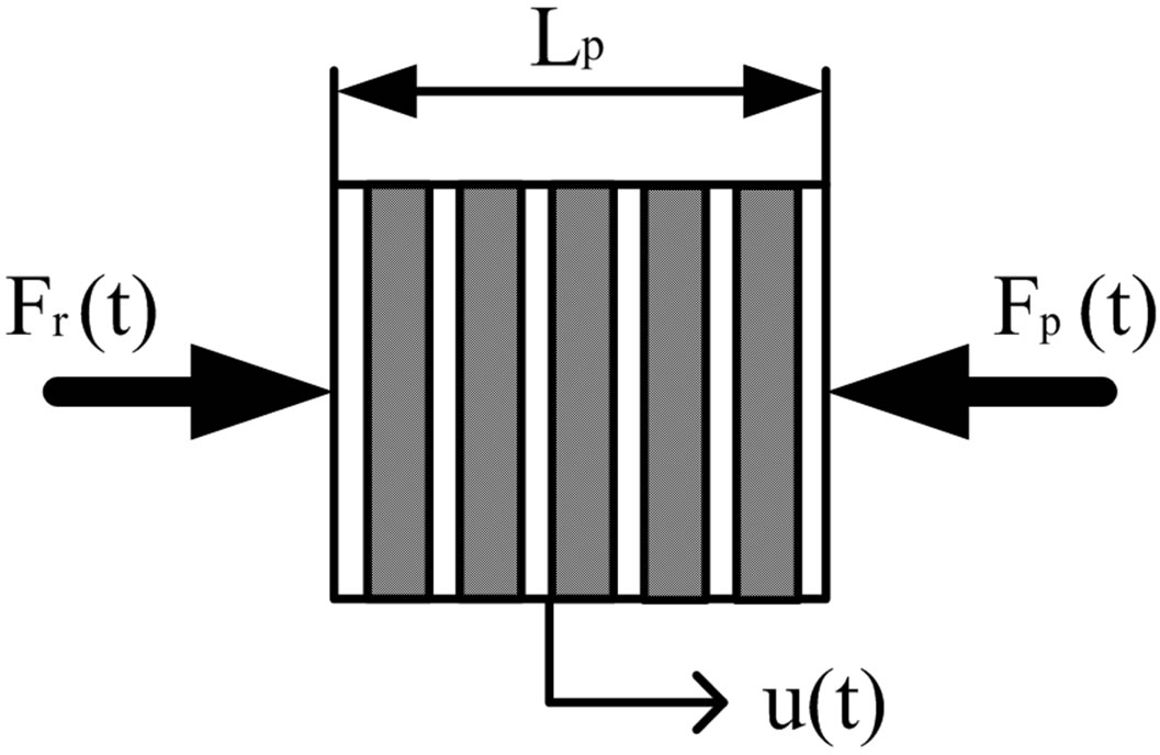
Figure 4. Force equilibrium of ML PZT.
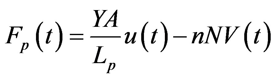
Using constitutive equation for piezoelectric material, the ML PZT can be mathematically modeled as a single degree of freedom. The equilibrium of force of the system between mechanical and electrical component is shown in Figure 5. The equation of mechanical and electrical coupling can be derived as follows.
 (9)
(9)
where,
3. Vehicle Dynamic Analysis
3.1. Without ML PZT VEH Mechanism
Figure 6(a) illustrates a quarter car model of vehicle with two degree of freedom (2DOF). Excitation from road profile is represented by y(t). Figure 6(b) shows the free body diagram of sprung mass and unsprung mass of the quarter car model. Based on the Newton’s second law of motion, the follwing equations can be derived from the free body diagrams.
3.1.1. Free Body Diagram of the Unsprung Mass
 (10)
(10)
Laplace transformation of Equation (10) is:
 (11)
(11)

Figure 5. Free body diagram of mechanical-electrical system of the PZT.

Figure 6. (a) A quarter car model of vehicle with two degree of freedom; (b) Free body diagram of sprung and unsprung mass.
And the displacement of unsprung mass can be written as
 (12)
(12)
where,

3.1.2. Free Body Diagram of the Sprung Mass
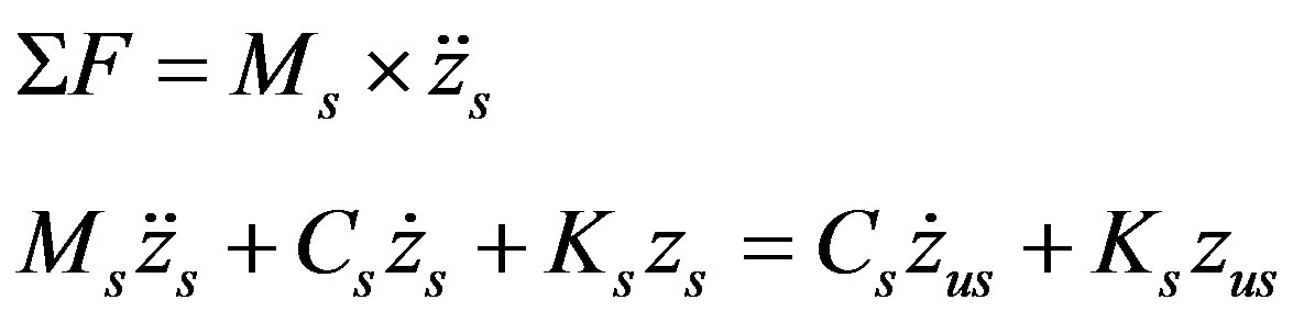 (13)
(13)
Laplace transformation of Equation (13) is:
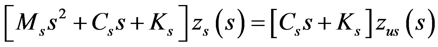 (14)
(14)
And the displacement of sprung mass can be written as
 (15)
(15)
where,

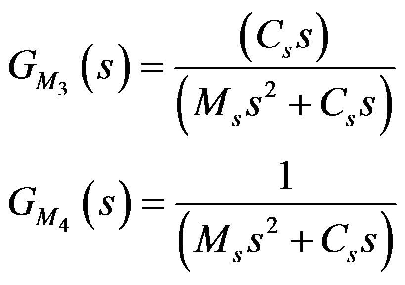
Based on Equations (12) and (15), the transfer function of the vehicle dynamic without ML PZT VEH mechanism showing the relation between excitation and displacement of the sprung mass can be represented in the block diagram as shown in Figure 7.
3.2. With ML PZT VEH Mechanism
In this paper, the proposed method to regenerate vibration energy from vehicle suspension is by implementing the ML PZT VEH mechanism without changing the performance of the suspension. The principle of work of the ML PZT VEH mechanism is amplifying the applied force to the PZT by a specific design of the mechanism and combining a single layer PZT into multilayer PZT to increase the produced electricity. To maintain the performance of the suspension as the original suspension, the ML PZT VEH mechanism is mounted in series with the spring of the suspension.
Figure 8 shows a quarter car model of vehicle with ML PZT VEH mechanism mounted in series with the spring of the suspension in two degree of freedom (2DOF). Excitation from road profile is represented by y (t). Figure 9 shows the free body diagram of sprung mass and unsprung mass of the quarter car model. Based on the Newton’s second law of motion, the following equations can be derived from the free body diagrams.
3.2.1. Free Body Diagram of the Unsprung Mass
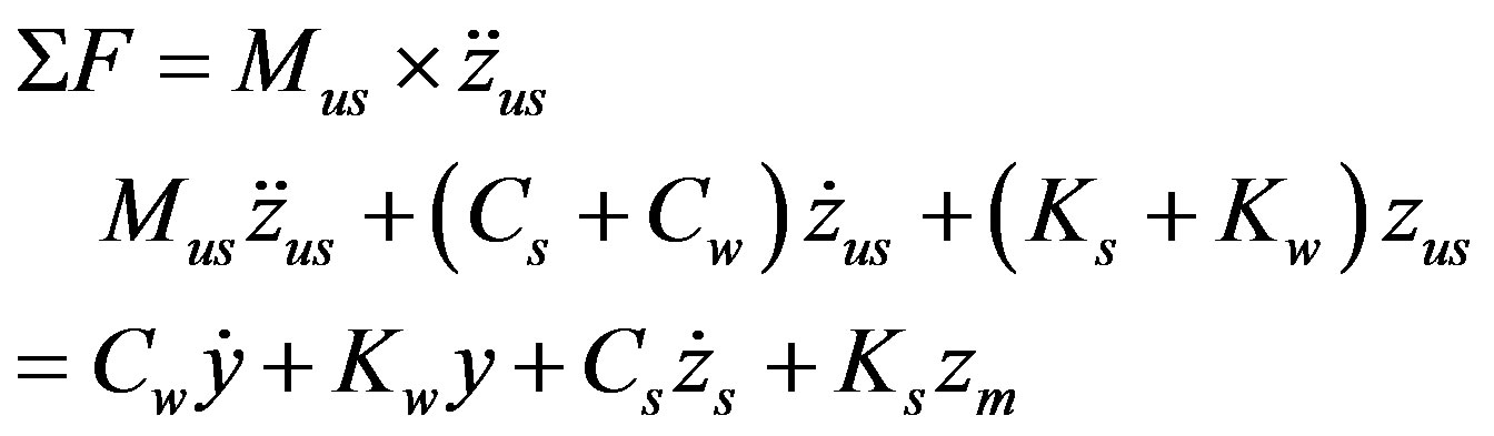 (16)
(16)
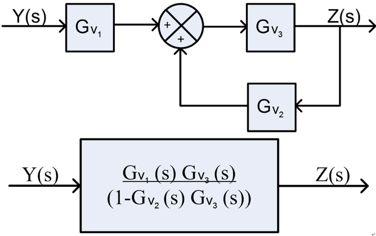
Figure 7. Block diagram of the vehicle without ML PZT VEH mechanism.
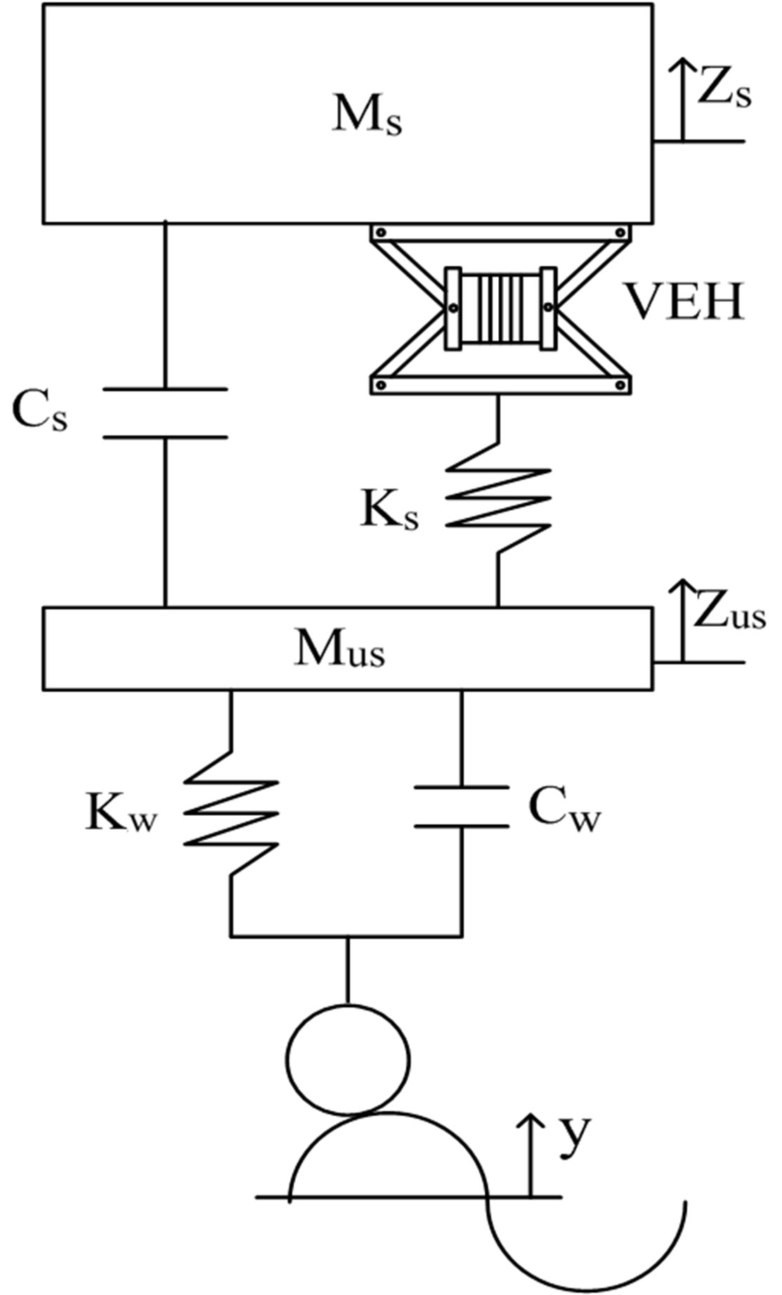
Figure 8. The structure of vehicle, suspension and ML PZT VEH mechanism.

Figure 9. Free body diagram of the vehicle and ML PZT VEH mechanism.
Laplace transformation of Equation (16) is:
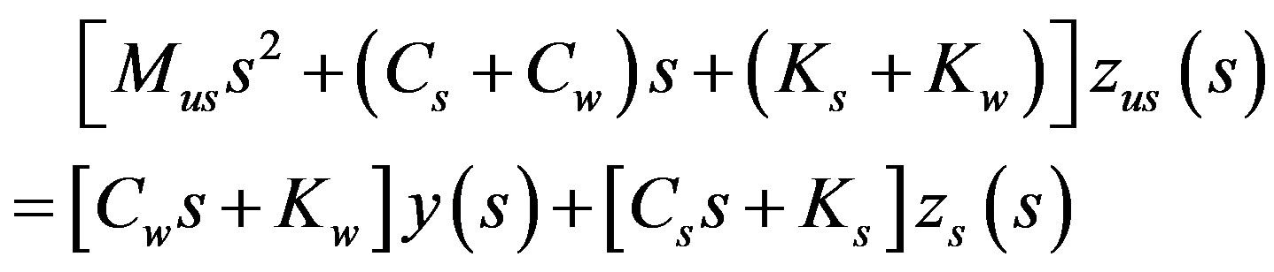 (17)
(17)
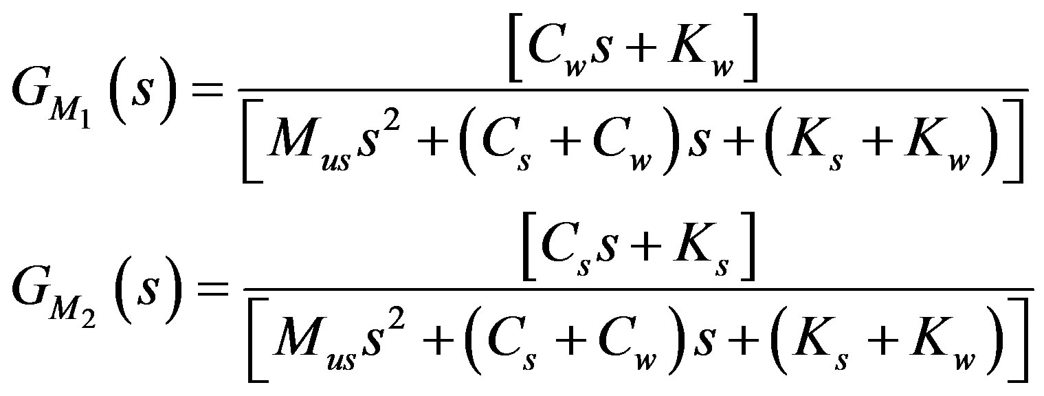
And the displacement of unsprung mass can be written as
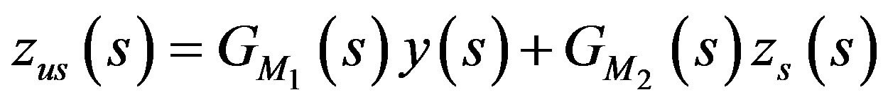 (18)
(18)
where,
3.2.2. Free Body Diagram of the Sprung Mass
 (19)
(19)
Laplace transformation of Equation (19) is:
 (20)
(20)
And the displacement of unsprung mass can be written as
 (21)
(21)
where,
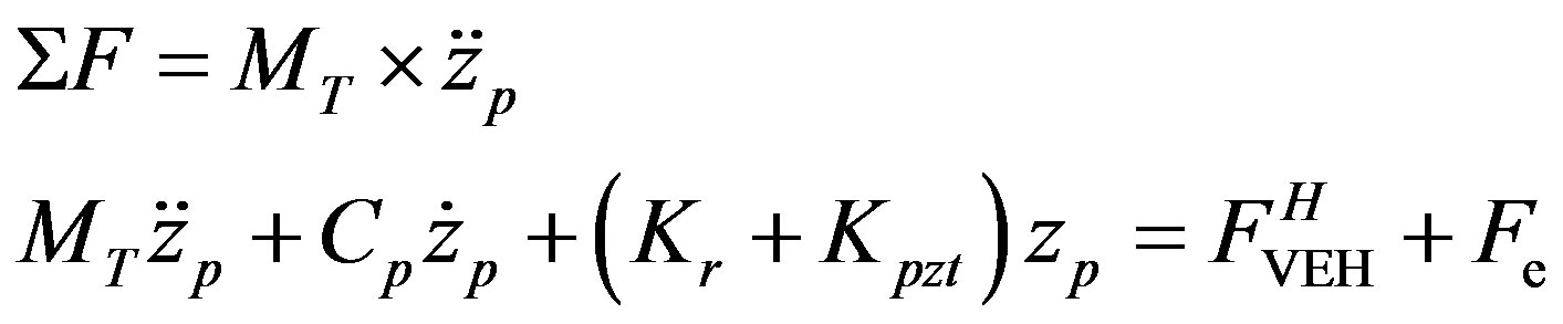
3.2.3. Free Body Diagram of the ML PZT VEH Mechanism
 (22)
(22)
As the deflection of the mechanism is extremely small compared to the displacement of Ms, and the ML PZT VEH mechanism is attached firmly at the sprung mass (the body of vehicle), the displacement, velocity and acceleration of the ML PZT VEH mechanism is the same to those of the sprung ( and
and ). Therefore, Equation (22) can be written as:
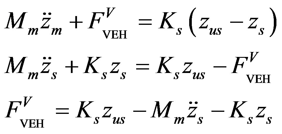 (23)
(23)
From Equation (23), it can be seen that the ML PZT VEH mechanism is subjected to a force known as . By Laplace transformation, Equation (23) is written as:
 (24)
(24)
where,
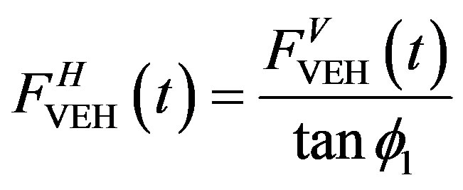
Figures 10 and 11 illustrate the ML PZT VEH mechanism and the free body diagram of its mechanical and electrical system. Due to the geometrical design of the mechanism, the vertical applied force  is transformed into horizontal force
 , and then the horizontal force
  will push the pusher rod/mass Mp
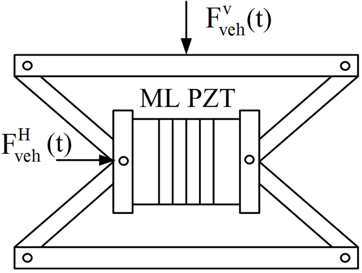
Figure 10. ML PZT VEH mechanism.

Figure 11. Free body diagram of mechanical-electrical system of the ML PZT VEH mechanism.
and the ML PZT. Assuming that the friction of the mechanism is small enough, the vertical applied force  is transformed into horizontal force
  directly without delay. Therefore, there is no phase leg between the vertical applied force
  and the horizontal force
 .
.
Based on the model and its free body diagram illustrated in Figures 10 and 11, the following mathematical equations expressing the dynamics of the mechanical and electrical systems are obtained.
3.2.4. Free Body Diagram of the Pusher Mass of the ML PZT VEH Mechanism
 (25)
(25)
where,

Laplace transformation of Equation (25) is:
 (26)
(26)
And the displacement of the pusher mass can be written as
 (27)
(27)
where,
3.2.5. Mathematical Model of the Electrical System of the ML PZT
 (28)
(28)
where,
 (29)
(29)
Laplace transformation of Equation (29) is:
 (30)
(30)
where,

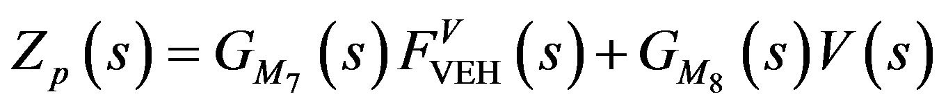
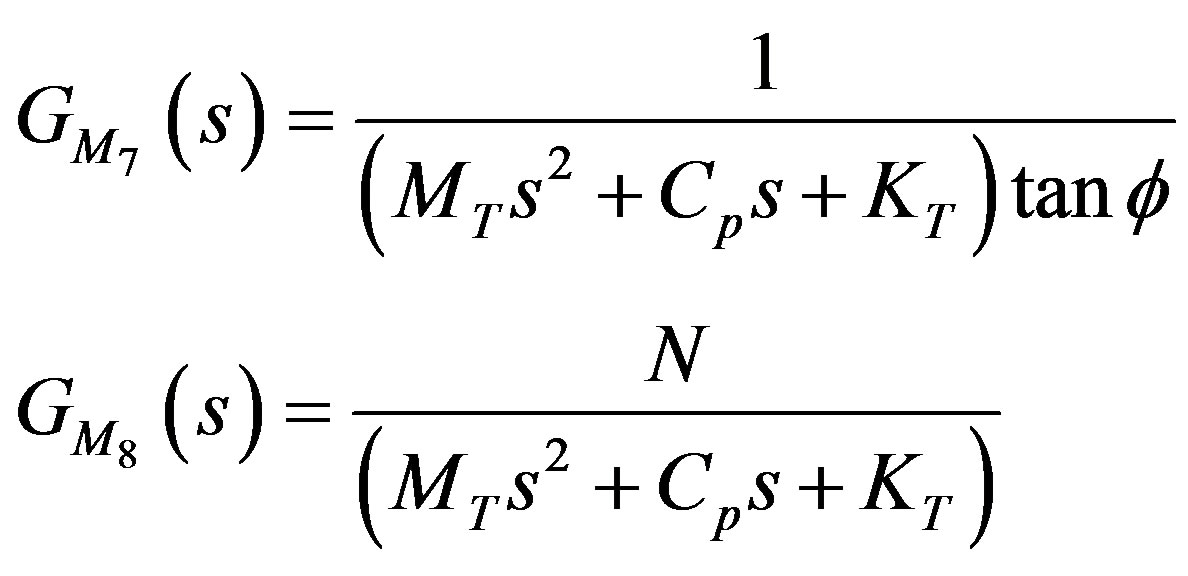
Assuming that the load impedance will be the same as the source, thus the impedance of electrical system is defined as follows:
 (31)
(31)
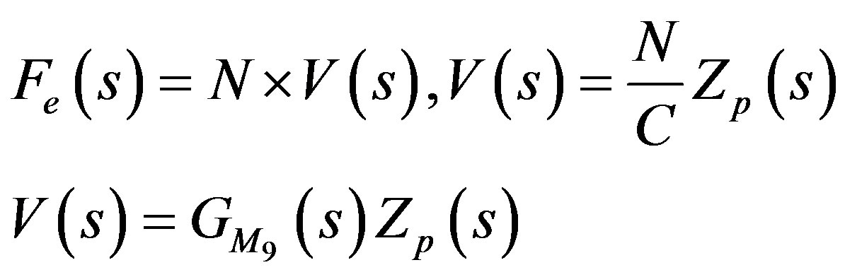
Using the defined impedance of Equation (31), the output power of the system can then be defined as:
 (32)
(32)
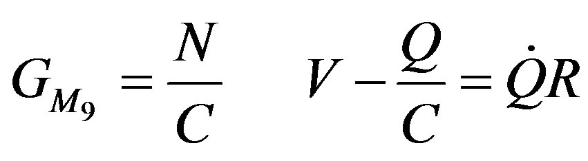
where,
 (33)
(33)
And the Laplace Transform of Equation (33) is:
 (34)
(34)
And the output power of Equation (32) can then be written as:
 (35)
(35)
where,

where,
With the equations defined above, the electrical response of the ML PZT (stack) can be found when subjected to a known dynamic force. And the block diagram showing the transfer function of the mechanical and electrical system is shown in Figure 12. And Table 1 shows the parameters used in the simulation.
4. Result and Discussion
4.1. Response of the Vehicle
This part highlights the result of simulation showing the response of vehicle without and with ML PZT VEH mechanism in the time and frequency domain. Figures 13-15 show the displacement, velocity and acceleration responses of the vehicle without and with ML PZT VEH mechanism subjected to step input/excitation in the time domain (transient response of the vehicle system). The initial value and magnitude of the step input used in the simulation are 0.5 s and 0.1 m respectively. In the figures, the displacement-velocity-acceleration of sprung and unsprung of the vehicle without ML PZT VEH mechanism (Zs; Zus; Zs (dot); Zus (dot); Zs (dot-dot); Zus (dotdot)) and the displacement-velocity-acceleration of sprung and unsprung of the vehicle with ML PZT VEH mechanism ( ;
; ;
; (dot);
  (dot);
  (dotdot);
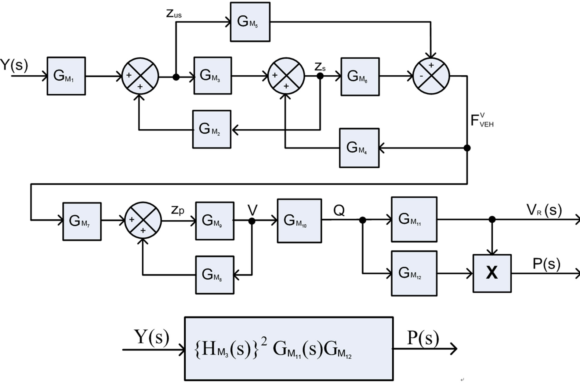
Figure 12. Block diagram of the vehicle with ML PZT VEH mechanism.
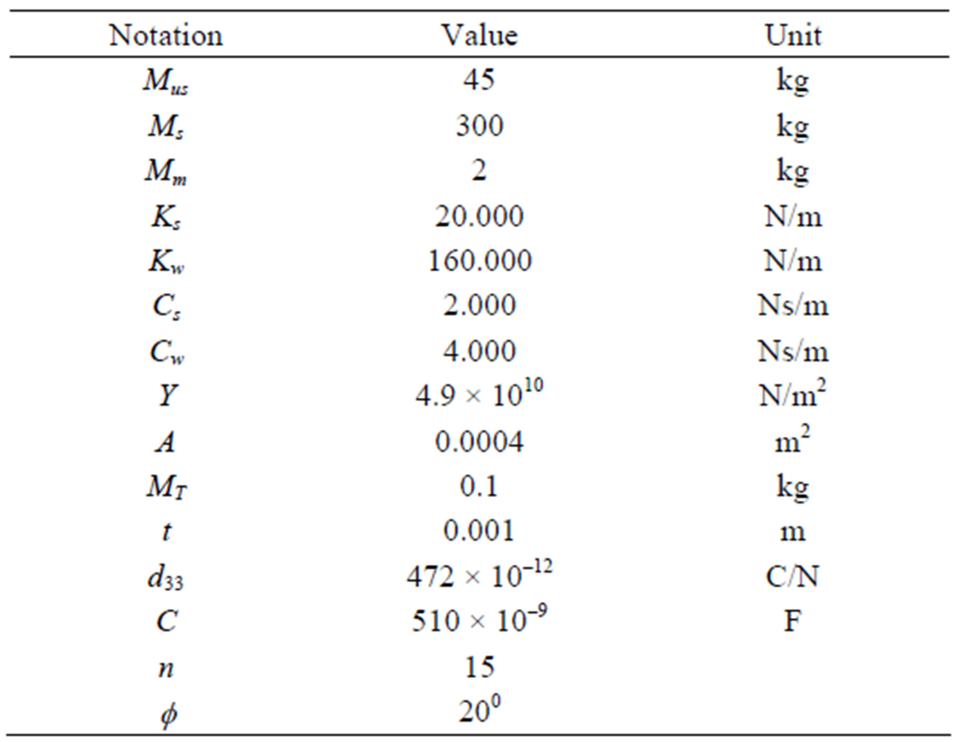
Table 1. Parameters used in the simulation.
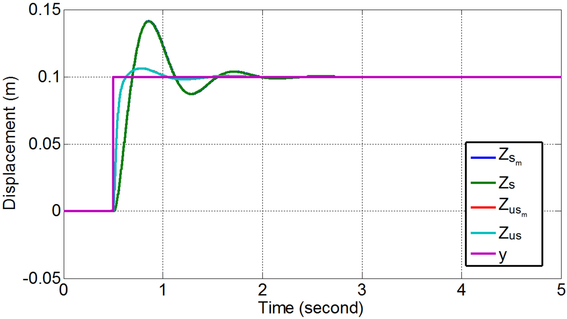
Figure 13. Displacement responses of the vehicle’s sprung and unsprung mass subjected to step input.
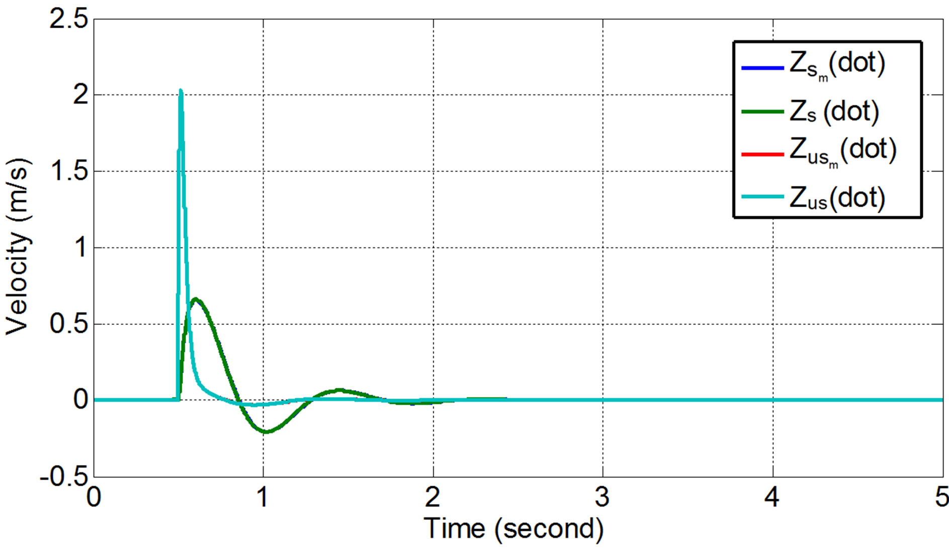
Figure 14. Comparison of velocity responses of the vehicle’s sprung and unsprung mass subjected to step input.
(dotdot)), show similar responses (in a good agreement). The results indicate that applying ML PZT VEH mechanism does not change the vehicle suspension charactersitic/performance. Response of acceleration in Figure 15 show that the maximum amplitude is still in the safety and comfort zone.
The steady state responses of the vehicle were also simulated by exciting the vehicle using sinusoidal (harmonic) input with amplitude of 0.1 m and velocity of 7.54 rad/s. Figures 16-18 show the displacement, velocity and acceleration responses of the vehicle without and with ML PZT VEH mechanism subjected to sinusoidal input/excitation in the time domain (steady state response of the vehicle system). The steady state response also show that applying ML PZT VEH mechanism does not change the vehicle suspension characteristic/performance.
Figure 19 shows the steady state responses of the vehicle without and with ML PZT VEH mechanism in the frequency domain. This figure shows how the responses

Figure 15. Comparison of acceleration responses of the vehicle’s sprung and unsprung mass subjected to step input.

Figure 16. Displacement responses of the vehicle’s sprung and unsprung mass subjected to sinusoidal input.
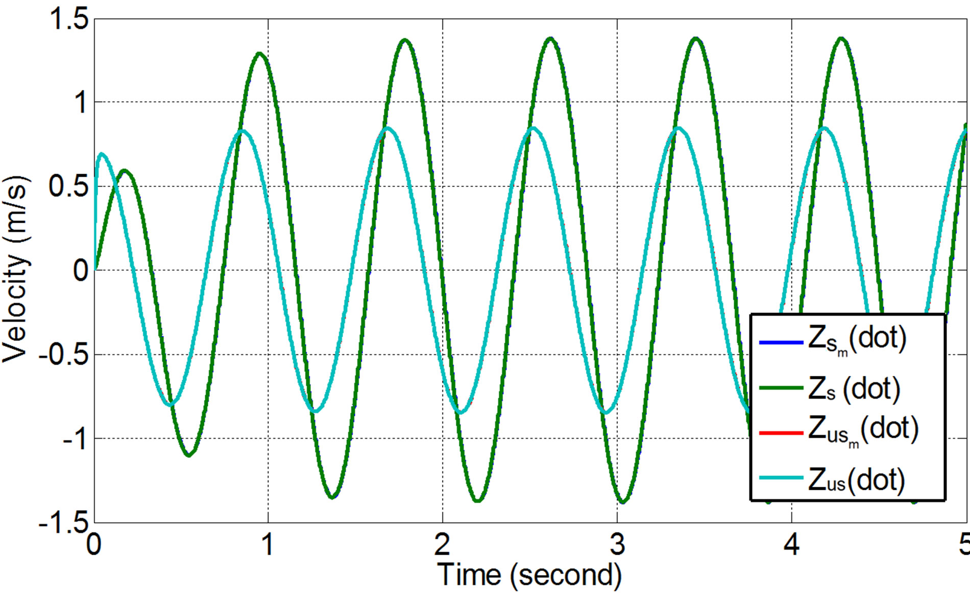
Figure 17. Velocity responses of the vehicle’s sprung and unsprung mass subjected to sinusoidal input.
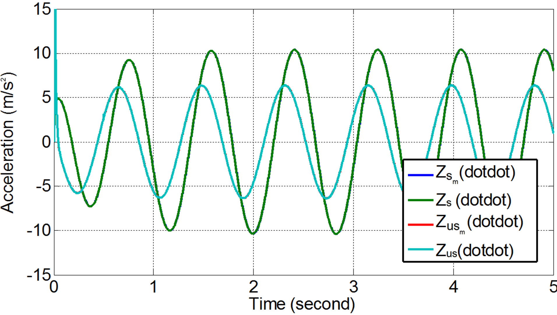
Figure 18. Acceleration responses of the vehicle’s sprung and unsprung mass subjected to sinusoidal input.
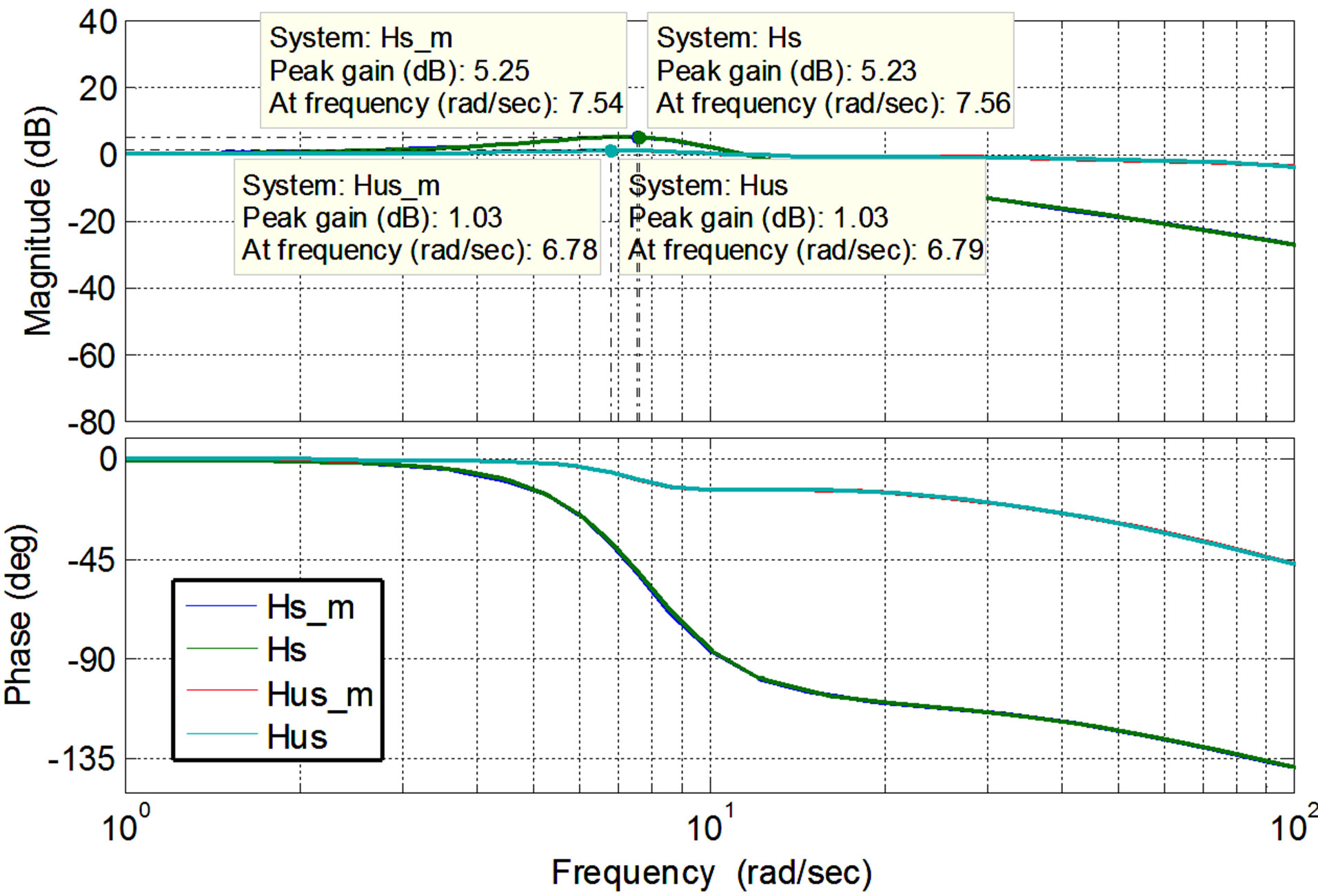
Figure 19. Vehicle responses subjected to sinusoidal input in the frequency domain.
of the vehicle when excitation frequency varies from 0 to 100 Hz. It is shown in the figure that responses of the vehicle without and with ML PZT VEH mechanism are in significantly different, both for sprung and unsprung mass. Peak gain of the unsprung mass (Hus) is 1.03 dB (1.125) occurring at frequency of about 6.78 rad/s or equal to vehicle speed of 38.8 km/h (by assuming that wave length of the road profile is 10 m). Where the peak gain of the sprung mass (Hs) is 5.23 dB (1.825) occurring at frequency of 7.54 rad/s or equal to vehicle speed of 43.2 km/jam.
4.2. The Generated Power from ML PZT VEH Mechanism
Figures 20 and 21 show the steady state responses (generated voltage and power) of the ML PZT VEH mechanism (voltage and power) in time domain when the mechanism is subjected to harmonic input/excitation with amplitude of 0.1 m and frequency of 7.54 rad/s. The result shows that the maximum generated voltage and power from the ML PZT VEH mechanism are 6.23 volt and 1.6 mWatt, respectively.
Figure 22 shows the generated voltage and power of
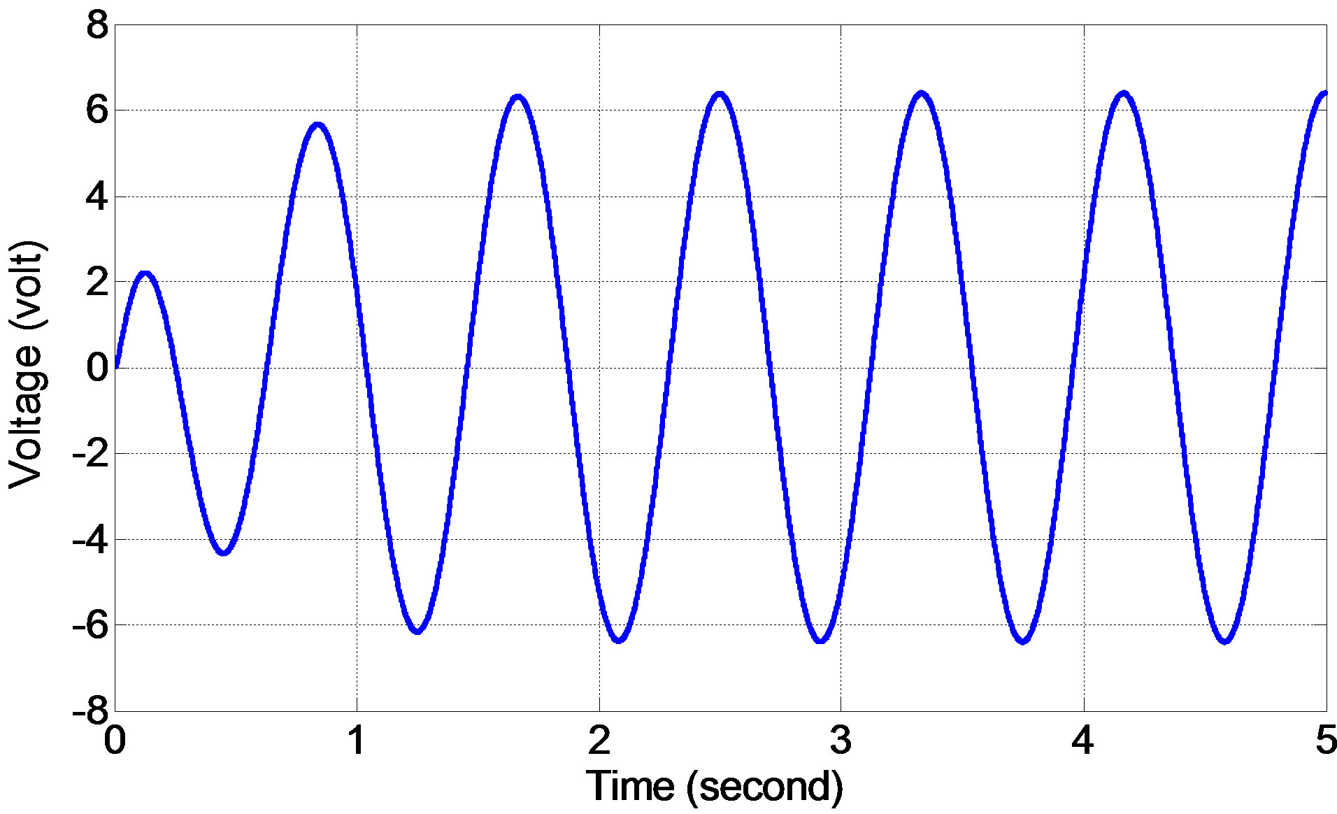
Figure 20. The generated voltage from ML PZT VEH mechanism.
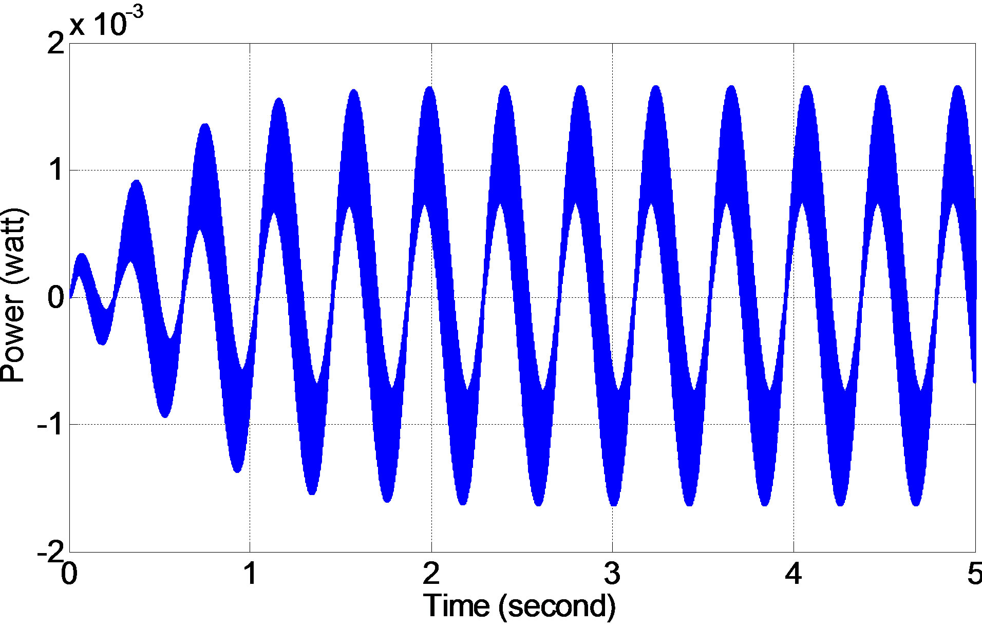
Figure 21. The generated power from ML PZT VEH mechanism.
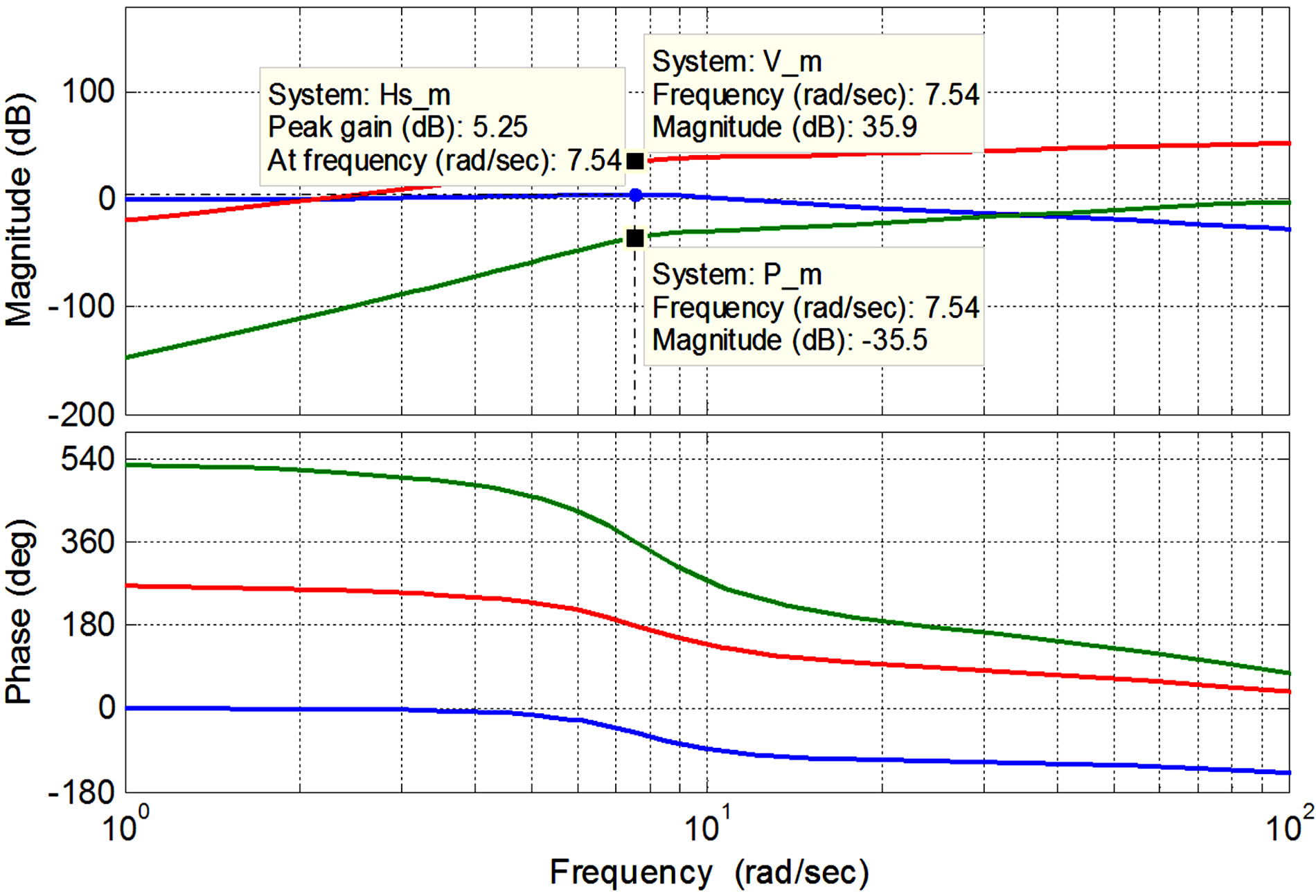
Figure 22. The generated power from ML PZT VEH mechanism in the frequency domain.
the ML PZT VEH mechanism mounted in the vehicle suspension in the frequency domain along with the displacement of sprung mass of the vehicle. It is shown in the figure that the magnification of the generated voltage and power from the ML PZT VEH mechanism are both increasing as the frequency-representing the vehicle speed increase. As shown in the Figure 22, the displacement magnification/amplification of the system reaches its maximum value of 5.25 dB at resonance frequency of 7.54 Hz which is equal to vehicle speed of 43.2 km/h. At resonance frequency, the magnification of the generated voltage and power from the ML PZT VEH mechanism are 35.9 dB (62.37) and –35.5 dB (0.0167), respectively. And at higher frequency than resonance frequency, magnification of the generated voltage and power of the ML PZT VEH mechanism are still increasing although the displacement magnification of the vehicle is decreasing.
The principle of work of the proposed ML PZT VEH mechanism is amplifying the applied force to the PZT by a specific design of the mechanism and combining a single layer PZT into multilayer PZT to increase the produced electricity. The specific design of the mechanism is proposed to amplify the applied force (input) from the spring of the vehicle suspension. This section shows the comparison of the generated power from ML PZT when using and not using the proposed VEH mechanism. Figure 23 show the mathematical model of the vehicle suspension system and the ML PZT with and without the proposed VEH mechanism.
4.3. Comparison of the Generated Power from ML PZT with and without VEH Mechanism
Figures 24 and 25 show the steady state responses (generated voltage and power) of the ML PZT with VEH mechanism (voltage and power) in time domain when the mechanism is subjected to harmonic input/excitation with amplitude of 0.1 m and frequency of 7.54 rad/s which is equal to vehicle speed of 43.2 km/h. The result show that the VEH mechanism can amplify the generated voltage and power 3 times and 7 times of those, the generated voltage and power from the ML PZT without VEH mechanism.
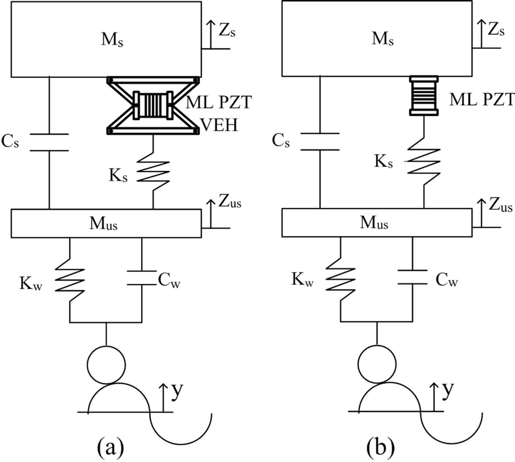
Figure 23. Model illustrating the vehicle mounted with (a) ML PZT VEH mechanism and (b) ML PZT without VEH mechanis.
Figure 26 shows the generated voltage and power of the ML PZT with and without VEH mechanism in the frequency domain along with the displacement of sprung mass of the vehicle. It is shown in the figure that in average, the VEH mechanism can amplify the generated voltage and power 2.75 times and 7.17 times of those, the generated voltage and power from the ML PZT without VEH mechanism. Figure 26 also show the same phenomena as Figure 22.

Figure 24. Comparison of the generated voltage from ML PZT with and without VEH mechanism.

Figure 25. Comparison of the generated power from ML PZT with and without VEH mechanism.
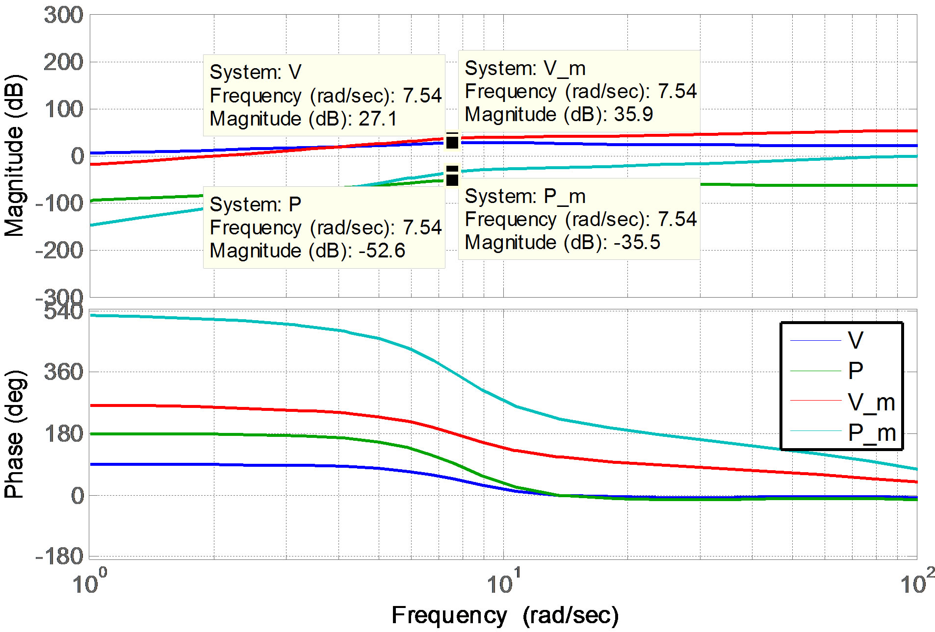
Figure 26. Comparison of the generated power from ML PZT with and without VEH mechanism subjected to sinusoidal input in the freqency domain.
5. Conclusion
This paper reports the design, modeling and analysis of implementing a Multilayer Piezoelectric Vibration Energy Harvesting (ML PZT VEH) Mechanism in the vehicle suspension. Responses of the vehicle before and after implementing ML PZT VEH mechanism were simulated. And the generated power of the ML PZT VEH mechanism was compared with the direct mounting of ML PZT in the vehicle suspension without the VEH mechanism. The simulation result shows that mounting ML PZT VEH mechanism in series with the spring of the vehicle suspension does not change the performance of suspendsion. And the proposed VEH mechanism can produce output voltage of 2.75 and power of 7.17 times bigger than direct mounting to the vehicle suspension.
REFERENCES
- M. V. Melosi, “The Automobile and the Environment in American History,” In: Automobile in American Life and Society, University of Michigan Press, Dearborn, 2004.
- “The Columbia Electronic Encyclopedia,” 6th Edition, Columbia University Press, New York, 2007.
- Y. Suda and T. Shiba, “New Hybrid Suspension System with Active Control and Energy Regeneration,” Vehicle System Dynamic Supplement, Vol. 25, Supple. 1, 1996, pp. 641-654. doi:10.1080/00423119608969226
- Y. Suda, S. Nakadai and K. Nakano, “Hybrid Suspension System with Skyhook Control and Energy Regeneration (Development of Self-Powered Active Suspension),” Vehicle System Dynamic Supplement, Vol. 19, 1998, pp. 619- 634.
- K. Nakano, Y. Suda and S. Nakadai, “Self-Powered Active Vibration Control Using a Single Electric Actuator,” Journal of Sound Vibration, Vol. 260, No. 2, 2003, pp. 213-235. doi:10.1016/S0022-460X(02)00980-X
- Y. Okada, H. Harada and K. Suzuki, “Active and Regenerative Control of an Electrodynamic-Type Suspension,” JSME Internatioanl Journal Series C, Vol. 40, No. 2, 1997, pp. 272-278. doi:10.1299/jsmec.40.272
- Y. Okada and H. Harada, “Regenerative Control of Active Vibration Damper and Suspension Systems,” Proceedings of 35th IEEE Decision and Control, Vol. 4, 1996, pp. 4715- 4720.
- B. L. J. Gysen, J. L. G. Janssen, J. J. H. Paulides and E. A. Lomonova, “Design Aspects of an Active Electromagnetic Suspension System for Automotive Applications,” IEEE Transactions on Industry Applications, Vol. 45, No. 5, 2009, pp. 1589-1597. doi:10.1109/TIA.2009.2027097
- A. Gupta, J. A. Jendrzejczyk, T. M. Mulcahy and J. R. Hull, “Design of Electromagnetic Shock Absorber,” International Journal of Mechanics and Materials in Desigh, Vol. 3, No. 3, 2006, pp. 285-291.
- L. Zuo, B. Scully, J. Shestani and Y. Zhou, “Design and Characterization of an Electromagnetic Energy Harvester for Vehicle Suspensions,” Smart Materials and Structures, Vol. 19, No. 4, 2010, Article ID: 045003. doi:10.1088/0964-1726/19/4/045003
- R. Rajamani and J. K. Hedrick, “Performance of Active Automotive Suspensions with Hydraulic Actuator: Theory and Experiment,” Proceedings of the American Control Conference, Baltimore, June 1994, pp. 1214-1218.
- S. N. Avadhany, “Analysis of Hydraulic Power Transduction in Regenerative Rotary Shock Absorbers as Function of Working Fluid Kinematic Viscosity,” Massachusetts Institute of Technology, Cambridge, 2009.
- Levant Power Corporation, “Levant Power: Revolutionary Genshock Technology,” Product Catalogue. www.levanpower.com
- Bose Company, “Bose Suspension System-White Paper,” 2004. http://www.bose.com
- L. Pickelmann, “Low Voltage Co-Fired Multilayer Stack, Rings and Chips for Actuation,” Piezomechanik, Munich, 2004. www.piezomechanik.com
- M. Arizti, “Harvesting Energy from Vehicle Suspension,” Master of Science Thesis, Tampere University of Technology, Tampere, 2010.
- J.-F. Saillant, S. Cochran, S. Ballandras, R. Berriet and G. Fleury, “Theoretical Effect of Epoxy Interlayer Bonds in Multilayer Piezoelectric Transducers,” IEEE Ultrasonics Symposium, Paisley, 28-31 October 2007, pp. 191-194. doi:10.1109/ULTSYM.2007.59
- Y.-J. Luo, M.-L. Xu and X.-N. Zhang, “Modeling and Simulation of a New Piezoelectric Stack Actuator with Bi-Direction Outputs,” IEEE Symposium on Piezoelectricity, Acoustic Waves and Device Applications (SPAWDA), Xi’an, 10-13 December 2010, pp. 290-295.
- X. Li, M.-S. Guo and S.-X. Dong, “A Flex-Compressive-Mode Piezoelectric Transducer for Mechanical Vibration/Strain Energy Harvesting,” IEEE Transactions on Ultrasonics, Ferroelectrics and Frequency Control, Vol. 58, No. 4, 2011, pp. 698-703. doi:10.1109/TUFFC.2011.1862
- J. Feenstra, J. Granstrom and H. Sodano, “Energy Harvesting through a Backpack Employing a Mechanically Amplified Piezoelectric Stack,” Mechanical Systems and Signal Processing, Vol. 22, No. 3, 2008, pp. 721-734. doi:10.1016/j.ymssp.2007.09.015
Nomenclature:
A: piezoelectric frontal area (m2)
Ar: rubber frontal area (m2)
C: capacitance (F)
d33: piezoelectric charge constant (C/N)
Er: rubber modulus of elasticity (N/m2)
Fm(t): mechanical force (N)
Fe(t): electrical force (N)
 : inertia force of the pusher (N)
Fr : rubber force (N)
 : inertia force of the ML PZT
 : stiffness force of the ML PZT
Hs: peak gain of sprung mass without VEH mechanism
Hus: peak gain of unsprung mass without VEH mechanism Hs_m: peak gain of sprung mass with VEH mechanism
Hus_m: peak gain of unsprung mass with VE mechanism Kr: rubber stiffness constant (N/m)
 : total thickness PZT (m)
 : rubber mass (kg)
 : ML PZT mass (kg)
n: number of PZT layer
 : power (watt)
P: power without VEH mechanism (watt)
P_m: power with VEH mechanism (watt)
Q: electric charge (C)
R: resistance (ohm)
 : rubber thickness (m)
t: PZT thickness (m)
 : displacement of ML PZT(m)
 : voltage (volt)
V: voltage without VEH mechanism (volt)
V_m: voltage with VEH mechanism (volt)
 : young’s modulus of PZT (N/m2)
 : displacement of pusher (m)
 : deflection of rubber (m)
 : excitation frequency (rad/s)