Engineering
Vol.4 No.12(2012), Article ID:25850,4 pages DOI:10.4236/eng.2012.412109
A Thermochemical Process Using Expanding Plasma for Nitriding Thin Molybdenum Films at Low Temperature
1Centre Européen de la Céramique, Limoges, France
2Ecole des Mines, Parc de Saurupt, Nancy, France
3Université de Limoges, Limoges, France
Email: isabelle.jauberteau@unilim.fr
Received August 28, 2012; revised September 26, 2012; accepted October 11, 2012
Keywords: Thermochemical Process; Expanding Plasma; Thin Films; Molybdenum Nitrides; Molybdenum Oxides; NHx Species
ABSTRACT
The mechanical and chemical properties of transition metal nitrides are very attractive for numerous industrial applications. Thin nitride films are expected to be good diffusion barrier in microelectronic devices. Nitrogen diffuses into the whole thickness of the molybdenum film heated at low temperature and exposed to expanding plasma of (Ar-N2-H2) compared with pure N2 plasma. NHx species in the plasma are produced by different homogeneous or heterogeneous reactive mechanisms that results in an expansion of the plasma compared with pure N2 plasma. NHx species and probably H atoms improve the transfer of nitrogen into the metal by preventing the formation of MoO2 oxides which act as a barrier of diffusion for nitrogen.
1. Introduction
The attractive mechanical and chemical properties make transition metal nitrides and especially molybdenum nitrides very suitable for various applications.
Molybdenum nitrides have high wear resistance, hardness values ranging from 28 to 34 GPa compared with values ranging from 18 to 24 GPa for TiN and CrN, that makes Mo-N compounds as potential materials for applications in tribology. They also have high melting point, good chemical stability, low electrical resistivity; they can be used as gate electrode materials for high-k gate dielectrics [1-3]. Their surface oxides (MOx) of lamellar structure offer good lubricating properties at high temperature. Molybdenum nitrides are expected to be interesting in micromachining technology [4]: high temperatures are needed to deposit polycrystalline silicon as well as for the activation of dopants. The use of molybdenum nitrides instead of silicon allows the temperature of deposition to decrease as well as the electrical resistivity which is equal to 180 mW cm for Mo2N and several hundreds of mW cm for silicon. Molybdenum nitrides also exhibit very interesting catalytic properties which can be compared with those of noble metals for hydroprocessing, hydrogenolysis, hydrogenation and [H2-N2] reactions [5-7]. Mo2N is catalytically active for NO reduction in presence of hydrogen; the NO conversion on Mo2N is 89% at 723 K and remains constant for 10 h. Transition metal nitrides are also expected to be good barriers against oxygen diffusion. In Josephson circuits based on Nb/AlOx/Nb junctions, the electrical characteristics as well as the superconductivity of Nb wiring are degraded by annealing even at a temperature of 473 K that prevents from using other processes in semiconductor devices which require higher temperature annealing [8]. A 3 to 5 nm thick niobium nitride prevents oxygen from diffusing into the metal that improves the annealing stability up to 623 K and allows new process techniques to be used at higher temperatures such as bias sputtered SiO2 insulators. Molybdenum nitride films are also expected to be diffusion barriers in microelectronic devices and especially in Al-Si and Cu-Si contact structures [9-11]. Molybdenum nitrides crystallize in five phases [10]: δMoN of hexagonal structure, γMo2N of face-centered cubic structure of NaCl type where the Mo atoms occupy the positions of the face-centered lattice whereas nitrogen atoms occupy half of the total octahedral sites, b1Mo2N and b2Mo2N of body-centered tetragonal structure and b3Mo16N7 of tetragonal structure. However numerous authors report only three phases for molybdenum nitrides which are: δMoN, bMo2N and γMo2N [2,12,13]. Amorphous structures have also been obtained for the purpose of avoiding the influence of grain boundaries since they are fast diffusion paths for Cu in diffusion barriers [4,14]. Molybdenum nitrides can be made by various plasma processes involving DC, magnetron or rf plasma [2-4,10,11] CVD [9] and even nitrogen ions implantation [15-17]. In this paper, we present a chemical vapor deposition (CVD) process using expanding plasma activated by microwave to nitride thin molybdenum films at low temperature; about 673 K. Low temperature processes are needed to prevent components as thin metallic films coated on glass substrates from damaging. This process has been successfully used to deposit thin DLC layers on Si substrates and carburize steels [18,19]. Expanding plasma are very useful to process on a larger surface by carrying reactive species far from the center of the discharge. We describe the thermochemical process using plasma activated by a microwave discharge and especially the way to create expanding plasma containing active species as well as the chemical reactions occurring in the gas phase. The diffusion of nitrogen into the molybdenum films is discussed and correlated to the composition of plasma and especially hydrogen species such as excited and ionized nitrogen-hydrogen radicals; NHx<3 or atomic hydrogen which are expected to play a great role on the reactivity of surfaces. Such works conducted both in plasma and surface layers of the metal film attempt to highlight the ill-known phenomena occurring at the interface of plasma and solid surface.
2. Conditions of Formation of an Expanding Plasma
In expanding plasma, the gaseous species such as ions, radicals…are produced within the microwave discharge and carried along the discharge up to the surface of the substrate. The power of the electromagnetic wave (frequency equal to 2.45 GHz) absorbed by plasma is mainly transferred to the electrons and then to the other gaseous species by inelastic collisions.
The absorbed power is written:
 (1)
(1)
where Q is the power required to maintain one electron in the discharge and ne is the density of electrons. The conditions of propagation of the electromagnetic wave outside the surface wave launcher are satisfied when the density of electrons is above a critical value. Since w is the frequency of microwave and wp is the frequency of resonance of electrons in the plasma. So:
 (2)
(2)
where wp is equal to (nee2/mee0)1/2 and ev is the relative permittivity in the silica tube, ne, e and me are the density, the charge and the mass of electrons, respectively whereas e0 is the permittivity of vacuum. Since w/2π is equal to 2.45 GHz, the conditions of propagation of the electromagnetic surface wave is realized for:
 (3)
(3)
So, expanding plasma occurs when the density of electrons is larger than 3.6 × 10¹⁷ m–3. Since, the surface wave launcher of the reactor is connected to the quartz tube, this value has been determined for a known permittivity, ev. However, in reality, the plasma is expanded outside the quartz tube in the stainless steel part where the value of the permittivity is unknown. Moreover, according to previous works conducted on Ar gas with emission spectroscopy, the intensity of emission lines of some species increases on the edge of plasma [20]. The electromagnetic wave seems to propagate on the surface of plasma, drawing a bright cone inside the stainless steel part of the reactor. Since the critical value of the density of electrons depends on the local electrical parameters, the as-determined value is probably not valuable in that case. It is worth noting that previous measurements carried out in (Ar-N2-H2) plasma at distances of 10 cm from the center of the discharge give lower values for the density of electrons which is closer to 1016 m–3 [21]. Further investigations conducted with emission spectroscopy will highlight the formation of expanding plasma. Since inelastic collisions occurring between molecules and electrons lead to a decrease of the density of electrons, the addition of low amounts of molecular gas in an inert gas as Ar allows high density of electrons to be maintained in plasma. The density of electrons in Ar gas ranges between 0.5 and 1 × 10¹⁶ m–3. The addition of CH4 molecular gas in Ar results in a strong decrease of the expansion in length of plasma because of the increasing number of collisions between electrons and molecules that decrease the density of electrons [18]. The mean values of electron energy have also been investigated in various plasma. They are equal to 0.6 and 0.4 eV for pure Ar and N2 gas, respectively and they range from 0.5 to 0.7 eV in ternary (Ar-N2-H2) gas mixtures for microwave power ranging between 100 and 400 W. The energy of ions is rather low and equal to 0.1 eV in the plasma and could be larger in the sheath surrounding the substrate. So, in contrast with numerous plasma treatments where the impinging energetic ions have a strong sputtering effect on passive oxide or carbide layers which remain at the surface of materials and act as a barrier of diffusion for reactive species of plasma, the reduction of oxides and carbides is mainly due to hydrogen species in our reactor.
3. Thermochemical Treatment in Expanding Plasma
The reactor consists of a fused silica tube (external and internal diameter of 24 and 20 mm) passing throw a surface wave launcher where the discharge is produced (Figure 1). As previously discussed, the discharge is expanded in a stainless steel part containing the substrate holder which can be moved along the z axis of the reactor from positions close to the center of the discharge to positions far in the post-discharge. This kind of geometry allows the impinging species to be selected since the reactive species have short time of life and they are easily recombined in the plasma they are therefore mainly found at distances close to the center of the discharge. The substrate holder can be heated up to 1173 K. The temperature is controlled by means of a two colors pyrometer (IRCON mirage). The discharge is switched on with a power supply SAIREM GMP 12 kE operating between 0 and 1200 W. The total pressure in the range of 0.13 to 1.3 kPa is kept constant using an Alcatel roots blower pump (70 - 700 m3 h–1) which maintains a gas drift velocity of about 5 - 100 ms–1. The base pressure is kept constant at 10–4 Pa between nitriding treatments by using a turbomolecular pump.
4. NxHy Radicals and Molecules Produced in Ar-N2-H2 Expanding Microwave Plasma
The most famous method to produce ammonia from nitrogen and hydrogen has been proposed by Haber in 1909 [22] and is known as the “Haber process”. Ammonia is produced on an iron catalysis surface at relatively low temperatures (573 K to 823 K) and high pressures (15 to 25 MPa). The reaction yield is low (15%) but residual gases can be recycled, increasing thus the efficiency up to 98%. Similar methods have been experimented using an iron catalytic electrode, placed within an N2-H2 discharge or in the discharge afterglow to produce NH3 [23-25] or hydrazine [26] or for nitriding treatments of iron [27]. Different discharges have been tested like dc and ac discharge current, rf, and microwave discharge. The reactive processes involved in NxHy synthesis or nitriding treatments of metallic pieces have been studied theoretically by means of numerical models [28,29] or
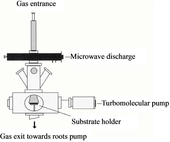
Figure 1. Expanding plasma.
experimentally [30-33]. According to Gordiets et al. [28, 29] the large NH3 concentration measured in N2-H2 discharge cannot be explained only by volume reaction. Surface reaction process must be involved in the model to explain the large amount of NH3.
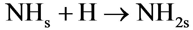
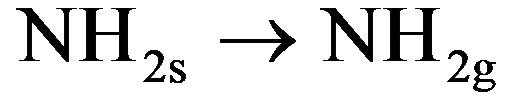
The surface mechanism takes into account the physical adsorption and desorption of radicals (N, H, NH and NH2), the chemical adsorption and desorption of previous radicals, the surface diffusion of physisorbed species, and the chemical reaction of chemisorbed species with gas (Eley-Rideal mechanisms) or with physisorbed species (langmuir-Hinshelwood mechanisms). Considering the efficiency of different processes, the reactive mechanism can be simplified as follows [30]:
 (4.1)
(4.1)
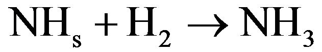 (4.2)
(4.2)
 (4.3)
(4.3)
 (4.4)
(4.4)
In these reactions NHxs and NHx species are adsorbed on the catalytic surface. According to Gordiets et al. [28,29] the main channels producing NH3 are surface reactions (4.1) and (4.2). The volume reaction in gas is less efficient. Moreover NH3 is dissociated in the discharge by reactions with ions or electrons. Consequently the concentration of NH3 is more important in the afterglow than in the discharge. Assuming that the NH2 flux is lower in post-discharge than H2, N or H flux, the reaction between NH2 gas and adsorbed H producing NH3 (NH2 + Hs→NH3) can be neglected compared to the two previous ones (4.1) and (4.2). Mass spectrometer analysis has been performed at 20 cm above the microwave discharge exit working at a power of 150 W and pressures ranging from 10 to 100 Pa. The results show that the main species are detected at m/q = 1, 2, 14, 15, 16, 17, 18, 28, 30, 40. These peaks correspond to H+, H2+, N+, NH+, NH2+, NH3+ (or OH+), H2O+ (residual water), N2+, N2H2+, O2+ (residual oxygen) and Ar+, respectively. No peak are observed at m/q equal to 32 and no significant change is observed for m/q equal to 18 when the discharge is on and off, this suggests that N2H4+ and NH4+ are not detected. All these species are produced in the bulk plasma or on the reactor wall, resulting in the various homogeneous or heterogeneous reactive mechanisms. Using the previous simplified mechanism (reactions (4.1) to (4.4)), the reaction rate constants have been determined by adjusting a simple model to experimental results obtained in Ar-N2-H2 gas mixtures by means of mass spectrometry [30,31]. Figure 2 displays the relative density NHx/NH3 versus H2 injected in the Ar-1.3%N2 gas mixture. The adjustment is obtained assuming that the relative density NH/N is equal to 1.9 at 10% of H2 injected in the dis-
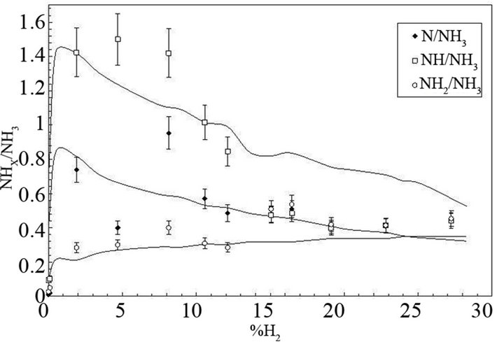
Figure 2. Relative concentration of NHx(0,1,2) radicals (NHx/ NH3) versus %H2 injected in Ar-1.3%N2. The experimental results are compared with the theory.
charge. A good agreement between the experiments and the theory is obtained for k1 ranging from 1 × 10–17 to 2 × 10–17 m3·s–1, k2(NHs) ranging from 0.035 to 0.045 m·s–1, k3(NHs) ranging from 9 to 11 m·s–1 and ksg ranging from 0.3 to 0.35 m–1·s–1. The results obtained in Ar-33.3%N2 gas mixture are displayed in Figure 3. The NHx density is much lower than in Figure 2 and the NH2 radical density becomes larger than the NH radical density. As expected, the best fit between the theory and the experiments is obtained for the same values of k1 and ksg but for larger k2(NHs) and k3(NHs) values compared with the first gas mixture. In that case, the values increase by a factor 5. This difference is probably due to the increase of the NHs density chemisorbed on the reactor wall with increasing N2 concentration in Ar gas. From these values it is possible to determine the recombination coefficient γ which is defined as the ratio of the number of reacting species per second to the number of atoms striking the surface per second. This coefficient can be written assuming a cylindrical geometry, γ = 2kR/v; where k, R and v are the reaction rate constant value, the radius of the reactor and the mean thermal velocity of species, respectively [34]. In microwave plasma, the H atom density ranges from 1019 to 1020 m–3 according to the dissociation yield ranging from 1% to 10%. Considering H atoms concentration equal to 1 × 10¹⁹ m–3, the values γ are equal to 4.12 × 10⁻⁴, 4.91 × 10⁻⁶, 7.93 × 10⁻⁴ for reactions (4.1), (4.2) and (4.3), respectively. These results show that when H atoms are lost on the reactor wall, a large part of those atoms produces NH2 which are adsorbed on the wall via reaction (4.3) and a smaller part produces NH3 via reaction (4.1). Helden et al. [32,33] have studied NHx synthesis in N2-H2 cascaded arc plasma working from 20 to 100 Pa in the vessel and at 2 to 8 kW, in reactor configurations of different surface/volume ratios S/V equal to 14 m–1, 16 m–1 and 4 m–1, which are smaller than the S/V ratio used in our experiments (S/V = 40 m–1). Investigations are performed by means of cavity ring-down absorption spectroscopy on NH and NH2 radicals and mass spectrometry measurements are performed in the background of the reactor in the case of NH3. These authors confirm that NH3 is mainly produced by heterogeneous reactions on the wall reactor and that the density of NH3 increases with increasing S/V ratio. NH3 molecules involved in homogeneous reactive processes producing NH or NH2 are reintroduced in the reaction volume until the exit of the cascaded arc because of the recirculation of species due to eddies within the reactor. According to these authors, the main reactive mechanisms which produce or destroy NH and NH2 radicals in the plasma volume are the following:
1) NH is mainly produced by charge-transfer reactions between recirculating NH3 and Ar+ ion in the discharge with subsequent dissociative recombinations of molecular ions with electrons:
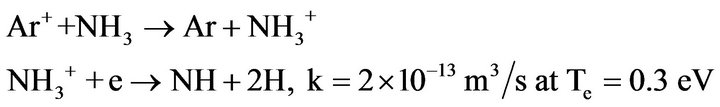
(4.5)
The last step can also produce NH2 in smaller amounts:
 (4.6)
(4.6)
2) Other mechanisms efficiently produce NH radicals in the discharge or in the afterglow, by reactions of N atoms or N+ ions with H2. These reactions are especially efficient in the case of metastable species N(2D) or vibrational excited hydrogen [28]. They are:
 (4.7)
(4.7)
 (4.8)
(4.8)
The reactions between NH2 radical and H or N are less efficient.
3) NH is mainly destroyed by diffusion on walls, or recombination with N or H atoms:
 (4.9)
(4.9)
 (4.10)
The recombination of NH with itself is less efficient.
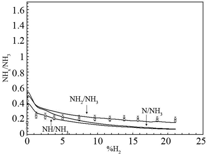
Figure 3. Relative concentration of NHx(0,1,2) radicals (NHx/ NH3) versus %H2 injected in Ar-33.3%N2. The experimental results are compared with the theory.
4) NH2 is produced in the discharge by reaction (4.6) and in the afterglow mainly by:
 (4.11)
According to Gordiets et al. [28], the reaction of NH3 with N2 (A3Su+) and N (2D) are also very efficient to produce NH2 radicals. The reaction rate constants are k = 1.6 × 10⁻¹⁶ m3·s–1 and 1.1 × 10⁻¹⁶ m3·s–1, respectively.
5) NH2 is destroyed by recombination with atoms or radicals in the afterglow and by diffusion on the wall. In the case of a reactor configuration with a large S/V ratio, the dominant recombination mechanisms are the diffusion on the wall with subsequent heterogeneous reactions from (4.1) to (4.4). At small S/V ratio the volume reaction in afterglow will be the dominant process. As previously seen, NH3 is easily destroyed in the discharge by reactions with ions and consequently the density of NH3 is generally larger in afterglow than in the discharge. The yield of produced NHx can therefore be increased using a reactor configuration promoting the recirculation of gas between the discharge and the background of the vessel. According to C. I. Butoi et al. [35] heterogeneous reactive mechanisms are also efficient to produce NH and NH2 radicals. Three main reactive pathways can occur. They are:
1) The dissociation of NH3 on the reactor wall
 (4.12)
2) Eley-Rideal type reaction
 (4.13)
3) Langmuir-Hinshelwood type reaction
 (4.14)
In this scheme, NH2 is not only produced in the discharge or in afterglow by homogeneous or heterogeneous reaction of NH3 with charged particles, radicals or surface, but also by heterogeneous recombination of NH on the wall. As expected, an increase of NH density gives rise to the increase of NH2 produced on the reactor wall. According to Nagai et al. [36], the electron density increases within the discharge when 30% N2 is added to H2 because the total ionization cross section of N2 producing mainly N2+ (1.242 × 10⁻²⁰ m2 at 30 eV [38,39]) is larger than the total ionization cross section of H2 producing mainly H2+ (0.693 × 10⁻²⁰ m2 at 30 eV [38,39]). The increase of the electron density leads to the increase of the H atoms density and ions bombardment and an increase of the etching rate probably due to H atoms. Such increase of the electron density have been observed in microwave plasma produced in ternary gas mixtures [31] as Ar-8%N2-10%H2 and Ar-25%N2-25%H2. In binary mixture the electron density drastically decreases when more than 1% of H2 or 5% of N2 is mixed to Ar, whereas electron density in ternary gas mixtures is as large as in pure argon when up to 50% of molecular species N2 and H2 is mixed to argon. This behaviour can be ascribed to the formation of NHx species in the gas mixture. The ionization threshold and the ionization cross section of these species at 30 eV are reported in Table 1. It can be seen that NHx species have a lower ionization threshold than N2, H2 or Ar. Ionization is more efficient at low electron energy for NHx than for N2, H2 or Ar and the partial ionization cross section of NHx producing NHx+ is nearly equal to the values of the total ionization of N2 or H2. Moreover, NHx species give rise to direct and dissociative ionization processes and the total ionization cross section value is the sum of all partial ionization cross sections producing NHy+,with y ≤ x. In the case of NH3, the total cross section value is larger than the ionization cross section of Ar, H2, N2 (see Table 1) and similar effects are expected in the case of all NHx radicals which are produced. Consequently, Ar-N2-H2 ternary gas mixtures producing a large amount of NHx species have a larger electron density and a better plasma expansion in the reactor than Ar-N2 or Ar-H2 binary gas mixtures. In Ar-N2-H2 gas mixtures, N2H2 (diimide molecules) are also produced in small amounts whereas N2H4 has not been observed in our experiments. The relative density N2H2/NH3 versus %H2 injected in Ar-9%N2 (empty square) and Ar-36%N2 (full circle) are displayed in Figure 4. The density of N2H2 molecules remains lower than 10% of NH3. Results show that a maximum of diimide is produced in the two gas mixtures at about 5% of H2 injected in the plasma. According to Stothard et al. [40] two main reactions pathway occurring in the gas volume produce diimide molecules, they are:

Table 1. Ionization threshold and ionization cross section (partial and total at 30 eV) [37-39].
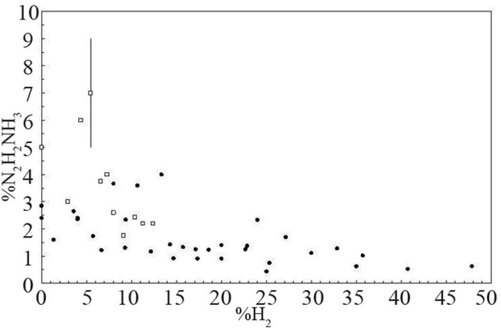
Figure 4. Relative concentration of diimide (N2H2/NH3%) versus %H2 injected in Ar-9%N2 (empty square) and Ar- 36%N2 (full circle).

(4.15)
This reaction is exothermic .
.
And the more efficient process:
 (4.16)
However, the surface reactions can also be efficient to produce diimide molecules in a reactor configuration with a large S/V ratio. According to Huang et al. [41], the reaction NHs+NHs→N2H2 can be the primary mechanism for diimide molecules formation. This process is enhanced by co-adsorbed Hs which stabilizes NHs on Ni(100) surface. When H2 is mixed to Ar-N2 in very large amount, the surface sites are saturated with Hs and recombination surface mechanisms of NHs producing N2H2 are inhibited. This behavior could explain the results displayed in Figure 4, the maximum of efficiency is obtained for 5% of H2 mixed to Ar-N2. In the case of hydrazine, it can be produced by wall recombination of NH2 radicals (Langmuir-Hinshelwood mechanism),
 (4.17)
The reaction is more exothermic  than reaction (4.15) and heterogeneous processes are necessary to stabilize N2H4 molecules, whereas N2H2 molecules can be produced directly by the homogeneous reaction (4.15) in the gas phase. Because of the low NH2 flux impinging the wall, hydrazine is generally produced in small amounts so, it has not been observed in our experiments.
5. Surface Reactivity of Thin Molybdenum Films in (Ar-N2-H2) Plasma
In this part, we present results on the composition and structure of very thin films of molybdenum (thickness equal to 100 - 200 nm) coated on Si (100) substrates and exposed to (Ar-N2-H2) plasma of various compositions. The contents are expressed as a percentage of the total volume of gas. The molybdenum films are deposited on Si (100) wafers in an electron beam evaporator. Molybdenum pellets, 99.95% pure are evaporated in Ar gas at a pressure of 0.5 Pa. The Si wafer is polarized at –400 V and heated up to 673 K. Such experimental conditions allow oxygen in the ingot to be lower and lead to a good adhesion of molybdenum films on wafers. The treatment is carried out in expanding plasma at temperatures as low as 673 K. As previously seen, such conditions of temperature prevent any damage of the substrate in the case of films coated on glass substrates that would lead to a decrease of the adhesion of the film on the substrate. The results are compared with those obtained for substrates heated at 873 K. All experiments are carried out at a microwave power and a pressure of 400 W and 0.13 kPa, respectively.
5.1. The Means of Investigation
The chemical composition of the nitride layers is studied by secondary neutral mass spectrometry (SNMS). The measurements are carried out in a secondary ion mass spectrometer LAB from VG instrument. The analysis of depth profiles is undertaken by means of Ar+ primary beam of ions (8 keV). The size of as-formed craters is of (500 × 500) μm2. The sputtered neutrals are ionized by a thermoionic filament. The structure of compounds which are formed in the nitride layers are investigated by Raman spectroscopy. The Raman spectra are recorded in backscattering geometry by using a Jobin-Yvon spectrometer (64000 model) equipped with a CCD cooled by a flux of liquid nitrogen up to 140 K in order to reduce the thermal noise. The exciting line which is produced by an Ar+ laser (540.532 nm) is focused on to the sample using a microscope (×50), the size of the spot is equal to about 1 μm. The power of the laser is adapted to prevent any damage on the sample. The wave numbers range between 10 and 20000 cm–1. All spectra are averaged, so the signal intensities are representative of the treated material. The morphology of the film is detected by atomic force microscopy (AFM). The measurements are carried out by means of a Digital Instruments NanoscopeII operating in constant force mode. The signal is fitted by subtracting a “polynomial plane” which consists of a surface whose cross section is a second order polynomial in one axis and a horizontal line in the other axis. Some x-ray diffraction measurements have also been performed in a theta- 2theta SIEMENS D5000 diffractometer using CuKα radiation in sol-X energy dispersive detector, the configuration of the system is the classical Bragg-Brentano geometry. However, because of the low thickness of the molybdenum films compared with the silicon substrate, most of the results were unreliable, nonetheless, some of them are discussed.
5.2. Composition and Structure of Films
5.2.1. Untreated Molybdenum Films
The secondary neutral mass spectrometry (SNMS) analysis of the untreated molybdenum film is displayed on Figure 5(a). The oxygen amount is equal to about 5% in the whole thickness of the metal film. No nitrogen and carbon are identified in the limit of the accuracy of the method. Molybdenum and silicon signals are also registered. Oxygen is identified in the form of MoO3 oxide on the Raman spectrum (Figure 5(b1)). It consists of a broad band with two maxima at 848 and 996 cm–1 corresponding to an amorphous structure, since well-crystallized MoO3 of orthorhombic structure consists of two main bands at 820 and 996 cm–1 and bands of lower in-
 (a)
(a)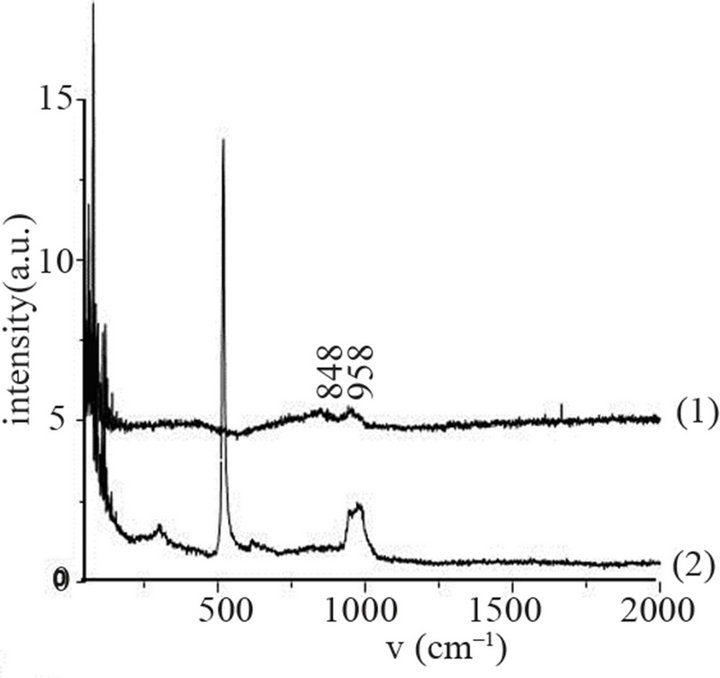 (b)
(b)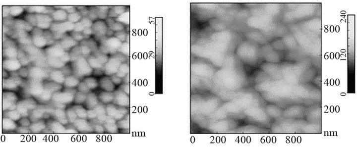 (c)
(c)
Figure 5. Mo, Si, N, O and C SNMS signals (a), Raman scattering spectra (b1) compared with Si substrate (b2), two types of morphology of surface (c) and (d) of untreated molybdenum films (see text).
tensities identified at shorter wavenumbers [42-44]. The Raman signal corresponding to the Si substrate does not appear (Figure 5(b2)). The morphology of the surface consists of small grains of about 50 nm in size. The roughness of the film varies in function of the molybdenum film coated on the Si wafer. On Figures 5(c) and (d), two films of roughness equal to 4.3 and 15.3 nm, respectively are displayed. The film of higher roughness consists of agglomerates. In previous works, the untreated film consists of grains of pure molybdenum of tetragonal crystallographic structure [21].
5.2.2. Molybdenum Films Exposed to Pure N2 Plasma
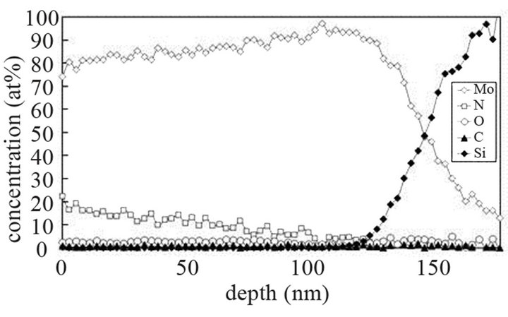
The molybdenum films are heated at 673 K and then exposed to pure N2 plasma for 15 min. As previously seen, the influence of the impinging gaseous species in the plasma is investigated by moving the substrate along the z axis of the reactor from positions close to the center of the discharge to positions far in the post-discharge. The SNMS signal of nitrogen corresponding to the substrate located at 9.5 cm from the discharge center is displayed on Figure 6(a). The nitrogen slightly diffuses into the molybdenum films up to a depth of about 40 nm. An unexpected strong enhancement of the oxygen signal is also detected in the same area. The nitrogen and oxygen amounts are equal to about 2 and 25 at%, respectively at a depth of 25 nm. This huge amount of oxygen could arise from the desorption of oxygen and/or water from the walls of the reactor in contact with the plasma since the amount of oxygen corresponding to the untreated films is quite lower. Oxygen diffuses into the metal layers and forms a barrier which prevents nitrogen from diffusing deeper into the metal film. In contrast to this result, only very slight amounts of nitrogen and oxygen are transferred into the films located at 15.5 cm from the discharge center, the concentration values are quite within the range of the detection limit of the method (Figure 6(b)). This result is correlated to the geometry of pure N2 plasma which remains in a confined space around the center of the discharge: the density of electrons of 0.16 × 10¹⁶ m–3 in pure N2 plasma is lower than the one corresponding to pure Ar plasma which ranges from 0.5 to 1 × 10¹⁶ m–3 [20]. So, the substrate located at 15.5 cm from the center of the discharge is probably exposed to the postdischarge where the amount of active species is low. The results from Raman spectroscopy are quite consistent with those of SNMS, since the Raman spectrum corresponding to an exposure at 9.5 cm from the discharge center displays thin and broad bands in the range of wavenumbers between 199 and 739 cm–1. These Raman bands are assigned to MoO2 oxides of monoclinic structure [42,45, 46] (Figure 6(c1)). MoO3 oxides of amorphous structure are still detected at wavenumbers of 848 and 964 cm–1 that corresponds to the remaining oxides in the untreated molybdenum film. As we have previously seen, oxygen desorbs from the wall of reactor in contact with the N2 plasma and leads to the formation of MoO2 inside the film. So, the active species have a reducing activity since MoO2 is formed instead of MoO3. Other broad bands are also identified on the spectrum at 1303 and 1599 cm–1 and correspond to the formation of DLC. Its amount is low since this compound has a high sensibility to the laser line. The formation of DLC could be assigned to a decomposition mechanism of the contamination layers remaining on the substrate holder. Once the carbon has been transferred to the surface of the metal film, it is transformed into DLC compound. Such an effect has already been observed in former works [47]. These results are compared with those obtained at a substrate temperature of 873 K and located at 12.5 cm from the center of the discharge to prevent any damage on the quartz tube (Figure 6(c2)). All features corresponding to MoO2, MoO3 as well as DLC are still detected. The concentration of DLC increases with temperature increasing. Only the broad band
 (a)
(a)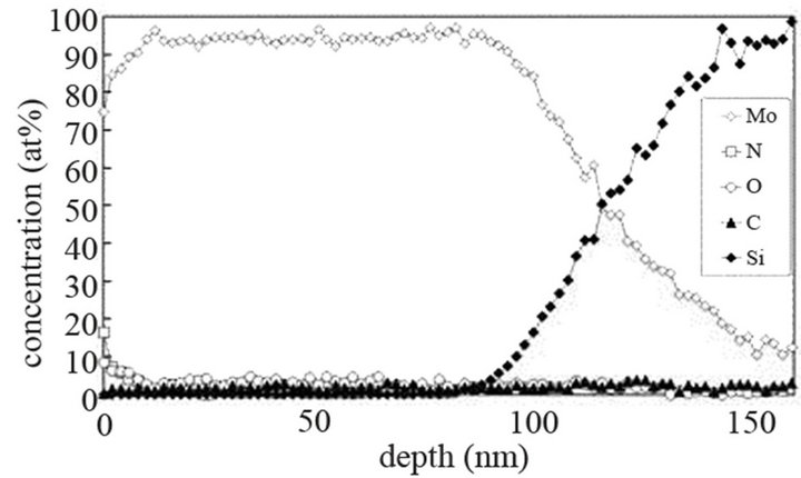 (b)
(b)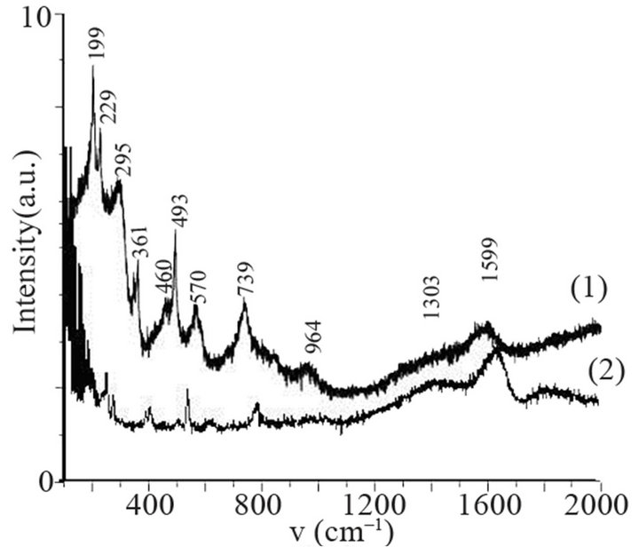 (c)
(c)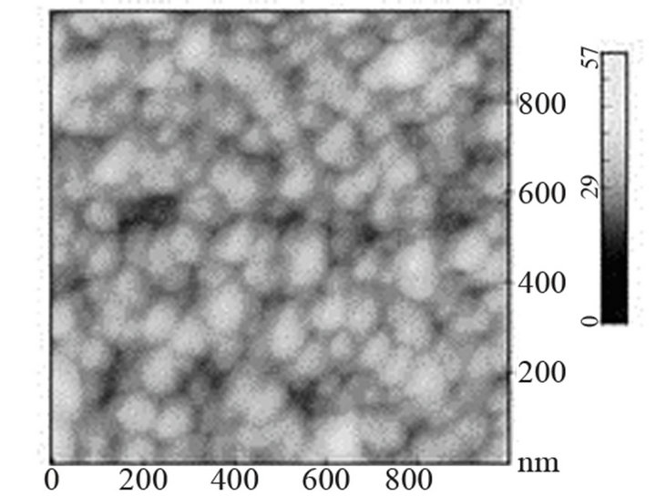 (d)
(d)
Figure 6. Mo, Si, N, C and O SNMS signals of molybdenum films heated at 673 K and exposed to pure N2 plasma at 9.5 cm (a) and 15.5 cm (b) from the centre of the discharge, Raman scattering spectra of molybdenum films heated at 673 K (c1) and 873 K (c2) and exposed to pure N2 plasma, morphology of the surface of molybdenum films heated at 673 K and exposed to pure N2 plasma (d).
identified in the wavenumbers range from 100 to 300 cm–1 on the spectrum corresponding to the film heated at 673 K has disappeared. In the literature, such a Raman feature is reported for TiN, ZrN, TiAlN, TiZrN and TiCN compounds [48]. Because of their symmetry, the compounds of fcc structure do not display any first-order Raman spectrum. However, the presence of impurities or defects in the lattice as nitrogen ion vacancies leads to the relaxation of selection rules by reducing the effective symmetry and induces a first-order spectrum which contains broad bands that reflect the vibrational density of states. Such a band has also been identified on the Raman spectrum recorded on γMo2N of cubic structure prepared by high pressure-high temperature synthesis [49]. The Raman feature corresponding to γMo2N consists of two large bands at 150 and 240 cm–1. They are due to N3– vacancies appearing within the molybdenum nitride of fcc structure. The morphology of the molybdenum surface heated at 673 K and exposed to N2 plasma during 15 min consists of small grains ranging in size from 50 to 100 nm like the untreated surface (Figure 6(d)). However, a slight decrease of the size of the grains as well as a slight enhancement of the roughness which is equal to 5.4 nm is detected, compared with the untreated molybdenum film.
5.2.3. Molybdenum Films Exposed to (Ar-N2-H2) Plasma
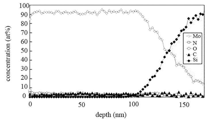
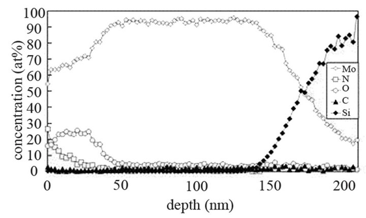
The molybdenum films are heated at 673 K and exposed to (Ar-25%N2-30%H2), (Ar-8%N2-10%H2) and (Ar-30% H2-12%H2) for 15 or 40 min at 9.5 cm or 15.5 cm from the center of the discharge. As indicated on SNMS results (Figure 7(a)), nitrogen diffuses into the whole molybdenum film exposed to (Ar-25%N2-30%H2) for 15 min. The amount of nitrogen is equal to about 20 at% in the surface layers of films and progressively decreases up to the molybdenum-silicon interface where the amount of nitrogen corresponds to that of untreated molybdenum. Moreover, in contrast with molybdenum films exposed to pure N2 gas, the signal of oxygen and carbon are lower than those of untreated molybdenum films. They are even quite within the detection limit of the method. A 40 min treatment under the same experimental conditions lead to an amount of nitrogen constant and equal to 20 at% in the whole thickness of the film, the oxygen and carbon signals remain very low (Figure 7(b)). In the same way, (Ar-8%N2-10%H2) and (Ar-30%H2-12%H2) plasma exposures, performed under similar experimental conditions result in the same profile of diffusion for nitrogen (not shown here). The influence of active gaseous species is investigated by moving the substrate holder from distance of 9.5 cm to 15.5 cm from the center of the discharge. The SNMS signals corresponding to molybdenum films heated at 673 K and exposed to (Ar-25%N2-30%H2) at a distance of 15.5 cm from the center of the discharge for 40 min are displayed on Figure 7(c). The intensity of the nitrogen signal slightly decreases with increasing distance whereas the intensity of the carbon and oxygen signals increase. So, in contrast with the nitriding treatment performed in pure N2 plasma, nitrogen diffuses up to the molybdenum silicon interface whatever the distance from the centre of the discharge. It is worth noting that the den-
 (a)
(a)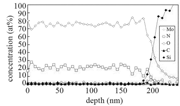 (b)
(b)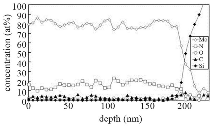 (c)
(c)
Figure 7. Mo, Si, N, C and O SNMS signals of molybdenum films heated at 673 K and exposed to (Ar-25%N2-30%H2) plasma for 15 min (a) and 40 min (b) at a distance of 9.5 cm from the centre of the discharge and exposed to (Ar-25% N2-30%H2) plasma for 15 min at a distance of 15.5 cm from the centre of the discharge (c).
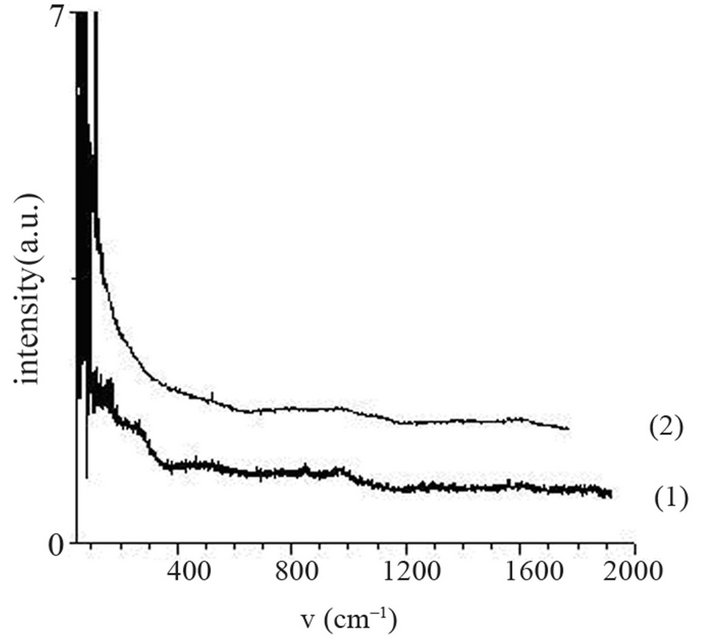
sity of electrons in (Ar-25% N2-30%H2) plasma is larger than the one corresponding to N2 plasma that results in an increase of the expansion of the plasma. The values are equal to 1016 and 0.16 × 10¹⁶ m–3 for (Ar-25%N2-30% H2) and N2 plasma, respectively [21]. They are equal to 1.5 × 10¹⁶ and 0.5 × 10¹⁶ m–3 at distances from the centre of the discharge equal to 10 and 11.5 cm, respectively for (Ar-8%N2-10%H2) plasma. Besides, these values are not much more different from the one corresponding to pure Ar which ranges between 0.5 and 1 × 10¹⁶ m–3. On the contrary, the density of electrons in (Ar-30%N2-12%H2) ternary plasma is lower and is nearly equal to the value found for pure N2 plasma i.e. 0.1 × 10¹⁶ m–3. So, no efficient nitriding process should be expected at distance of 15.5 cm from the center of the discharge since the plasma probably remains in a confined space around the center of the discharge like pure N2 plasma. Further investigations are needed to confirm this hypothesis. As we have previously seen in Table 1, the density of electrons in (Ar-25%N2-30%H2) and (Ar-8%N2-10%H2) gas mixtures remain high because the ionization thresholds corresponding to NH3, NH2 and NH are lower than those corresponding to Ar, N2 and H2. The SNMS results are confirmed by Raman spectroscopy which highlights the influence of hydrogen species on the transfer of nitrogen into the molybdenum films by reducing the oxide species. In contrast with the molybdenum films exposed to pure N2 plasma, the Raman spectrum corresponding to the molybdenum films exposed to (Ar-25%N2-30%H2) at 673 K for 15 min at a distance of 9.5 cm from the center of the discharge, does not display any features corresponding to MoO2 oxides. Only MoO3 oxides are still detected (Figure 8(a1)). So, hydrogen species in the plasma are efficient to reduce oxides which are formed in the film layers during treatment in the plasma. Since these oxides act as a barrier of diffusion, the hydrogen species improve the nitrogen transfer into the molybdenum films. It is worth noting that the most steady molybdenum oxide, MoO3 is not reduced by hydrogen species at 673 K; the heat of formation of MoO2 and MoO3 nitrides are equal to –544 and –755 kJmol–1, respectively whereas the heat of formation of molybdenum nitrides are lower and equal to –35 kJmol–1 at room temperature [50]. The large band identified at 300 cm–1, and assigned to Mo-N compounds containing defects appears more clearly as a hump at low wavenumbers. This can be correlated to X-ray results: the molybdenum films would consist of peaks corresponding to a mixture of Mo-N compounds containing defects and pure molybdenum [51]. Further investigations on films of larger thickness could confirm this hypothesis. These results are compared with those which have been obtained at higher temperature. The Raman spectrum of the molybdenum film heated at 873 K and exposed to (Ar-25%N2-30%H2) plasma at 12.5 cm from the center of the discharge is displayed on Figure 8(a2). The treatment leads to a nearly full reduction of all oxides remaining in the molybdenum film. Moreover the features detected at about 300 cm–1 have also disappeared. It is worth noting that the stoichiometric Mo2N compound of tetragonal structure has been identified in previous works conducted at 873 K [21]. The coefficient of diffusion of nitrogen in molybdenum films ranges between 5 × 10⁻¹⁰ to 5 × 10⁻⁹ cm2·s–1 at 873 K. According to the selection rules, a first-order Raman spectrum should appear and we did not find any spectrum corresponding to that structure in the literature. The morphology of films of molybdenum heated at 673 K and exposed to (Ar-8%N2-10%H2) for 15 min at 9.5 cm of the discharge is displayed on Figure 8(b). The surface consists of grains ranging in size from 50 to 100 nm. The morphology is quite similar to those obtained after exposing the film to (Ar-25%N2-30%
 (a)
(a)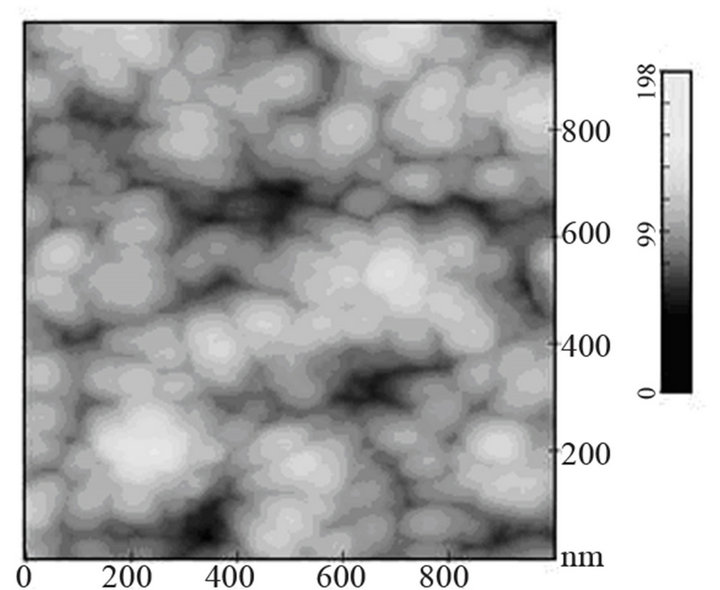 (b)
(b)
Figure 8. Raman scattering spectra of molybdenum film heated at 673 K (a1) and 873 K (a2) and exposed to (Ar- 25%N2-30%H2) plasma for 15 min and morphology of molybdenum film heated at 673 K and exposed to (Ar-8%N2- 10%H2) plasma for 15 min.
H2) or pure N2 plasma. The nitriding treatment leads to a slight decrease of the grain size and a slight increase of the roughness, since it is equal to 15.8 nm.
6. Conclusion
The thermochemical process using expanding plasma of (Ar-N2-H2) mixtures improves the diffusion of nitrogen into thin films of molybdenum metal coated on Si substrates heated at low temperature. Such conditions of temperature prevent the substrate from damaging in case of glass substrates. (Ar-N2-H2) plasma contains hydrogen species which play a great role in the reducing of oxide compounds whose act as diffusion barriers for nitrogen. In contrast with nitriding treatments carried out in pure N2 plasma, molybdenum oxide such as MoO2 does not form in the metal film. Moreover, (Ar-25%N2-30%H2) and (Ar-8%N2-10%H2) ternary plasma produce a large amount of NHx species since ionization is more efficient at low electron energy for NHx species than for N2, H2 or Ar. NHx species are produced by homogeneous and heterogeneous reactions involving the wall of the reactor. Since the surface/volume ratio of our reactor is large, NH3 species are mainly produced on the wall of the reactor. In these two ternary plasma the density of electrons is larger than in pure N2 plasma, that allows the nitriding treatment to be performed on larger surface by carrying the active species far from the center of the discharge. Although the diffusion of nitrogen into the metal films has been fruitfully correlated to the formation of NHx species in plasma of (Ar-N2-H2), some questions remain open; in contrast to (Ar-25%N2-30%H2) and (Ar-8%N2-10%H2) ternary plasma, the density of electrons in (Ar-30%N2- 12%H2) gas mixture is nearly similar to that of pure N2, so, it probably remains in a confined space around the center of the discharge. Other investigations will be conducted. Moreover, the large Raman band recorded at small wavenumbers on the spectrum corresponding to molybdenum films heated at 673 K could be assigned to the formation of defects in the compounds of molybdenum nitride, this Raman feature could not readily correlated to the XRD results because of the low thickness of the metal films, so other investigations will be conducted on films of larger thickness to explore these phenomena a little further.
7. Acknowledgements
We would like to thank the Region Limousin for its financial support on surface reactivity.
REFERENCES
- M. Nagae, T. Yoshio, Y. Takemoto and J. Takada, “Microstructure of a Molybdenum Layer Formed by Nitriding Molybdenum Metal,” Journal of the American Ceramic Society, Vol. 84, No. 5, 2001, pp. 1175-1177.
- S. M. Aouadi, Y. Paudel, B. Luster, S. Stadler, P. Kohli, C. Muratore, C. Hager and A. A. Voevodin, “Adaptive Mo2N/MoS2/Ag Tribological Nanocomposite Coatings for Aerospace Applications,” Tribological Letters, Vol. 29, 2008, pp. 95-103.
- S. M. Aouadi, Y. Paudel, W. J. Simonson, Q. Ge, P. Kohli, C. Muratore and A. A. Voevodin, “Tribological Investigation of Adaptative Mo2N/MoS2/Ag Coatings with High Sulphur Contents,” Surface and Coatings Technology, Vol. 203, No. 10-11, 2009, pp. 1304-1309.
- S. Franssila, H. Kattelus and E. Nykänen, “Stress Control of Sputter-Deposited Mo-N Films for Micromechanical Applications,” Microelectronic Engineering, Vol. 60, No. 1, 2002, pp. 97-105. doi:10.1016/S0167-9317(01)00585-8
- J. F. Zhu, J. C. Guo, R. S. Zhai, X. Bao, X. Y. Zhang and S. Zhuang, “Preparation and Adsorption Properties of Mo2N Model Catalyst,” Applied Surface Science, Vol. 161, No. 1, 2000, pp. 86-93. doi:10.1016/S0169-4332(00)00128-8
- C. Shi, A. M. Zhu, X. F. Yang and C. T. Au, “On the Catalytic Nature of VN, Mo2N and W2N Nitrides for NO Reduction with Hydrogen,” Applied Catalysis A: General, Vol. 276, No. 1-2, 2004, pp. 223-230. doi:10.1016/j.apcata.2004.08.017
- M. Nagai, “Transition-Metal Nitrides for Hydrotreating Catalyst-Synthesis, Surface Properties, and Reactivities,” Applied Catalysis A: General, Vol. 322, 2007, pp. 178- 190.
- T. Shiota, T. Imamura and S. Hasuo, “Plasma Nitridation Process for Superconducting Nb Wiring to Improve Their Annealing Stability,” Journal of Applied Physics, Vol. 70, No. 11, 1991, pp. 6958-6965. doi:10.1063/1.349823
- R. Fix, R. G. Gordon and D. M. Hoffman, “Low-Temperature Atmospheric-Pressure Metal-Organic Chemical Vapour Deposition of Molybdenum Nitride Thin Films,” Thin Solid Films, Vol. 288, No. 1-2, 1996, pp. 116-119. doi:10.1016/S0040-6090(96)08867-0
- V. P. Anitha, S. Major, D. Chandrashekharam and M. Bhatnagar, “Deposition of Molybdenum Nitride Thin Films by r.f. Reactive Magnetron Sputtering,” Surface and Coatings Technology, Vol. 79, No. 1-3, 1996, pp. 50-54. doi:10.1016/0257-8972(95)02425-5
- S. X. Song, Y. Z. Liu, D. L. Mao, H. Q. Ling and M. Li, “Diffusion Barrier Performances of Thin Mo, Mo-N and Mo/Mo-N Films between Cu and Si,” Thin Solid Films, Vol. 476, No. 1, 2005, pp. 142-147. doi:10.1016/j.tsf.2004.09.046
- H. Jehn and P. Ettmayer, “The Molybdenum-Nitrogen Phase Diagram,” Journal of the Less-Common Metals, Vol. 58, No. 1, 1978, pp. 85-98. doi:10.1016/0022-5088(78)90073-5
- M. Maoujoud, M. Jardinier-Offergeld and F. Bouillon, “Synthesis and Characterization of Thin-Film Molybdenum Nitrides,” Applied Surface Science, Vol. 64, No. 2, 1993, pp. 81-89. doi:10.1016/0169-4332(93)90267-F
- Y. M. Wang and R. Y. Lin, “Amorphous Molybdenum Nitride Thin Films Prepared by Reactive Sputter Deposition,” Materials Science and Engineering B, Vol. 112, No. 1, 2004, pp. 42-49. doi:10.1016/j.mseb.2004.05.010
- S. Mändl, J. W. Gerlach, W. Assmann and B. Rauschenbach, “Phase Formation and Diffusion after Nitrogen PIII in Molybdenum,” Surface and Coatings Technology, Vol. 174-175, 2003, pp. 1238-1242. doi:10.1016/S0257-8972(03)00457-2
- S. Mändl, D. Manova, J. W. Gerlach, W. Assmann, H. Neumann and B. Rauschenbach, “High Temperature Nitrogen Plasma Immersion Ion Implantation into Molybdenum,” Surface and Coatings Technology, Vol. 180-181, 2004, pp. 362-366. doi:10.1016/j.surfcoat.2003.10.134
- S. Mändl, J. W. Gerlach and B. Rauschenbach, “Nitride Formation in Transition Metals during High Fluence- High Temperature Implantation,” Surface and Coatings Technology, Vol. 200, No. 1-4, 2005, pp. 584-588. doi:10.1016/j.surfcoat.2005.01.040
- I. Jauberteau, J. L. Jauberteau, M. Cahoreau and J. Aubreton, “Metal Carburizing and Nitriding in an Expanding Microwave Plasma: The Impinging Plasma Species Promote the Surface Reactivity,” In: J. Menon, Ed., Trends in Vacuum Science and Technology, Research Trends, Trivandrum, 2001, pp. 77-99.
- I. Jauberteau, M. J. Cinelli, M. Cahoreau, J. L. Jauberteau, and J. Aubreton, “Expanding Microwave Plasma for Steel Carburizing: Role of the Plasma Impinging Species on the Steel Surface Reactivity,” Journal of Vacuum and Science Technology A, Vol. 18, No. 1, 2000, pp. 108-114. doi:10.1116/1.582126
- L. Thomas, J. L. Jauberteau, J. Aubreton, A. Catherinot, A. R. De Souza and M. J. Cinelli, “Characterization of a Microwave Plasma Jet Containing Ar-CH4 Gas Mixture,” Applied Physics Letters, Vol. 64, No. 20, 1994, pp. 2643- 2645. doi:10.1063/1.111478
- I. Jauberteau, J. L. Jauberteau, P. Goudeau, B. Soulestin, M. Marteau, M. Cahoreau and J. Aubreton, “Investigations on a Nitriding Process of Molybdenum Thin Films Exposed to (Ar-N2-H2) Expanding Microwave Plasma,” Surface and Coatings Technology, Vol. 203, No. 9, 2009, pp. 1127-1132. doi:10.1016/j.surfcoat.2008.10.012
- J. M. Modak, “Haber Process for Ammonia Synthesis,” 2002. http://en.wikipedia.org/wiki/Haber_process
- K. S. Yim and M. Venugopalan, “Plasma Chemical Synthesis: I. Effect of Electrode Material on the Synthesis of Ammonia,” Plasma Chemistry and Plasma Processing, Vol. 3, No. 3, 1983, pp. 343-350. doi:10.1007/BF00564632
- M. Touvelle, J. L. Munoz Licea and M. Venugopalan, “Plasma Chemical Synthesis: II. Effect of Wall Surface on the Synthesis of Ammonia,” Plasma Chemistry and Plasma Processing, Vol. 7, No. 1, 1987, pp. 1101-1108. doi:10.1007/BF01016001
- H. Hiyooka and O. Matsumoto, “Reaction Scheme of Ammonia Synthesis in the ECR Plasmas,” Plasma Chemistry and Plasma Processing, Vol. 16, No. 4, 1996, pp. 547- 562. doi:10.1007/BF01447008
- H. Uyama, T. Nakamura, S. Tanaka and O. Matsumoto, “Catalytic Effect of Iron Wires on the Syntheses of Ammonia and Hydrazine in a Radio-Frequency Discharge,” Plasma Chemistry and Plasma Processing, Vol. 3, No. 1, 1993, pp. 117-131. doi:10.1007/BF01447174
- A. Ricard, B. F. Gordiets, M. J. Pinheiro, C. M. Ferrira, G. Baravian, J. Amorim, S. Bockel and H. Michel, “Diagnostic and Modelling of N2-H2 Discharges for Iron Nitriding,” European Physical Journal: Applied Physic, Vol. 4, No. 1, 1998, pp. 87-93. doi:10.1051/epjap:1998246
- B. Gordiets, C. M. Ferreira, M. J. Pinheiro and A. Ricard, “Self-Consistent Kinetic Model of Low-Pressure N2-H2 Flowing Discharges: I. Volume processes,” Plasma Source Science and Technolgy, Vol. 7, No. 3, 1998, pp. 363-378. doi:10.1088/0963-0252/7/3/015
- B. Gordiets, C. M. Ferreira, M. J. Pinheiro and A. Ricard, “Self-Consistent Kinetic Model of Low-Pressure N2-H2 Flowing Discharges: II. Surface Processes and Densities of N, H, NH3,” Plasma Source Science and Technolgy, Vol. 7, No. 3, 1998, pp. 379-388. doi:10.1088/0963-0252/7/3/016
- J. L. Jauberteau, I. Jauberteau and J. Aubreton, “NH3 and NHx<3 Radicals Synthesis Downstream a Microwave Discharge Sustained in an Ar-N2-H2 Gas Mixture. Study of Surface Reactive Processes and Determination of Rate Constants,” Journal of Physic D: Applied Physic, Vol. 35, 2002, pp. 665-674.
- S. Touimi, J. L. Jauberteau, I. Jauberteau and J. Aubreton, “Plasma Chemistry and Diagnostic in an Ar-N2-H2 Microwave Expanding Plasma Used for Nitriding Treatments,” Journal of Physic D: Applied Physic, Vol. 43, No. 20, 2010, Article ID: 205203. doi:10.1088/0022-3727/43/20/205203
- J. H. van Helden, W. Wagemans, G. Yagci, R. A. B. Zijlmans, D. C. Schram and R. Engeln, “Detailed Study of the Plasma-Activated Catalytic Generation of Ammonia in N2-H2 Plasmas,” Journal of Applied Physic, Vol. 101, No. 4, 2007, Article ID: 043305. doi:10.1063/1.2645828
- J. H. van Helden, P. J. van den Oever, W. M. M. Kessels, M. C. M. van de Sanden, D. C. Schram and R. Engeln, “Production Mechanisms of NH and NH2 Radicals in N2-H2 Plasmas,” Journal of Physical Chemistry, Vol. A 111, 2007, pp. 11460-11472. doi:10.1021/jp0727650
- K. J. Laidler, “Catalysis,” The Waverly Press Inc., Baltimore, 1954, p. 206
- C. I. Butoi, M. L. Steen, J. R. D. Peers and E. R. Fisher, “Mechanism and Energy Transfer for Surface Generation of NH2 during NH3 Plasma Processing of Metal and Polymer Substrates,” Journal of Physical Chemistry, Vol. B105, 2001, pp. 5957-5967.
- H. Nagai, S. Takashima, M. Hiramatsu, M. Hori and T. Goto, “Behavior of Atomic Radicals and Their Effects on Organic Low Dielectric Constant Film Etching in High Density N2/H2 and N2/NH3 Plasmas,” Journal of Applied Physic, Vol. 91, No. 5, 2002, pp. 2615-2621. doi:10.1063/1.1435825
- V. Tarnovsky, H. Deutsch and K. Becker, “Cross-Sections for the Electron Impact Ionizations of NDx (x=1-3),” International. Journal of Mass Spectrometry, Vol. 167- 168, 1997, pp. 69-78. doi:10.1016/S0168-1176(97)00033-5
- National Institute of Standards and Technology (NIST). http://physics.nist.gov/PhysRefData/Ionization.html
- D. Rapp and P. Englander-Golden, “Total Cross Sections for Ionization and Attachment in Gazes by Electron Impact. I. Positive Ionization,” Journal of Chemical Physics, Vol. 43, No. 5, 1965, pp. 1464-1479. doi:10.1063/1.1696957
- N. Stothard, R. Humpfer and H. H. Grotheer, “The Multichannel Reaction NH2+NH2 at Ambient Temperature and Low Pressure,” Chemical Physics Letters, Vol. 240, No. 5, 1995, pp. 474-480. doi:10.1016/0009-2614(95)00563-J
- S. X. Huang, T. S. Rufael and J. L. Gland, “Diimide Formation on the Ni(100) Surface,” Surface Science Letters, Vol. 290, No. 1-2, 1993, pp. L673-L676.
- L. O. Alemàn-Vàzquez, E. Torres-Garcia, J. R. Villagomez-Ibarra and J. L. Cano-Dominguez, “Effect of the Particle Size on the Activity of MoOxCy Catalysts for the Isomerization of Heptane,” Catalysis Letters, Vol. 100, No. 3-4, 2005, pp. 219-225. doi:10.1007/s10562-004-3459-0
- M. Dieterle, G. Weinberg and G. Mestl, “Raman Spectroscopy of Molybdenum Oxides. Part I. Structural Characterization of Oxygen Defects in MoO3-x by DR UV/VIS, Raman Spectroscopy and X-ray Diffraction,” Physical Chemistry Chemical Physics, Vol. 4, No. 5, 2002, pp. 812-821. doi:10.1039/b107012f
- A. Klisinska, A.-S. Mamede and E. M. Gaigneaux, “Effect of the Nature of the Precursor on the Morphology of MoO3 Thin Films Spin-Coated on Si (100),” Thin Solid Films, Vol. 516, No. 10, 2008, pp. 2904-2912. doi:10.1016/j.tsf.2007.05.063
- M. Dieterle and G. Mestl, “Raman Spectroscopy of Molybdenum Oxides. Part II. Resonance Raman Spectroscopic Characterization of the Molybdenum Oxides Mo4O11 and MoO2,” Physical Chemistry Chemical Physics, Vol. 4, No. 5, 2002, pp. 822-826. doi:10.1039/b107046k
- L. Kumari, Y.-R. Ma, C.-C. Tsai, Y.-W. Lin, S. Y. Wu, K.-W. Cheng and Y. Liou, “X-Ray Diffraction and Raman Scattering Studies on Large-Area Array and Nanobranched Structure of 1D MoO2 Nanorods,” Nanotechnology, Vol. 18, 2007, Article ID: 115717. doi:10.1088/0957-4484/18/11/115717
- I. Jauberteau, J. L. Jauberteau, M. Cahoreau and J. Aubreton, “Surface Reactivity of Moybdenum Thin Films Exposed to (Ar-N2-H2) Expanding Microwave Plasma at Low Temperature: Influence of the Addition of H2 Gas in the Plasma,” Journal of Physics D: Applied Physics, Vol. 38, No. 19, 2005, pp. 3654-3663. doi:10.1088/0022-3727/38/19/014
- C. P. Constable, J. Yarwood and W.-D. Münz, “Raman Microscopic Studies of PVD Hard Coatings,” Surface and Coatings Technology, Vol. 116-119, 1999, pp. 155- 159. doi:10.1016/S0257-8972(99)00072-9
- C. L. Bull, T. Kawashima, P. F. McMillan, D. Machon, O. Shebanova, D. Daisenberger, E. Soignard, E. TakayamaMuromachi and L. C. Chapon, “Crystal Structure and High-Pressure Properties of Mo2N Determined by Neutron Powder Diffraction and X-Ray Diffraction,” Journal of Solid state Chemistry, Vol. 179, 2006, pp. 1762-1767.
- R. H. Perry and D. W. Green, Eds., “Chemical Engineering Handbook,” 6th Edition, McGrow-Hill, New York, 1984.
- S. Touimi, I. Jauberteau, J. L. Jauberteau, S. Weber, A. Bessaudou, A. Passelergue and J. Aubreton, “Plasma and Material Surface Investigations in a Nitriding Process of Thin Molybdenum Films Using an Expanding (Ar-N2-H2) Plasma,” Physical and Chemical News, Vol. 62, 2011, pp. 01-09.