Engineering
Vol. 4 No. 1 (2012) , Article ID: 17095 , 6 pages DOI:10.4236/eng.2012.41004
Effect of Pressure on the Fracture of Compacted Argillaceous Particles
1ENIS, Sfax, Tunisia
2Sfax University, IPEIS, Sfax, Tunisia
Email: hatem.ksibi@ipeis.rnu.tn
Received May 27, 2011; revised July 1, 2011; accepted July 10, 2011
Keywords: Cold Compaction; Powder Technology; Fracture; Scraped Surface; Cracking Cone; Numerical Simulation
ABSTRACT
The compaction of granulated powder is a common forming process used in ceramic and pharmaceutical industries. Argillaceous particles are used as a model system to investigate granule failure during cold compaction. In this work both experimental and numerical investigations have been focused on the fracture in powder compacts. This includes studies of crack propagation and determination of operating conditions to avoid the green body fracture. In fact, axial compaction tests have been performed to determine material parameters for hardening. The numerical modelling is implemented using a finite element method based on the Van Mises criterion. Simulation examples are presented to demonstrate the ability of the model to compute the distribution of the relative stresses in porous media.
1. Introduction
Powder compaction is a production method commonly used in the manufacturing industry today such as those in the ceramic forming, pharmaceutical and detergent industries [1,2]. The granulated material is consolidated by the application of pressure. Artifacts of the granule structure often persist as pores and laminations after compaction, and may persist as defects in the sintered microstructure. Such defects can be detrimental to the properties of the final part called “green body”. The fracture and deformation behavior of particles under impact loading is important in many industrial processes. For example, impact comminution is widely used to modify the size distribution of a population of particles. On the other hand, unintentional attrition by impact can degrade particles, and the resulting fragments may cause serious problems elsewhere in the system. Thus, it is desirable to eliminate the granule structure as completely as possible during the compaction.
In cold uniaxial powder compaction, the powder is formed into a desired shape with rigid tools and a die. A critical property in the powder pressing process is the mechanical properties of the formed piece. Beyond a defect-free green body, the desired properties are high strength and a uniform density. The compression induces a tensile stress perpendicular to the compressed diameter. Understanding breakage in granulation could lead to a better control of product quality and improved manufacturing efficiency. In either case, it is important to understand the mechanisms of failure under impact conditions so that these attrition and comminution processes can be appropriately controlled.
The current paper investigates the compaction of argillaceous powders experimentally and numerically. As the goal is to identify the breaking of a compacted cylindrical piece and the formation of the “cracking cone” fracture, a series of experiments has been performed by varying the compaction pressure. In the first section a description of the experimental setup is given and work conditions are summarized in Table 1. Successive photographs of several samples are taken after compaction. By using optical microscope, we have studied the compaction pressure effect on the granule size of powders. The second part of this paper evokes the numerical modelling of the stress field by using the software Cosmos-
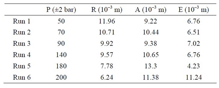
Table 1. Compaction pressure and measurements of the cracking cone of argillaceous powders at several experimental runs.
Works®. The powder compaction simulation process has been studied by several authors [3-5]. The industrial usability of these simulations to determine density gradients in compacted powder parts for different materials and shapes is limited by the knowledge of many parameters and the behaviour at high-pressure hydrostatic compression. In order to overcome this limitation, we need to determine the extent to which particular parameters affect the prediction by the model. The current numerical simulation of the die compaction process using finite element analysis provides a means to achieve this goal and the reliability of the fracture propagation to the pressure via a simple model using a continuum medium.
2. Experimental
2.1. Description of the Setup
Pressing in a practical situation is commonly done uniaxially. The powder is poured into the form by a powdershoe and a top punch moves downward applying a uniaxial pressure on the argillaceous particles. The mould is a cylinder with a steel disk-front and a back plate pressed into place in order to confine the powder in between. The dimensions of the mould are 30 × 10–3 m inner diameter and 60 × 10–3 m length. The pressing system has been designed with a run of instruments enabling to control the compaction process. Figure 1 shows the press setup with three main operations: the feeding with powder (A), the continuous compaction by displacing the top punch (B and C), and the ejection operation (D).
The necessary force to move the punch the desired distance is a function of the deformation mechanism of the material being compressed. Materials held under constant stress conditions may yield creep, hence additional punch movement, and therefore additional compaction work.
2.2. Operating Conditions
Firstly, the initial powder of clay was granulated, dried and sieved manually before pressing to obtain a calibrated powder size as shown in Figure 4. The average particle size of the formed aggregates is around 20 × 10–6 m. The pressure is varied by activating a hydraulic jack
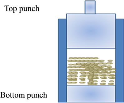
Figure 1. Description of the setup.
from 40 to 180 bars as given in Table 1. The compaction operation is stopped when the top punch comes to the butt detector fixed conveniently to the desired length of the argillaceous compacted die. After pressing, the detail is ejected and is now called a “green body”. The mechanical strength of the green body is enough to handle it after pressing but not enough to use it in practical situations with increasing loads. To enhance the mechanical behaviour in some cases, the powder particles need to be welded together using for example heat treatment as known in ceramics [6].
Although the ejection operation is carefully conducted, the formed green body is broken in every case. The fracture is always localised at the bottom of the formed piece. It is divided into two parts (a) and (b) as shown in Figure 2. The part (b) is called in few published works as the “cracking cone” [7,8]. It is characterised by several dimensions as mentioned in Figure 3. Table 1 summarizes the effect of the compaction pressure on these dimensions at each run where R is the radius, E the cone height, and A the distance between axis.
2.3. Experimental Results
2.3.1. Effect of Pressure upon the Ejection Operation
The experimental results show that dimensions of the
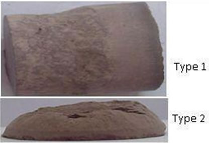
Figure 2. Fractures of the compacted powder after ejection.

Figure 3. Sketch of the cracking cone separated after compaction from the green body.
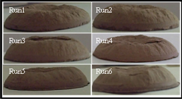
Figure 4. Different cracking cones at several experimental cases.
cracking cone (radius, height, angle…) depend on the compaction pressure level and also on the restructure of powders at each level of pressure. As a first remark, we notice that the forms of the cracking cone shown in Figure 4 are little altered by the pressure. Indeed, the propagation of the fracture at the bottom of the green body is performed uniformly for all compacted pieces. Optical measurements, however, show that dimensions vary enormously with the pressure level as it is the case for the radius (R) given in Table 1. Its fitting is well done (see Figure 5) via polynomial correlation which is given by the following equation: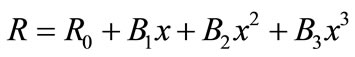 ,
,
where:
R0 = 19.484, B1 = –0.231, B2 = 1.87 × 10⁻³, B3 = –5.256 × 10⁻⁶.
We notice that the crack should be in the direction of the maximum shear stress intensity factor that is in the original crack plane or at a small angle from the original crack plane. In other words, the analysis proved that a more robust fracture criterion is needed to predict the occurrence of the crack. In literature, experimental and numerical simulation results on crack growth in compacted materials under compression indicate the same trend of crack propagation [11].
In fact, a crack can generally grow in different manners as the pressure varies. At a low pressure, it grows via incipient kink at an angle from the original crack plane. But under increasing pressure, it grows as a combination of open and shear crack. Finally, under substantially high pressure, the crack grows as a shear crack, straight ahead or at a small angle from the original crack plane.
2.3.2. Effect of Pressure upon the Ejection Operation
From Figure 6, we can notice that all the green body crusts are scraped to a given level which depends essentially on the pressure.
This is mainly due to the powder morphology and size (structure) and also the bonding and sliding of particles phenomena. Frictional forces at the die wall severely
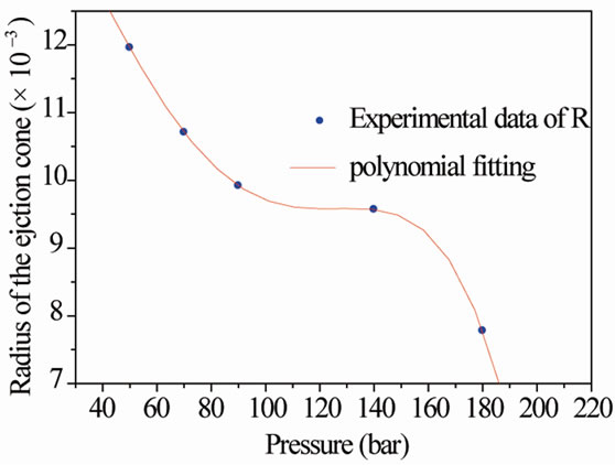
Figure 5. Numerical fitting of the “cracking cone” radiuses versus the hydrostatic pressure.
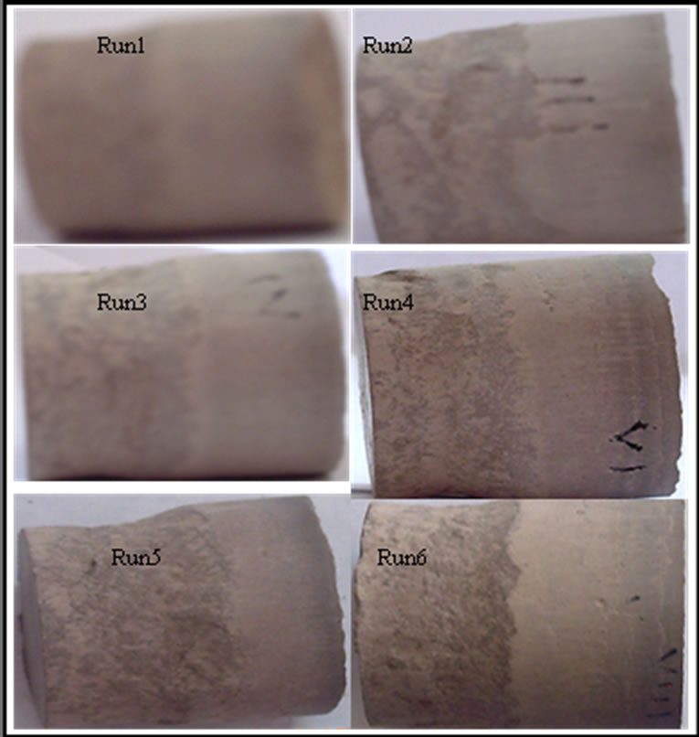
Figure 6. Photographs of the compacted pieces showing the scraped lateral crust level.
impede powder movement; this is seen as a force loss from the top to the bottom punch as was described by Ozkan and Briscoe [12].
As a result of these frictional effects, a pressure gradient is set up, which causes an uneven powder movement, Figure 6. Therefore, a heterogeneous density at the green body lateral edge is produced as well as an associated internal stress field. Towards the bottom of the green body, powder particles are experiencing less compressive force and hence lower densities.
3. Numerical Study
3.1. Background
To simulate densification behaviour in powder-forming processes, the finite element methods have been formulated by several research groups. Finite element methods (FEM) have been widely used for modelling the compaction of metallic and ceramic powders [13], and have recently been used for analysing pharmaceutical powder compaction [14].
Basically, there are two approaches, based on “porous” and “granular” material models, which have been developed to describe the effect of the stress state on the response of the powder material. These methods have been limited to the compaction of powder and the working of sintered metals where the densification behaviour caused by the action of external force is formulated. The compact and sintered piece undergoes a change in apparent volume resulting from the reduction of the pores during the forming (the time step). Since the inclusion of deformation behaviour of huge individual pores in the numerical simulation is not realistic in the present power of computers, the volume change is dealt with within the framework of continuum mechanics. The compact medium is modelled as porous materials obeying the macroscopic constitutive equations allowing for the volume change during the forming.
3.2. The Elastic Model
As a first approximation, the compacted powder behavior, in this work, is considered elastic with the hypothesis of small displacements and rotations. We apply the standard finite element Galerkin discretisation process to the standard displacement formulation with independent approximation of displacement (the isoparametric concept). This simple model is developed with respect to the Hooke law. The discritisation via finite element method of the virtual work displacement includes inertial, soliciting, and cushioning forces.
One of the most important material parameters that affects powder yielding under hydrostatic and shear stresses is the Young’s modulus. This can be simply determined by means of powder compaction experiments and by establishing the stress-strain curves at different levels of density. In this simulation, the Young’s modulus is set at a low value when we consider the compacted powder as a soft material medium.
3.3. Simulation Results
The given runs in Table 1 have been simulated using the software CosmosWorks®. When the convergence criterion is satisfied, we plot isovalues of Von Mises constraints at each numerical case. From these simulations we note the existence of three different zones: a high density zone in the bottom half is usually of a slightly higher density than the top corners; recalling that this is a single ended compaction. The compressive forces that are acting on the powder particles, within the powder bed, are accommodated by an increase in local stress which may allow us to show that they acted towards the bottom half of the formed pieces. This would cause the formation of high density region together with stress relief within the part of the green body adjacent to the moving top punch. Low density regions are also present in the “bottom corners” of the green body. Finally, the cracking cone is generally separated from the green body.
Generally, during compaction and ejection, residual stresses can be generated in the green body. The failure of a component is not only due to the external loading. A residual stress field might influence the sintering process and induce dimensional distortions and variations in mechanical properties within the final component, which might cause failure.
Isovalues show that any increase in pressure of compaction involves an intensive stress field in the middle of the green body and therefore the formation of a compacted hard-core (Figure 7). We notice that all isovalues are depicted using the same colour range. Thus, at low pressure, the green body is consolidated uniformly with a minor risk of crack. At its lateral surface, precisely in the bottom part, we notice that the propagation of crack and the formed crust will be scraped easily.
3.4. Validation
The separation or fragmentation of a solid body into two or more parts, under the action of stress, is a common definition of fracture, which is a result of crack initiation and propagation. The manufacturing of a green compact can vary from part to part depending on shape etc., although most compacts are pre-produced in several process stages. Cracks can be formed or initiated at any point during the pressing process, but are primarily formed during the compaction, ejection, and handling operations prior to sintering. According to Zenger and Cai [15], cracks in powder compacts during pressing can be classified when the inter-particle bonds are broken and/or the inter-particle bonds are not formed during compaction. The main cause of broken inter-particle bonds is the pulling apart of powder particles which have been locked together during compaction. This process is caused by tensile forces, lateral shear forces, or a combination of both.
When powder is compacted, the inter-particle bonds can break as the trapped air tries to escape under pressure. Insufficient vertical powder transfer in a levelled tool is another source of cracks as regions of partly compacted powder have to move relatively towards each other, caus-
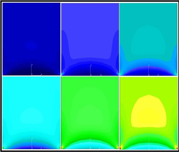
Figure 7. Isovalues of stress at different experimental conditions.
ing shearing zones.
To compare the simulation results with experimental measurements, a verification of the crack cone shape has been performed. The Von Mises constraint field is determined by computer simulation using CosmosWorks software. Figure 8 shows the obtained isovalues of a horizontal section through the pressed green body in run 1 seal together with the crack cone obtained experimentally. The dashed contour lines (in red) are very similar in the two pictures. There are several potential explanations for the slight differences in the absolute values on these plots. We underline that experimental measurements could lead to systematic deviations. Also, numerical calculation are done using hypothesis, mainly the continuum material medium. Therefore experiments with different calculations are in good agreement.
As a second verification, the lateral scraped level of the green body is measured. Figure 6 shows photographs of different obtained crusts and Figure 8 the deviations from a linear fitting for both the measured and the simulated values. The agreement is satisfactory and the differences between measured and calculated levels cannot necessarily be attributed to inaccuracies in the model, since the reference frame in the experiments is not wellcontrolled (Figure 9).
4. Conclusions
This work has been performed to investigate residual stress development, tensile fracture and mechanical properties of powder compacts. We fabricated argillaceous green bodies using a compaction process and simulated their stress fields in the same conditions. The comparison
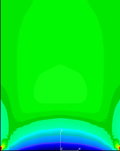
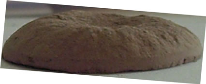
Figure 8. Comparison between constraint isovalues of a horizontal section through the pressed green body and the obtained crack cone.
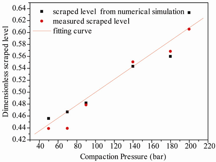
Figure 9. Comparison between measurement and numerical values of the level.
of simulation and experimental results confirmed the accuracy of the model.
Compacting pressure, upper punch hold down and die taper geometry have a significant influence on the residual stress state while die wall friction has a small influence. We conclude that the ejection part of the pressing cycle or more precisely the process of the powder compact release from the die is the main reason for high residual stresses.
The application using the finite element simulation method is a possible optimization of the compressing process. It can predict the generated part of cracks and there is a possibility of getting a faster and more accurate result than the existing experiment method. Although at the moment, the model assumes a simple linear constitutive law for the filled cells and linear interpolation functions for the displacement field, the obtained results are very promising.
5. Acknowledgements
Authors thank Professor M. Affes for his English assistance in the preparation of this manuscript.
REFERENCES
- M. A. Meyers, A. Mishra and D. J. Benson, “Mechanical Properties of Nanocrystalline Materials,” Progress in Materials Science, Vol. 51, No. 4, 2006, pp. 427-556. doi:10.1016/j.pmatsci.2005.08.003
- S. C. Lee and K. T. Kim, “A Study on the Cap Model for Metal and Ceramic Powder under Cold Compaction,” Materials Science and Engineering A, Vol. 445-446, 2007, pp. 163-169. doi:10.1016/j.msea.2006.09.013
- K. Mori, “Finite Element Simulation of Powder Forming and Sintering,” Computer Methods in Applied Mechanics and Engineering, Vol. 195, No. 48-49, 2006, pp. 6737- 6749. doi:10.1016/j.cma.2005.10.015
- P. Jonsén and H. Häggblad, “Modelling and Numerical Investigation of the Residual Stress State in a Green Metal Powder Body,” Powder Technology, Vol. 155, No. 3, 2005, pp. 196-208. doi:10.1016/j.powtec.2005.05.056
- Y. S. Kwon, S. H. Chung, H. I. Sanderow, K. T. Kim and R. M. German, “Numerical Analysis and Optimization of Die Compaction Process,” PM2TECH Conference, Las Vegas, 2003, pp. 4-37.
- M. Miyashita, J.-Y. Kim, Z. Kato, N. Uchida and K. Uematsu, “Effect of Compaction Pressure on the Internal Structure of Sintered Alumina,” Journal of the Ceramic Society of Japan, Vol. 17, No. 2-3, 1997, pp. 177-181.
- A. D. Salman, G. K. Reynolds, J. S. Fu, Y. S. Cheong, C. A. Biggs, M. J. Adams, D. A. Gorham, J. Lukenics and M. J. Hounslow, “Descriptive Classification of the Impact Failure Modes of Spherical Particles,” Powder Technology, Vol. 143-144, 2004, pp. 19-30. doi:10.1016/j.powtec.2004.04.005
- S. Abid, M. Bouaziz and H. Ksibi, “Cracking Cone Fracture Afterwards Cold Compaction of Argillaceous Particles,” Bulletin of Materials Science, Vol. 32, No. 6, 2009, pp. 607-610. doi:10.1007/s12034-009-0093-x
- J. X. Liu and T. J. Davies, “Coordination NumberDensity Relationships for Random Packing of Spherical Powders,” Powder Metallurgy, Vol. 40, No. 1, 1997, pp. 48-50.
- J. X. Liu and D. P. De Lo, “Particle Rearrangement during Powder Compaction,” Metallurgical and Materials Transactions A, Vol. 32, No. 12, 2001, pp. 3117-3124. doi:10.1007/s11661-001-0186-7