Engineering
Vol. 3 No. 2 (2011) , Article ID: 4284 , 4 pages DOI:10.4236/eng.2011.32015
Shallow Axi-symmetric Bimetallic Shell as a Switching Element in a Non-Homogenous Temperature Field
Faculty of Maritime Studies and Transport, University of Ljubljana, Portorož, Slovenia
E-mail: marko.jakomin@fpp.uni-lj.si
Large Displacement Theory
Received December 26, 2010; revised January 4, 2011; accepted January 18, 2011
Keywords: Bimetallic Shell, Non-Homogenous Temperature Field, Snap-Through of the System,
ABSTRACT
In this contribution we discuss the stability of thin, axi-symmetric, shallow bimetallic shells in a non-homogeneous temperature field. The presented model with a mathematical description of the geometry of the system, displacements, stresses and thermoelastic deformations on the shell, is based on the theory of the third order, which takes into account not only the equilibrium of forces on a deformed body but also the non-linear terms of the strain tensor. The equations are based on the large displacements theory. As an example, we present the results for a bimetallic shell of parabolic shape, which has a temperature point load at the apex. We translated the boundary-value problem with the shooting method into saving the initial-value problem. We calculate the snap-through of the system numerically by the Runge-Kutta fourth order method.
1. Introduction
A bimetallic shell is a heat sensitive construction element that changes its geometry under temperature load. The Austrian manufacturer of bimetallic shells, Elektronik Werkstatte from Vienna offers on the market some differrent types of thin shallow axi-symmetric bimetallic shells, Figure 1. In practice, rotational axi-symmetric bimetallic shells of spherical shape are the most common.
At the initial stage, such a shell responds to a temperature load T by changing the flexion curvature  while at a given temperature Tp it passes from a stable equilibrium position into a labile one, due to which the shell snaps-through into a new stable equilibrium position. This phenomenon is known in literature under the term ‘snap-through of the system’. The temperature Tp at which the shell snaps-through into a new equilibrium position depends on the material and geometric properties of the shell, and the method of temperature loading. Shells in a homogenous temperature field are the most studied [1-10]. With this supposition, at any given moment, each part of the shell has the same temperature
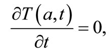
 , making the heat flow in the shell equal to zero:
 (1)
(1)
However, the homogeneous temperature field can only be presumed when the thin shell is heated very slowly and equally across its surface. In the case of fast and spatially varying temperature changes, a mathematical model that can acceptably explain the mechanical and stability characteristics of the temperature loaded shell can no longer be created with this supposition. Hence, in this contribution we will discuss a thin, axi-symmetric, shallow bimetallic shell, which has a constant temperature load  at the apex. This type of temperature load that adheres to the apex of the shell can be caused by contact

Figure 1. Some of the different types of bimetallic shells.
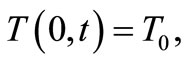
between the heated part of the device and the shell acting as a heat switch. Because of the thinness of the shell, we will assume that the temperature T across the shell crosssection r is constant at the time t:
 (2)
(2)
In addition, we will ignore the heat flow  between the shell and its surroundings. We will therefore consider that the shell is perfectly insulated, due to which the heat flow will only be present in the shell, running from the apex to the edge for as long as there is a temperature difference in parts of the shell.
2. Geometry of the Shell and Kinematic Equations
Figure 2 shows the rotational curvature  for the delineated middle surface of the thin-walled axi-symmetric shallow shell in the initial undeformed state. The shell deforms because of the effects of the temperature load. The point P on the undeformed shell displaces into the point
  on the deformed shell. Since the shell is of an axi-symmetric shape and under a temperature load at the apex, the displacement of the point P into the point
  is determined with the displacement vector
 , which in this case we write with the vector
  in the tangential direction and vector
  in the normal direction on the rotational curvature, Figure 2:
 (3)
(3)
In the Equation (3), the unit vectors in the tangential and normal directions on the rotational curvature  are marked with
  and
and , Figure 2. The rotational curve of the deformed shell is determined by the function
 . The position of point
  on the deformed shell is determined with the coordinates
 , Figure 2:
 (4)
(4)
 (5)
(5)
The discussed bimetallic shell is shallow, so the derivative of the rotational curvature with respect to the variable x is small:
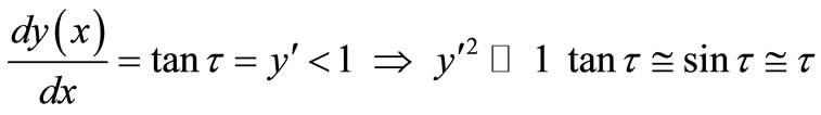 (6)
(6)
Strains occurring in the shell due to external loads must not exceed the material elastic limit, therefore, in the formation of a mathematical model we are allowed to introduce the supposition that all strains in the shell are, by absolute value, much smaller than the number one [4]:
 (7)
(7)
If we consider that the rotations of the shell elements are moderate up to approximately 20 degrees [11]:
 (8)
(8)
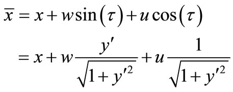
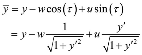
We can under the suppositions (6), (7), and (8) simplify the Equations (4) and (5), that determine the coordinates  of point
  on the deformed shell:
 (9)
(9)
 (10)
(10)
With the known equation from differential geometry we also write the length  of the elementary part of the undeformed shell on the rotational curvature:
 (11)
(11)
The length  of the elementary part of the shell we write with the displacements
  and
and  [12, 13], Figure 3:
 (12)
(12)
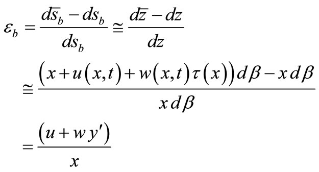
The strain of the shell element in the tangential direction is:
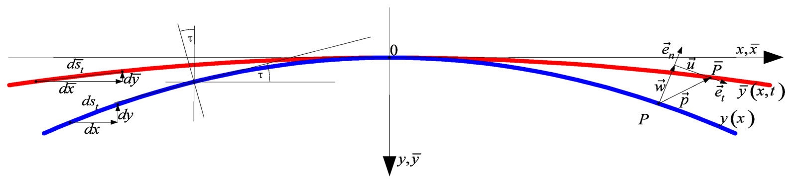
Figure 2. Displacements on an axi-symmetric shell due to the tempera-ture load at the apex of the shell.
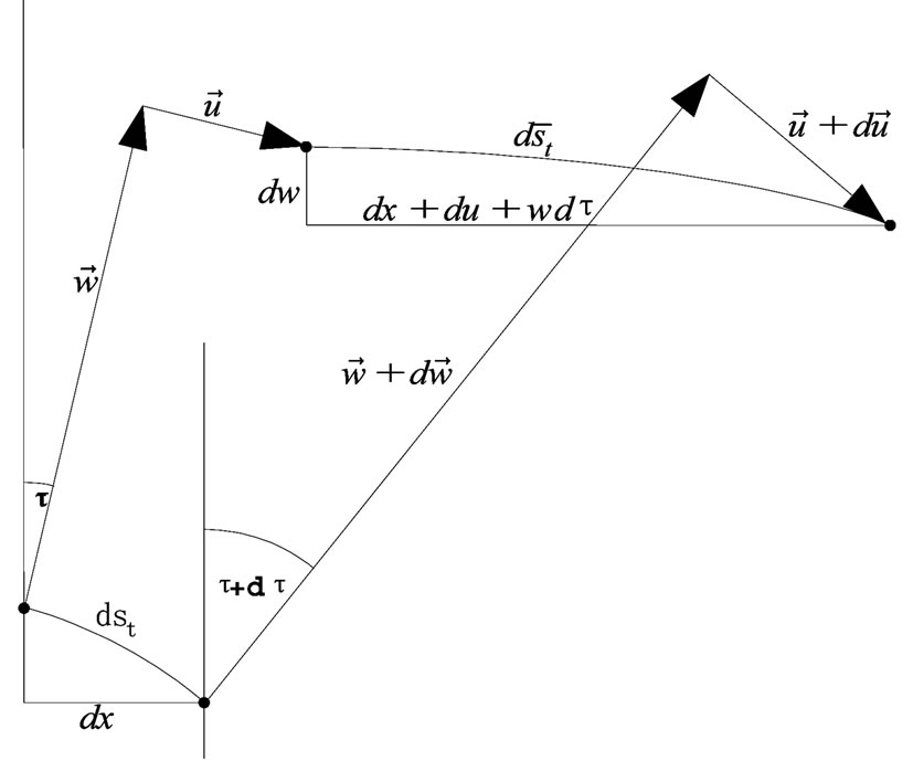
Figure 3. Deriving the equation for the strain  in the tangential direc-tion.
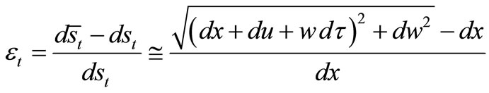 (13)
(13)
After we develop the Equation (13) into Taylor series and ignore the small nonlinear terms, the equation is:
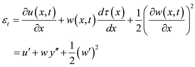 (14)
(14)
Since we are discussing a thin double-layered shell, the displacement field is selected to satisfy the Kirchhoff hypothesis [11]:
1) Strait lines perpendicular to the shell’s middle surface before deformation, remain straight after deformation;
2) The transverse normals do not experience elongation;
3) The transverse normals rotate, so that they remain perpendicular to the shell’s middle surface after deformation.
From Figure 4 it is clear that the displacement u is dependent on the local coordinate r, which is measured from the middle surface of the bimetallic shell in the direction of the unit vector :
:
 (15)
(15)
The strain  outside the middle surface of the shallow thin-walled bimetallic shell will thus, according to Equation (14), be:
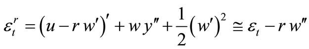 (16)
(16)
We determine the strain in the binormal direction on the rotational curvature  with Figure 5.
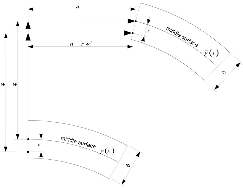
Figure 4. Displacement u at the distance r from the middle surface of the bimetallic shell.
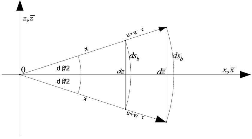
Figure 5. Deriving the equation for the strain  in the binormal direction.
 (17)
(17)
Outside the middle surface, at a distance r in the direction of the unit vector , this strain, after we consider the Equation (15) for the displacement u, Figure 4, will be:
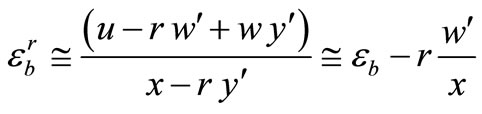 (18)
(18)
3. Equilibrium Equations
Figure 6 shows the cross-section of the elementary part of the deformed shell.
Due to the temperature load, internal forces and moments occur in the shell. In the cross-section that is orthogonal with respect to the rotational curve , the normal
  and shear
  forces and the bendingmoment
  act, while the normal force
  and the bending moment
  act in the lateral side of the shell element:
 , (19)
 (20)
(20)
 (21)
(21)
 (22)
(22)
 (23)
(23)
Where  and
and  are forces per unit of length, while
  and
and  are moments per unit of length in the case of thin-walled shallow shells. Stresses in the shell are denoted by
 and
and  The relation between stresses and strains is determined by Hooke’s law [12]:
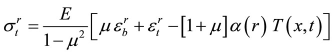 (24)
(24)
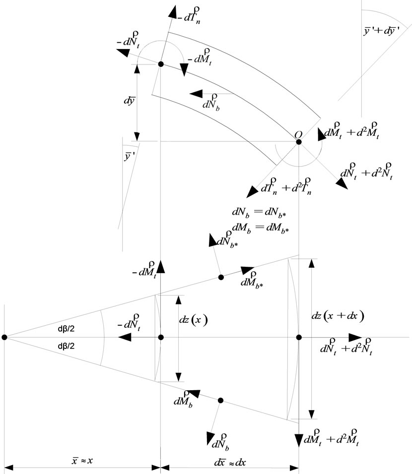
Figure 6. Forces and moments per unit of length acting in the element of a deformed shell.
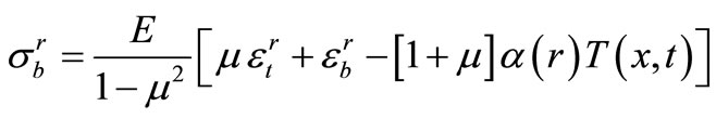 (25)
(25)
In the equations for stresses (24) and (25), function  denotes the temperature relative to the so-called reference temperature
  where the stress state throughout the undeformed shell equals to zero:
 .
.
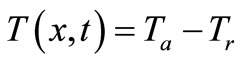
Therefore, the temperature  in Hooke's law equations is the difference between the actual temperature
  and the reference temperature
  at which the shell is without stresses:
 (26)
(26)
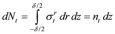
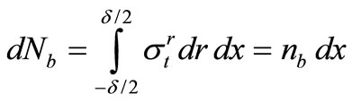
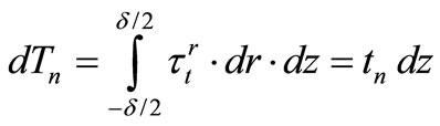
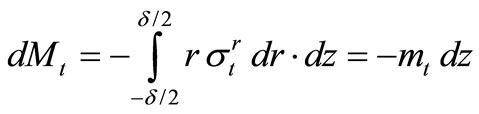
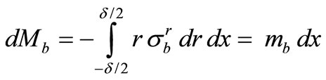
With this, the given integrals (19), (20), (21), (22) and (23) are:
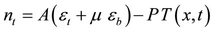 (27)
(27)
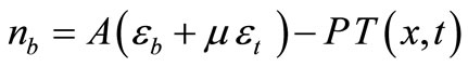 (28)
(28)
 (29)
(29)
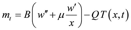 (30)
(30)
where ,
,  ,
,  and
and  are constants:
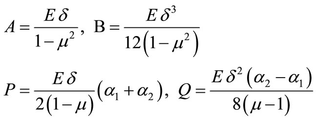 (31)
(31)
Now we can write the equation for the equilibrium of forces acting in the shell element in the tangential direction at point , Figure 6:
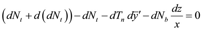 (32)
(32)
and similarly in the normal direction, Figure 6:
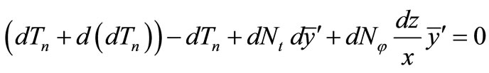 (33)
(33)
Due to the axi-symmetric stress and strains state the equilibrium equation in the binormal direction is identically equal to zero. Let us also write the equation for the equilibrium of moments around the point , Figure 6:
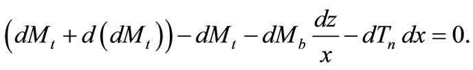 (34)
(34)
Let us consider that the differentials of unit forces and moments are:
 ,
,
 ,
,
and the equilibrium Equations (32), (33) and (34) after arranging:
 (35)
(35)
 , (36)
 . (37)
The shear force per unit of length  can be expressed from equilibrium equations. For this purpose we multiply the Equation (35) with
  and add the Equation (36):
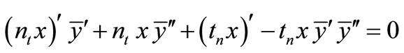 .
.
We can ignore the last term in the equation above as according to the supposition (6):
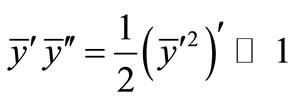 .
.
With this, after arranging we obtain:
and after integrating:
 (38)
(38)
We replace the shear force tn in the equilibrium Equations (35) and (36) with the Equation (38), and the other forces and moments nt, nb, mt, and mb with the Equations (27)-(30). We replace the first and second derivative of the rotational curvature  with the first and second derivatives of the Equation (10):
 (39)
(39)
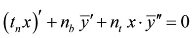
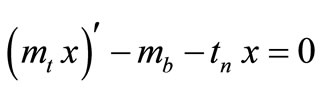
With this, the equilibrium Equations (35) and (36) pass into the final form:
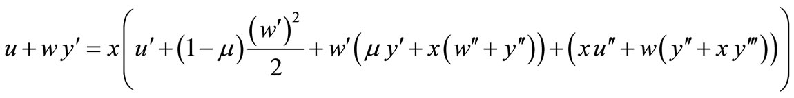 (40)
(40)
 (41)
(41)
The differential Equations (40) and (41) for determining the displacements  and
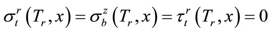
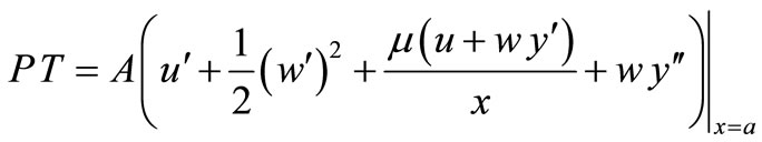
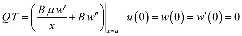
and  should be supplemented with the equations for boundary conditions. If the bimetallic shell is to serve as a thermal switch shutting down a device when it overheats, then it is necessary to assure that the shell can extend unrestrictedly in a horizontal direction [4,7]. So, in continuation, we will discuss a simply supported shell. At the boundary of the simply supported shell, the forces and moments per unit of length are equal to zero:
 (42)
(42)
We use Equations (27) and (29):
 (43)
(43)
 (44)
(44)
The displacement  at the apex of the shell is equal to zero in the chosen coordinate system:
 (45)
(45)
Furthermore the reader should note that the system of Equations (40), (41), (43) and (44) have a symmetry. If the displacement vector 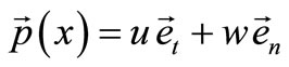 is the solution to this system, then the solution is also:
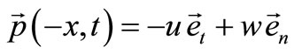 (46)
(46)
due to which, it is sufficient that we solve the system of equations only for the positive  values in the interval
 . For the negative
 , the displacement vector
  is defined by the Equation (46). The boundary conditions for the displacement vector
  also follow from Equation (46):
 (47)
(47)
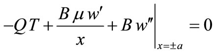
The remaining conditions at the edges of the shell at  are defined with the unit forces and moments in the equations for boundary conditions (43) and (44).
Therefore, the boundary-value problem for the snapthrough of the system of a shallow axi-symmetric bimetallic shell is composed of the equilibrium Equations (40), (41), and the boundary conditions (43) and (44) at the point , and the boundary conditions (47) at the point
 :
:

 (48)
(48)
We will calculate the temperature  of the shell in the boundary-value problem (BVP) (48) with the heat equation. Since the discussed shell is thin, we assume that the temperature
  after the shell cross-section
  at the time
  is constant (2). In addition, if we ignore the heat flow
  between the shell and its surroundings, we can write the net change of heat for the shell element in Figure 7:
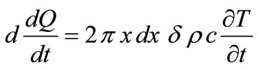 (49)
(49)
and the difference in heat flows on both edges of the shell:
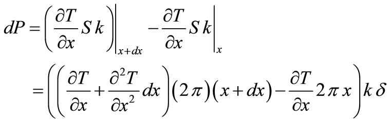 (50)
(50)
where ,
,  and
and  are material characteristic of the shell:
 : thermal capacity;
 : density;
 : thermal conductivity;
 : a cross-section of the of the shell element.
Since the net change of heat in the shell element is equal to the difference in the heat flow, then:
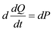 (51)
(51)
or after inserting the Equations (49) and (50), and arranging:
 (52)
(52)
We supplement the partial differential equation of the second order (52) with two boundary and one initial condition, so that the initial-boundary-value problem (IBVP) for determining the temperature state in the shell is:
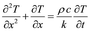
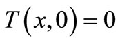
 (53)
(53)
4. Numerical Solution
We first translated the BVP (48) for the shell loaded at the apex with the temperature  into the system of five differential equations of the first order, in which the current shell temperature
  is determined by solution of the IBVP (53).
We solved this system of equations by first translating, with the non-linear shooting method, the solving of the boundary value problem into the solving of the initial value problem, which we then solved with the classic one-step Runge-Kutta 4th order method [14,15]. The parameter , represents the relation between the height of the deformed shell and the height of the undeformed shell:
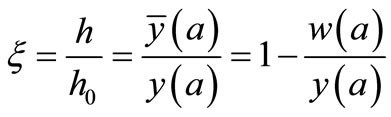 (54)
(54)
Therefore let us observe the stability conditions during the temperature loading of shells that have the following material and geometric characteristics:
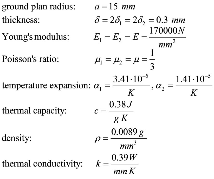 (55)
(55)

Figure 7. Heat flow in part of the shell cross-section with the mass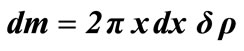 .
.
Figure 8 shows the process of heating the bimetallic shell with an initial height in the undeformed state . At the time
  we start to heat the shell at the apex with the constant temperature
 , Figure 8(a). Because of the temperature exerted at the apex of the shell, the temperature of the neighbouring points starts to rise while at the same time the shell deforms. Here, we observed that, at the start, the shell height h increases somewhat, and after a given time,
  in an actual example, the shell height starts to decrease. The relation of heights
  at which the shell becomes unstable is denoted by a black dot in Figure 9. At that moment the shell snaps-through into a new stable equilibrium position. The shape of the deformed shell and the temperature profile at the moment of the shell snap-through are shown in Figures 8(b) and 8(c). Figures 10-12, show these characteristics for shells with the initial height of
 ,
,  and
and .
.
We also estimated the error e of the described numerical procedure. For this purpose we calculated the shell heating time t when the current height h again becomes equal to the initial shell height . The results at different step size
  are written in Table 1. The difference between two successive results decreases each time for approximately one half. Thus, we can estimate the error
  of the numerical procedure with the equation:
 (56)
(56)
Therefore, the obtained results for the time t are correct to one decimal place even at a relatively large step size at  For estimating the error e, it is enough if we reduce the step
  by half and calculate a new, more accurate value. The difference with the previous result by the Equation (56) does approximately estimate the error e during calculation.
In Table 2, the reader can look for the maximal ratio  between the height h of the deformed, and the initial height
  of the undeformed shell, and the shell heating time t necessary for this deformation. The maximal height h at which a shell can deform is also evident in Figure 9 as the extreme of function
 .
.
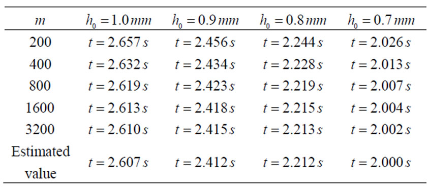
Table 1. Numerical results for the shell heating time  when ratio of heights
  becomes
  with different step size
 . Temperature
  at apex is
 .
.
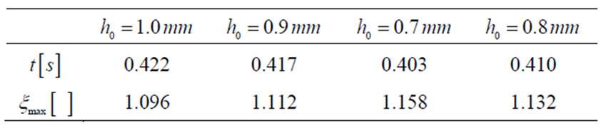
Table 2. The maximal ratio of heights  and the necessary heating time
  for shell of different initial heights at temperature load
  with
with .
.
The moment, at which the shell snaps-through into a new stable equilibrium position, is dependent on the material and geometric characteristics of the shell, as well as temperature load  at the apex of the shell. The values for time
  when the shell snaps-through into a new equilibrium position are written in Table 3. With the increase in the temperature load
 , the time
  needed for snap-through to occur is decreased. With the interpolation of results in Table 3 we approximately calculated the values for the snap-through time
  for the intermediate values of temperature loads. These results are graphically presented in Figure 13.
5. Conclusions
Simply supported thin-walled, shallow, bimetallic shells are distinguished by the property that at a given temperature they become unstable, the result of which is the snap-through of the shell from a convex into a concave shape, or vice versa, and the establishment once more of a stable equilibrium state. Due to this property, such shells are used for safeguarding various devices and machines from excessive temperature loads. With a suitable technical implementation, these shells can be connected to electrical contacts so that they cut-out at the moment when given parts of the safeguarded device overheat. Since the shell snap-through is a reliable, repeatable, and dynamic occurrence lasting around  thin-walled, shallow, bimetallic shells are very suitable for the thermal protection of devices, as apart from reliability, at snap-through they also prevent undesired and harmful sparking of electric contacts in the thermal switch. If the
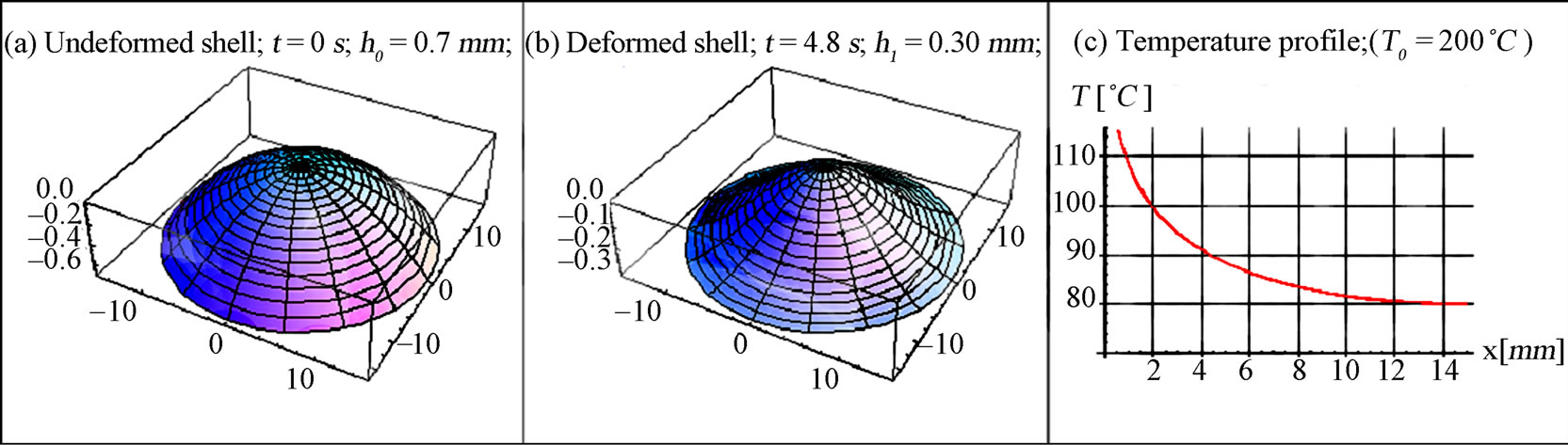
Figure 8. Shell shape with initial height  in a) an undeformed state, at b) the moment of snap-through, and c) the shell temperature at snap-through.
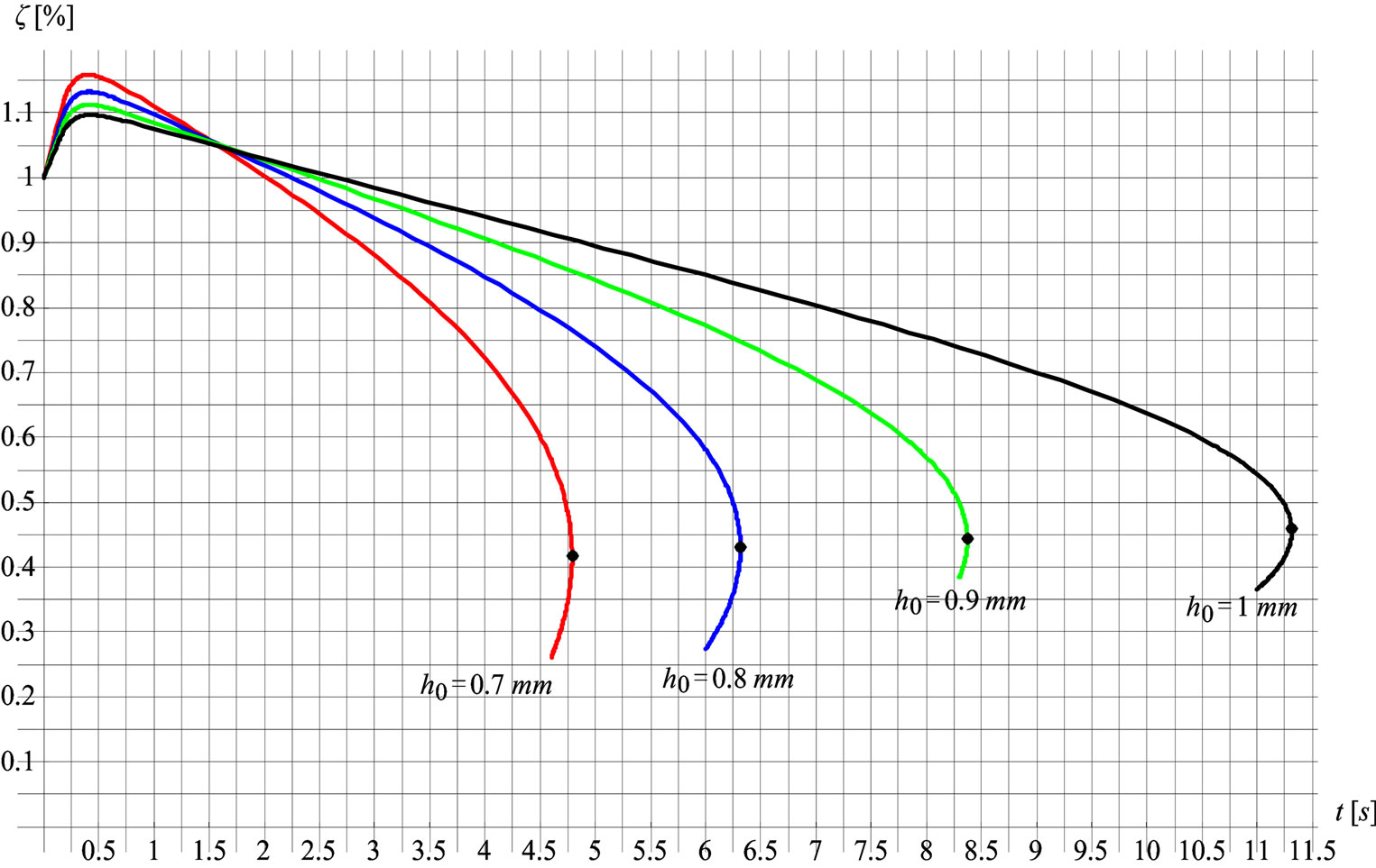
Figure 9. Ratio of heights  relative to heating time, at temperature load
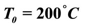 .
.
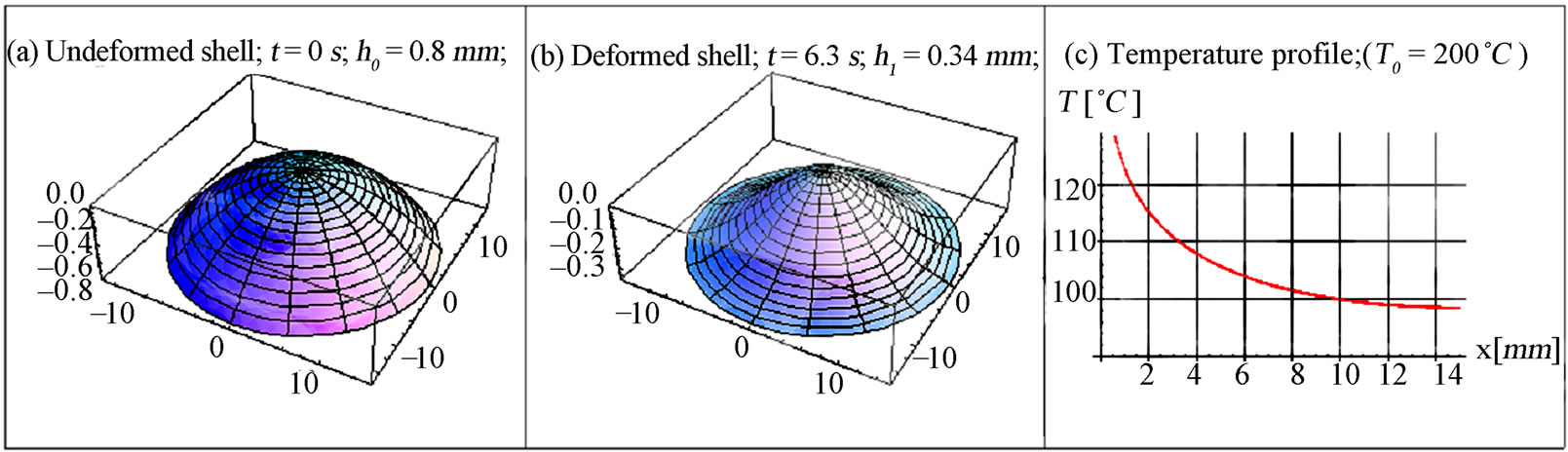
Figure 10. Shell shape with initial height  in a) an undeformed state, at b) the moment of snap-through, and c) the shell temperature at snap-through.
Figure 11. Shell shape with initial height 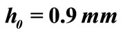 in a) an undeformed state, at b) the moment of snap-through, and c) the shell temperature at snap-through.
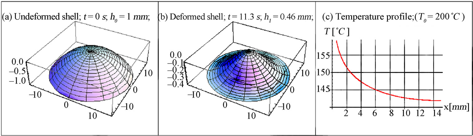
Figure 12. Shell shape with initial height 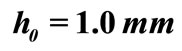 in a) an undeformed state, at b) the moment of snap-through, and c) the shell temperature at snap-through.
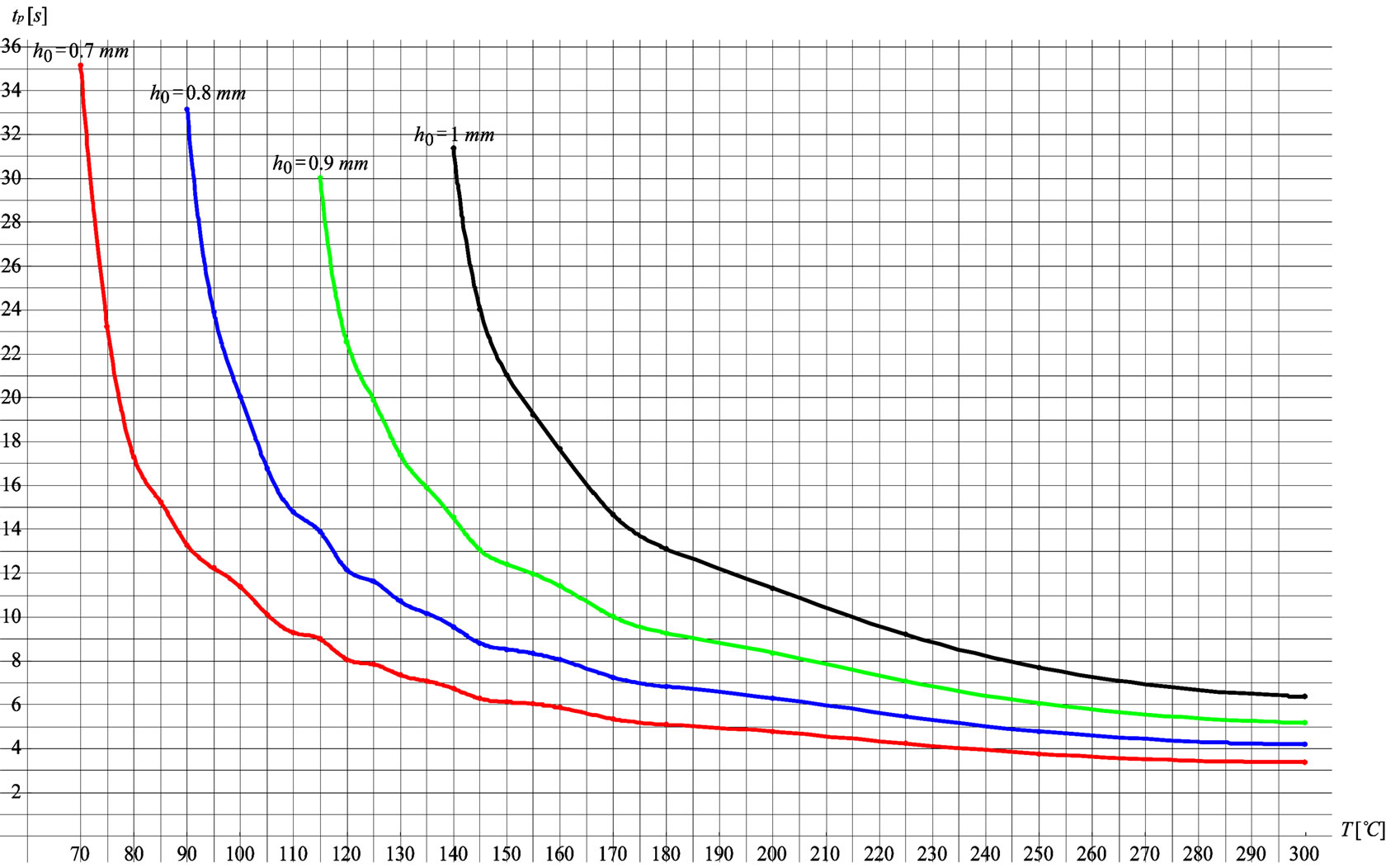
Figure 13. Heating time  for snap-through relative to temperature load
  and initial shell height
  with the interpolation of numeric results in Table 3.
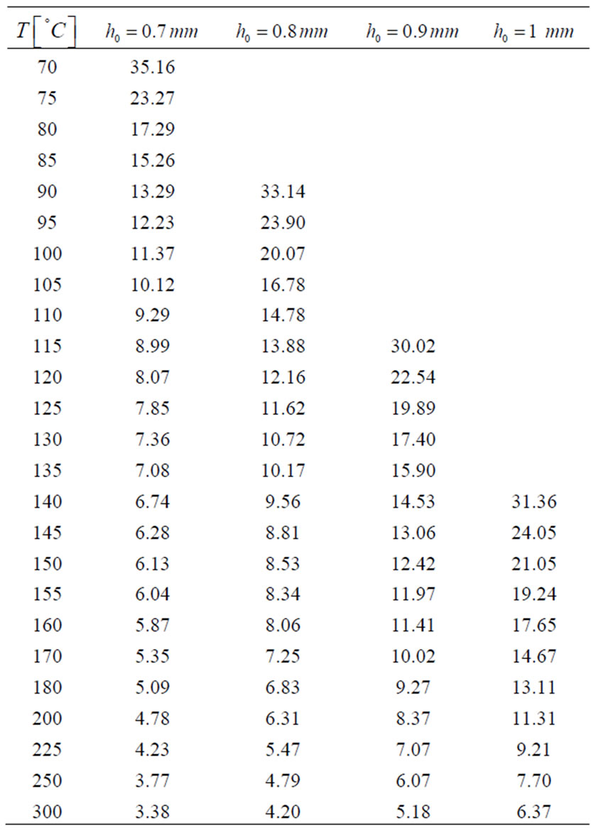
Table 3. Heating time  for snap-through relative to temperature load
  and initial shell height
 .
.
the safeguarded device, and with it the shell as a protective element, is heated slowly, we can legitimately assume that the shell is located in a homogenous temperature field. Therefore, such a temperature load case can be legitimately assumed only when the thin-walled shell is heated very slowly and equally across its surface. If the temperature changes are fast and irregular, we cannot presuppose a homogenous temperaure field. In this contribution, we discussed the problem of heating a thinwalled, shallow bimetallic shell at its apex. The consequence of the current temperature load at the apex of the shell is the increase in height  in the initial stage. Only after a given time, does this height start to decrease. The cause of this occurrence, not observed in shells in a homogenous temperature field, is that the area around the apex of the shell heats up very quickly with the temperature load, while the area at the edge of the shell remains cold. Due to this, the shell somewhat ‘swells up’ at the start, all the more the greater the temperature load
  at the apex of the shell. Within this lies the reason that the shell temperature at snap-through is at each point greater than the snap-through temperature
  of a shell with the same material and geometric characteristics in a homogenous temperature field.
When using these shells in practice, it is necessary to determine how the heating time  (enough for the shells to become unstable and snap-through) is relative to the material and geometric characteristics of the shell and the temperature load
  at its apex. The larger the temperature load
  is, the quicker does the shell snapthrough occur, and the lower is the initial height
  of the shell. Yet it is important to note, that very shallow bimetallic shells with a low initial height
  do not even have a snap-through. [9]. In the case of the shell with the characteristics (55), the critical value of the initial height
 , is
, is  when the snap-through of the shell is not possible anymore due to temperature loading. If the temperature load
  is equal to the snapthrough temperature
  of a shell located in homogenous temperature field, then theoretically, such a shell should be heated infinitely
 . On the other hand, the high temperature has as a result, a short time for the shell to snap-through. Apart from the temperature load
 , and the appropriate initial height
 , it is also necessary to ensure that the edge of the shell can expand unrestrictedly in a horizontal direction for the snapthrough of the shell to occur. Otherwise the shell cannot serve the function of a thermal switch.
6. REFERENCES
- W. H. Wittrick, W. H. Wittrick, D. M. Myers and W. R. Blunden, “Stability of a Bimetallic Disk,” The Quarterly Journal of Mechanics and Applied Mathematics, Vol. 6, No. 1, 1953, pp. 15-31. doi:10.1093/qjmam/6.1.15
- B. D. Aggarwala and E. Saibel, “Thermal Stability of Bimetallic Shallow Spherical Shells,” International Journal of Non-Linear Mechanics, Vol. 5, No. 1, 1970, pp. 49-62. doi:10.1016/0020-7462(70)90039-9
- L. R. Huai, “Non-Linear Thermal Stability of Bimetallic Shallow Shells of Revolution,” International Journal
- of Non-Linear Mechanics, Vol. 18, No. 5, 1983, pp. 409-429. doi:10.1016/0020-7462(83)90007-0
- F. Kosel, M. Jakomin, M. Batista and T. Kosel, “Snapthrough of the System of Open Axi-Symmetric Bimetallic Shell by Non-Linear Theory,” Thin-Walled Structures, Vol. 44, No. 2, 2006, pp. 170-183. doi:10.1016/j.tws. 2006.02.002
- M. Batista and F. Kosel, “Thermoelastic Stability of Bimetallic Shallow Shells of Revolution,” International Journal of Solids and Structures, Vol. 44, No. 2, 2007, pp. 447-464. doi:10.1016/j.ijsolstr.2006.04.032
- M. Jakomin, F. Kosel and T. Kosel, “Thin Double Curved Shallow Bimetallic Shell of Translation in a Homogenous Temperature Field by Non-Linear Theory,” Thin-Walled Structures, Vol. 48, No. 3, 2010, pp. 243-259. doi:10.1016/j.tws.2009.10.005
- M. Jakomin, F. Kosel and T. Kosel, “Buckling of a Shallow Rectangular Bimetallic Shell Subjected to Outer Loads and Temperature and Supported at Four Opposite Points,” Advances in Mechanical Engineering, Vol. 17, 2009, pp. 767648-1-767648-17.
- F. Kosel and M. Jakomin, “Snap-through of the AxiSymmetric Bimetallic Shell,” Proceedings of the Third International Conference on Structural Engineering, Mechanics and Computation, Cape Town, September 2007, pp. 348-356.
- F. Kosel and M. Jakomin, “Buckling of a Shallow Rectangular Bimetallic Shell Subjected to Outer Loads and Temperature,” Proceedings of SDSS Rio 2010, Rio De Janeiro, Vol. 2, September 2010, pp. 805-812.
- S. P. Timoshenko and J. M. Gere, “Theory of Elastic Stability,” McGraw-Hill, New York, 1961.
- J. N. Reddy, “Theory and Analysis of Elastic Plates,” Taylor & Francis, Philadelphia, 1999.
- N. A. Alfutov, “Stability of Elastic Structures,” Springer, New York, 1999.
- P. L. Gould, “Analysis of Plates and Shells,” Prentice Hall, New Jersey, 1999.
- D. J. Hoffman, “Numerical Methods for Engineers and Scientists,” McGraw-Hill, New York, 2001.
- M. H. Holmes “Introduction to Numerical Methods in Differential Equations,” Springer, New York, 2007. doi: 10.1007/978- 0-387-68121-4