Materials Sciences and Applications
Vol.05 No.11(2014), Article ID:50233,8 pages
10.4236/msa.2014.511080
Electromagnetic Waves Absorbing Characteristics of Composite Material Containing Carbonyl Iron Particles
Victor A. Zhuravlev, Valentin I. Suslyaev, Evgeny Yu. Korovin, Kyrill V. Dorozhkin
Department of Radioelectronics, National Research Tomsk State University, Tomsk, Russia
Email: ptica@mail.tsu.ru
Copyright © 2014 by authors and Scientific Research Publishing Inc.
This work is licensed under the Creative Commons Attribution International License (CC BY).
http://creativecommons.org/licenses/by/4.0/


Received 2 July 2014; revised 6 August 2014; accepted 3 September 2014
ABSTRACT
Results of measurements of permeability, permittivity and radar absorption properties of composites on basis of carbonyl iron particles R-10 brand are presented in this paper. The calculations and experimental studies have shown that in the super high frequency (SHF) and extremely high frequency (EHF) ranges on the basis of two-layer structures with different content of carbonyl iron particles can create a radar absorbing coatings with a reflectivity of less than −10 dB over a wide bandwidth from 3.1 to 17.1 GHz and from 27 to 37 GHz. Absorbing properties of composites are saved in terahertz frequency range from 250 to 525 GHz.
Keywords:
Electromagnetic Wave Absorbers, Radar Absorbing Materials and Coatings, Composite Materials, Carbonyl Iron Powders, Spectrum of Permittivity and Permeability

1. Introduction
Active development of the microwave frequency range sharpened the need for magnetic materials absorbing electromagnetic radiation. Such materials are required to reduce harmful influence on biological objects, to provide electromagnetic compatibility of units and blocks of high-frequency devices, to build anechoic chambers and to protect information. Composite radar absorbing coating (RAC) which consists of a matrix of high-mole- cular polymer compounds and filler particles of ferromagnetic or ferrimagnetic materials are widely used [1] . Such materials are most effectively used as electromagnetic waves absorbers (EMWA) located on the metal surfaces.
The carbonyl iron powders (CIP) are used at works [2] -[10] as fillers for composite RAC in microwave range. Investigation of complex permeability (μ = μ' − iμ") and permittivity (ε = ε' − iε") spectra of composites with different concentration of CIP at frequencies up to 18 GHz shows that these materials have noticeable permeability and permittivity loses, and they are perspective as EMWA for microwave frequency range. The rather narrow operating frequency band is disadvantage of such RAC.
It is shown in [5] [6] that double-layer RAC is more broadband and has less reflection coefficient than single- layer RAC [1] -[3] [7] -[10] . The first layer of such RAC is an absorbing layer. It is located on the metal surface. The second layer is matching with free space. It has smaller values of the permeability and permittivity.
It is known [11] that frequency band of high magnetic loses caused by natural ferromagnetic resonance at presence of domain structure lies generally in the limits from 2πf1 = γHa to 2πf2 = γ(Ha + 4πМS). Because of big value of saturation magnetization of iron MS ≈ 1.7 kGs the frequency band of high magnetic loses is from f1 ≈ 1.4 GHz up to f2 ≈ 61 GHz. In calculation it is accepted γ/2π = 2.8 GHz/kOe, anisotropy field Ha ≈ 0.5 kOe. This estimation shows that composite materials on basis of CIP can have noticeable absorbing properties in wide frequency range, including SHF and EHF.
Results of investigation of permittivity and permeability spectra, absorbing properties of composite materials composed of CIP of R-10 brand in polyurethane matrix are presented in this paper. CIP of R-10 brand had onion like structure with average size of particles about 3.5 µm. Thickness of investigated flat samples was 1 mm , volume content of CIP 9% (sample 1) and 53% (sample 2).
2. Theory
Theoretical analysis of radar absorbing properties of materials is usually carried out for the simplest case of normal incidence of a plane electromagnetic wave (EMW) on a magnetodielectric (MD) layer. Permeability (μ) and permittivity (e) of layer are taken as complex scalar quantities. For developing of radio protective materials and coatings located in free space layer of MD without metallization is considered. For reduction of radar signature a model of MD layer disposed on the metal surface is used. Formulas for calculating the complex reflection (RT) and transmission (TT) coefficients in the first case can be written in the form [12] :
 (1)
(1)
Here: —reflection coefficient from the front edge of MD.
 —wave impedance.
 —EMW propagation constant in MD.
 —the wave number of free space.
 —cir- cular frequency of the EMW. c—the speed of light. d—thickness of the layer.
 .
.
Expression for the reflection coefficient (RR) for located on the a metal plate layer of MD has the form [12] :
 . (2)
. (2)
Commercial advantage has RAC with a small thickness and weight. Therefore it is interesting to analyze the expression (1) and (2) in the case of a thin layer and find out which material parameters are crucial to improve the efficiency of consumer qualities of such materials. Use the approximation of a electrically thin layer: . In the linear approximation formulas (1) are significantly simplified and coefficients RT, TT can be rewritten as:
 (3)
(3)
For the modules of the transmission and reflection coefficients are obtained the following expressions:
 . (4)
. (4)
According to formulas (3), (4) in the thin layer approximation a module of the transmission coefficients depends only on the imaginary parts of permittivity and permeability describing the magnetic and dielectric losses in the MD layer. The reflection coefficient vanishes when real and imaginary parts of the permeability and permittivity are equal. In this case there is equality of the wave impedances of the interface MD layer and free space. In real composites to achieve such equality it is impossible.
The expression (2) for the module of reflection coefficient located on a metal surface layer of MD at  can be written:
 . (5)
. (5)
The reflection coefficient depends only on the imaginary part of permeability MD in this case. The optimal thickness of the layer (dopt) ensuring the absence of the reflected wave is equal to:
 (6)
(6)
Equation (6) contains an important consequence for practical applications. To ensure the broad band RAC the imaginary part of permittivity of MD should vary inversely proportional to the frequency:
 (7)
(7)
It should be noted that the formulas (4) and (5) provide an opportunity to solve another important experimental problem—to assess the values of the imaginary components ,
,  from the measured values of
  and
and .
.
Calculation of the reflection coefficient of multilayer RAC was carried out in [13] . The formula for the reflection coefficient from the interface between the n + 1 and n layers is follows:
 . (8)
. (8)
 —impedance of layer n + 1.
 —input impedance of layer n. It is equal to
 . (9)
. (9)
Equations (8) and (9) will be used later to calculate the reflection coefficient of the two-layer RAC located on the metal surface.
3. Results and Discussions
3.1. Permeability and Permittivity Spectra of Composite
Spectra of permeability (μ = μ' − iμ") and permittivity (ε = ε' − iε") measured using vector network analyzer Agilent Technologies E8363B. Measurements were performed in the frequency range 10 MHz - 20 GHz. A coaxial waveguide (R/T method, [12] ), an irregular microstrip resonator [14] [15] , and a set of rectangular multimode volume resonators [16] were used as measuring cells.
Since various experimental techniques have different systematic and random measurement errors, permeability and permittivity values measured by the corresponding methods at the ends of the examined frequency range differed. In this regard, the experimental magnetic spectra of the composites were processed by the method suggested in [17] [18] . To match the frequency dependences of the imaginary and real permeability components, the Kramers-Kronig relations and independent measurements of the initial static permeability (µ0) of the materials were used. Here µ0 values, equal to 10.6 and 3.1 for composites with CIP contents of 53% and 9%, respectively, were measured for toroidal samples at a frequency range 20 Hz to 2 MHz using precision LCR Meter Agilent E4980A.
Figure 1 and Figure 2 shows the magnetic permeability spectra of the composites.
It can be seen that a maximum in the frequency dependence of the imaginary part of permeability for both samples is localized near a frequency of 1 GHz and depends weakly on the filler concentration. The measured real and imaginary permeability components are correlated with the data presented in [7] -[10] for close values of CIP concentrations.
Our measurements of the permittivity spectra demonstrated that its variance was small in the examined frequency range, and the permittivity of samples remains virtually constant: ε' = 28, ε" = 4 for the sample 2 and ε' = 6.5, ε" = 0.2 for the sample 1.
3.2. Single-Layer EMWA SHF Range
It was shown above (see Equation (7)) that to develop thin broadband RAC on the metal surface, it is necessary that μ" varies inversely proportional to the frequency of the EMW. In the case of composite materials based on
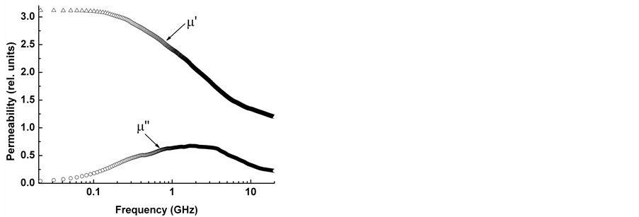
Figure 1. Permeability spectra of the sample 1 with CIP content of 9%.
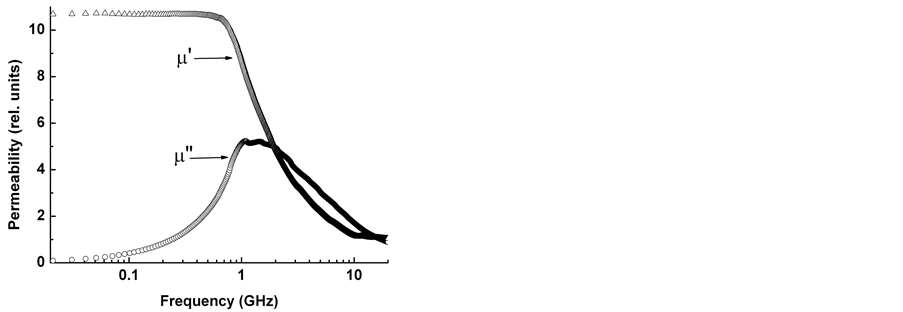
Figure 2. Permeability spectra of the sample 2 with CIP content of 53%.
CIP, the imaginary permeability component decreases with frequency much more slowly.
Figure 3 and Figure 4 shows the frequency dependence of the reflection coefficients of the layers located on the metal surface calculated according to formula (2). The obtained above values of μ and e samples 1 and 2 are used in the calculations. Numbers near the curves-sample thicknesses in mm.
Presented in Figure 3, Figure 4 results demonstrated that on the base of sample 1 and 2 it is difficult to make a single-layer RAC with the reflection coefficient less than −10 dB for the frequency band exceeding the octave.
3.3. Two-Layer EMWA SHF Range
We investigated a two-layer absorber design whose absorbing layer on metal surface was formed by the composite sample 2 (thick d1) and whose matching layer was formed by the sample 1 (thick d2) with small values of the permeability and permittivity. The calculation was performed according to the formulas (8) and (9). The simulation results presented on Figure 5 by solid lines.
Curve 1—the calculation for the absorbing layer thickness d1 = 0.9 mm, matching layer d2 = 2.3 mm. At such thicknesses reflection coefficient smaller −10 dB is observed in the frequency range from 3.1 to 17.1 GHz. Decrease in the thickness of the layers to d1 = 0.78 mm and d2 = 1.95 mm leads to a shift of the frequency band with a reflection coefficient ≤−10 dB in the high frequency region from 4 to 20 GHz (curve 2).
The points in Figure 5—experimental curve measured in the coaxial short-circuited line size of 7/3.05 mm. Measurements were performed on a two-layer construction with thickness d1 = 1 mm (sample 2) and d2 = 2 mm (sample 1). It can be seen that the deviation from of optimal thickness in the experimental RAC resulted in an increase of the reflection coefficient in the region of frequencies from 6 to 11 GHz. Thus, the use of bilayer RAC leads to substantial expansion of the band of operating frequencies as compared with monolayer.
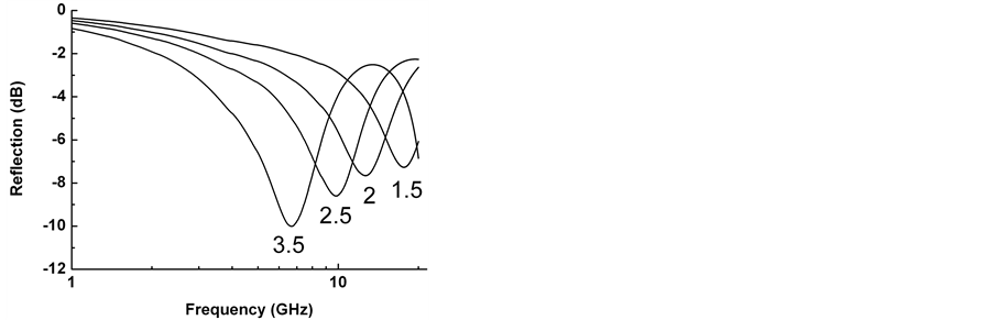
Figure 3. Reflection coefficients of the sample 1 calculated for different sample thicknesses. The numbers near the curves-RAC thickness in mm.

Figure 4. Reflection coefficients of the sample 2 calculated for different sample thicknesses. The numbers near the curves-RAC thickness in mm.
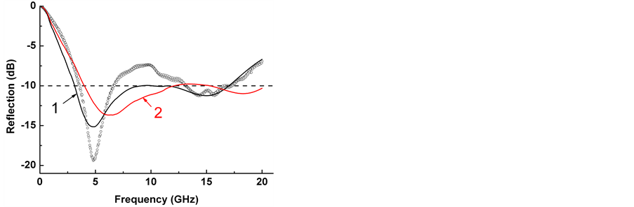
Figure 5. Reflectivity of two-layer RAC. Solid lines—calculation. Curve 1: d1 = 0.9 mm, d2 = 2.3 mm. Curve 2: d1 = 0.78 mm, d2 = 1.95 mm. Point —an experimental results on a sample with thickness d1 = 1 mm, d2 = 2 mm.
3.4. Single-Layer and Two-Layer EMWA EHF Range
This section presents the results of experimental investigations of the absorbing properties of composites samples 1 and 2 for frequencies in the range 26 - 37 GHz. Measurements were performed using the rectangular horn antennas 5 cm long and 2 × l cm2 antenna apertures. The SWR of the system of horn antennas without sample in the examined frequency range did not exceed 1.2.
Figure 6 shows the reflection coefficient of RAC located on the metal surface.
Here curve 1 is for sample 1 with thickness of d = 1 mm, curve 2 is for sample 2 (d = 1 mm), and curve 3 is for a two-layer design consisting of sample 1 (d2 = 1 mm) and sample 2 (d1 = 1 mm). From the figure it can be seen that the two-layer structure has the reflection coefficient much less than the single-layer structure, and a minimum of reflection is observed at frequencies greater than 37 GHz. As previously, sample 1 with the small content of CIP plays the role of a matching layer.
Figure 7 shows the results of investigations of the electromagnetic wave absorbers in the transmission/ref- lection mode. Values of the transmission and the reflection coefficients in decibels were measured. Then the measured values were recalculated into the transmission coefficient T and the reflection coefficient R on power in percent. The absorption coefficient was calculated from the formula A = 100 − R − T.
Figure 7(a) shows the measured values for sample 1. It can be seen that the reflection coefficient does not exceed 20%, and the transmission and absorption coefficients are close in values (about 40%). The corresponding values measured for sample 2 are shown in Figure 7(b). For this material with large CIP content, the reflection coefficient is somewhat higher. However, the absorbing properties of these RAC are almost twice greater. The transmission coefficient is about 1%. Figure 7(c) shows the measured values for the two-layer RAC design with 1-mm thick sample 1 used as a matching layer and sample 2 also with a thickness of 1 mm used as an absorbing layer. It can be seen that the two-layer absorber of electromagnetic waves in the given range of frequencies has the absorption coefficient greater than 90% and the reflection coefficient smaller than 10%. The transmission coefficient is small; it does not exceed 1%. Thus, good microwave properties of composites based on CIP observed in the EHF range. This is due to the wide frequency band in which there are losses on EFMR.
3.5. Study of the Samples 1 and 2 in the Terahertz Frequency Range
The electromagnetic response of samples 1 and 2 was also investigated in frequency range 150 - 525 GHz. The terahertz spectrometer STD-21 with backward-wave oscillators were used as a source of electromagnetic wave. We investigated the frequency dependence of transmission and reflection coefficients. The results of measuring complex permittivity in this frequency range are shown in Figure 8 and Figure 9.
It can be seen that the real and imaginary parts of permittivity vary slightly within a given range of frequencies. Determined from experiments values of permittivity correlate with the above performed estimates for e in SHF range.
Transmission, reflection and absorption coefficient on power for samples 1 and 2 are shown in Figure 10 and Figure 11.
Figure 10 and Figure 11 shows that the transmission coefficient for both samples is small and does not
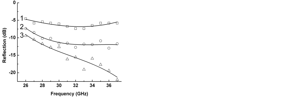
Figure 6. Reflection coefficients from RAC on the metal surface. Curve 1: sample 1 (d = 1 mm). Curve 2: sample 2 (d = 1 mm). Curve 3: two- layer RAC: the sample 1 (d2 = 1 mm) + sample 2 (d1 = 1 mm).
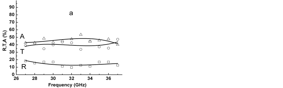
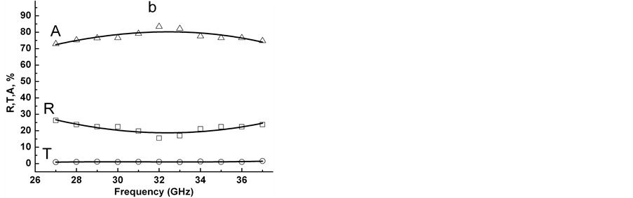
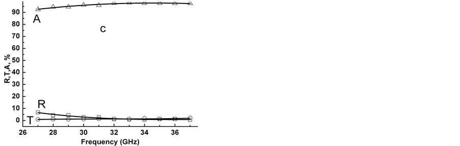
Figure 7. RAC reflection (R), transmission (T), and absorption (A) coefficients. (a) sample 1 (d = 1 mm); (b) sample 2 (d = 1 mm); (c) double layer RAC: the sample 1 (d2 = 1 mm) + sample 2 (d1 = 1 mm).
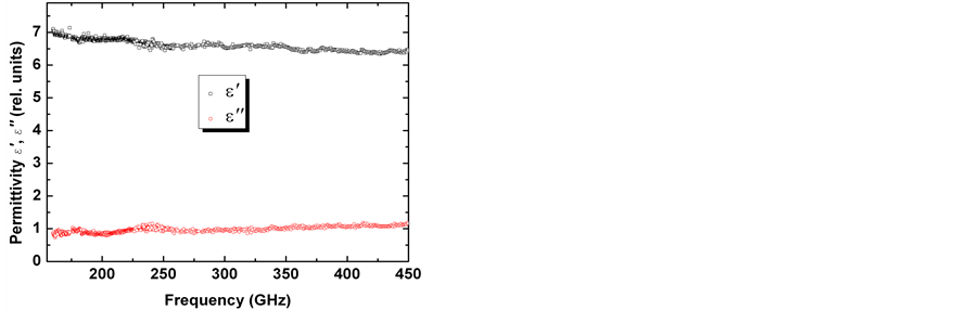
Figure 8. Permittivity spectra of sample 1.

Figure 9. Permittivity spectra of sample 2.
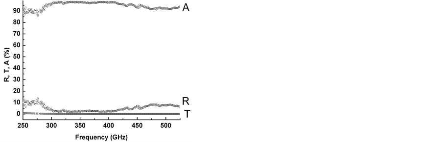
Figure 10. The reflection (R), transmission (T) and absorption (A) coefficients of the sample 1.
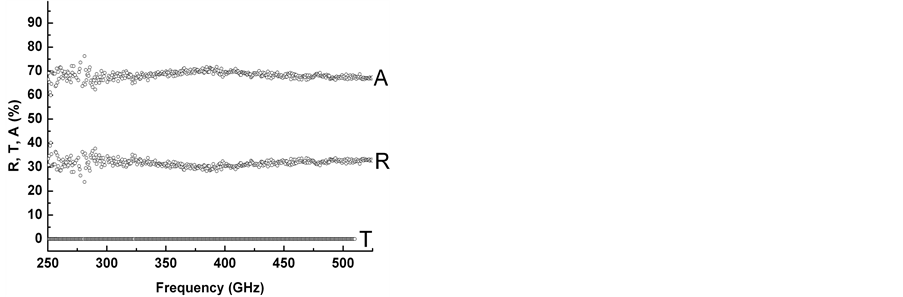
Figure 11. The reflection (R), transmission (T) and absorption (A) coefficients of the sample 2.
exceed 1%. For the sample with low content of CIP reflectance in the investigated frequency range does not exceed 10% and that of sample 2, it is about 30%. The remainder part of EMW power is absorbed. Thus, investigated composites have good absorbing properties in the terahertz frequency range.
4. Conclusion
Thus, studies of the permeability and permittivity spectra of the two samples of composites containing CIP in SHF range are carried out. Studies of different designs EMWA have shown that two-layer composite materials based on CIP with different filling factor allow selective absorption with a low reflectance in the SHF and EHF frequency bands. They can be used both as a masking coatings disposed on a metal surface, and as a protective nonreflecting coating with small reflection and transmission coefficients. Sample 1 exhibits good RAC properties also in the frequency range from 250 to 525 GHz.
Acknowledgements
Authors would like to thank center of Tomsk Regional Common Use Center: Center of radio-physics measurements, diagnostic and researching of parameters of natural and artificial materials (e-mail: susl@mail.tsu.ru) [19] .
This work was supported by RFBR grant No. 13-02-12240.
References
- Bystrov, R.P., Dmitriev, V.G., Zemskii, Yu.A., Perunov, Yu.M. and Cherepenin, V.A. (2012) Special Features of the Development of the Radio-Technical Systems of the Radio-Electronic Struggle. Uspekhi Sovremennoi Radioelektroniki (Achievements of Modern Radioelectronics), 8, 3-28.
- Wang, M., Duan, Y.P., Liu, S.H., Li, X.G. and Ji, Z.J. (2009) Absorption Properties of Carbonyl-Iron/Carbon Black Double-Layer Microwave Absorbers. Journal of Magnetism and Magnetic Materials, 321, 3442-3446. http://dx.doi.org/10.1016/j.jmmm.2009.06.040
- Liu, L., Duan, Y., Liu, S., Chen, L. and Guo, J. (2010) Microwave Absorption Properties of One Thin Sheet Employing Carbonyl-Iron Powder and Chlorinated Polyethylene. Journal of Magnetism and Magnetic Materials, 322, 1736- 1740. http://dx.doi.org/10.1016/j.jmmm.2009.12.017
- Cheng, Y.L., Dai, J.M., Wu, D.J. and Sun, Y.P. (2010) Electromagnetic and Microwave Absorption Properties of Carbonyl Iron/La0.6Sr0.4MnO3 Composites. Journal of Magnetism and Magnetic Materials, 322, 97-101. http://dx.doi.org/10.1016/j.jmmm.2009.08.037
- Zhuravlev, V.A., Suslyaev V.I. and Korovin, E.Yu. (2010) Dynamic Magnetic Characteristics of a Composite Polymeric Material Based on Carbonyl Iron. Russian Physics Journal, 53, 541-543. http://dx.doi.org/10.1007/s11182-010-9456-4
- Zhuravlev, V.A., Suslyaev V.I., Dotsenko, O.A. and Babinovich, A.N. (2011) Composite Radio-Absorbing Material Based on Carbonyl Iron for Millimeter Wavelength Range. Russian Physics Journal, 53, 874-876. http://dx.doi.org/10.1007/s11182-011-9502-x
- Tan, Y., Tang, J., Deng, A., Wu, Q., Zhang, T. and Li, H. (2013) Magnetic Properties and Microwave Absorption Properties of Chlorosulfonated Polyethylene Matrices Containing Graphite and Carbonyl-Iron Powder. Journal of Magnetism and Magnetic Materials, 326, 41-44. http://dx.doi.org/10.1016/j.jmmm.2012.08.021
- Xu, Y., Zhang, D., Cai, J., Yuan, L. and Zhang, W. (2013) Microwave Absorbing Property of Silicone Rubber Composites with Added Carbonyl Iron Particles and Graphite Platelet. Journal of Magnetism and Magnetic Materials, 327, 82-86. http://dx.doi.org/10.1016/j.jmmm.2012.09.045
- Ding, Q., Zhang, M., Zhang, C. and Qian, T. ( 2013) Synthesis and Absorbing Mechanism of Two-Layer Microwave Absorbers Containing Polycrystalline Iron Fibers and Carbonyl Iron. Journal of Magnetism and Magnetic Materials, 331, 77-81. http://dx.doi.org/10.1016/j.jmmm.2012.11.005
- Zhang, W., Bie, S., Chen, H., Lu, Y. and Jiang, J. (2014) Electromagnetic and Microwave Absorption Properties of Carbonyl Iron/MnO2 Composite. Journal of Magnetism and Magnetic Materials, 358-359, 1-4. http://dx.doi.org/10.1016/j.jmmm.2014.01.033
- Gurevich, A.G. and Melkov, G.A. (1996) Magnetization Oscillations and Waves. CRC Press, Boca Raton.
- Baker-Jarvis, J., Janezic, M.D., Grosvenor Jr., J.H. and Geyer, R.G. (1993) Transmission/Reflection and Short-Circuit Line Methods for Measuring Permittivity and Permeability. NIST Technical Note 1355.
- Brekhovskikh, L.M. (1973) Waves in Layered Media. Nauka.
- Belyaev, B.A., Zhuravlev, V.A., Kirichenko, V.I., Suslyaev, V.I. and Tyurnev, V.V. (1992) Use of an Irregular Microstrip Resonator to Investigate Microwave Properties of Dielectrics with Broad Conductivity Ranges. Measurement Techniques, 35, 992-994. http://dx.doi.org/10.1007/BF00977452
- Suslyaev, V.I., Kochetkova, T.D., Zhuravlev, V.A. and Sudakov, S.V. (2003) An Automated Setup for Investigating the Temperature Dependence of the Permittivity Spectra of Polar Liquids in the Range of 0.1 - 1.25 GHz. Instruments and Experimental Techniques, 46, 672-676. http://dx.doi.org/10.1023/A:1026097923322
- Naiden, E.P., Suslyaev, V.I., Bir, A.V. and Politov, M.V. (2004) Permeability Spectra Hexaferrite Nanopowders. Journal of Structural Chemistry, 45, 102-105. http://dx.doi.org/10.1007/s10947-006-0102-5
- Zhuravlev, V.A. and Suslyaev, V.I. (2006) Analysis of the Microwave Magnetic Permeability Spectra of Ferrites with Hexagonal Structure. Russian Physics Journal, 49, 1032-1037. http://dx.doi.org/10.1007/s11182-006-0220-8
- Zhuravlev, V.A. and Suslyaev, V.I. (2006) Analysis and Correction of the Magnetic Permeability Spectra of Ba3Co2Fe24O41 Hexaferrite by Using Cramers-Kronig Relations. Russian Physics Journal, 49, 840-846. http://dx.doi.org/10.1007/s11182-006-0183-9
- The Electronic Resource. http://www.ckp.tsu.ru/ckp_3/