Materials Sciences and Applications
Vol.5 No.1(2014), Article ID:42225,6 pages DOI:10.4236/msa.2014.51004
Alloyed CdTe0.6S0.4 Quantum Dots Sensitized TiO2 Electrodes for Photovoltaic Applications
![]()
1Department of Physics, Faculty of Science, Taif University, Taif, KSA; 2Department of Mathematical and Physical Engineering, Faculty of Engineering (Shoubra), Benha University, Cairo, Egypt; 3Department of Physics, Faculty of Science, Aljouf University, Aljouf, KSA.
Email: adaraghmeh@yahoo.com
Copyright © 2014 Ali Badawi et al. This is an open access article distributed under the Creative Commons Attribution License, which permits unrestricted use, distribution, and reproduction in any medium, provided the original work is properly cited. In accordance of the Creative Commons Attribution License all Copyrights © 2014 are reserved for SCIRP and the owner of the intellectual property Ali Badawi et al. All Copyright © 2014 are guarded by law and by SCIRP as a guardian.
Received November 18th, 2013; revised December 21st, 2013; accepted January 9th, 2014
KEYWORDS
Alloyed CdTe0.6S0.4; Quantum Dot; Quantum Dots Sensitized Solar Cell; Photovoltaic Cell
ABSTRACT
The photovoltaic performance of alloyed CdTe0.6S0.4 quantum dot sensitized solar cells (QDSSCs) is investigated. Fluorine doped Tin Oxide (FTO) substrates were coated with 20 nm-diameter TiO2 nanoparticles (NPs). Presynthesized colloidal solution of alloyed CdTe0.6S0.4 quantum dots (QDs) of 4.2 nm was deposited onto TiO2 NPs substrates using direct adsorption (DA) technique, by dipping for different times at ambient conditions. The FTO counter electrodes were coated with platinum, while the electrolyte containing I−/I−3 redox species was sandwiched between the two electrodes. Compared to pure CdTe QDs and CdS QDs, CdTe0.6S0.4 QDs showed better photovoltaic performance. The J-V characteristic curves of the assembled QDSSCs were measured at AM 1.5 simulated sunlight. The short current density (Jsc) and efficiency (η) increase with dipping time. At 24 h dipping time, the open-circuit photovoltage Voc, Jsc, fill factor (FF), and η were 0.46 volts, 1.54 mA/cm2, 0.43% and 0.31%, respectively.
1. Introduction
In the last two decades, semiconductor quantum dots (QDs) or nanoparticles (NPs) have been under intensive investigations, due to their unique size-dependent optical, electrical, thermal and magnetic properties [1-5], especially when their size is below the corresponding exciton radius. These attractive properties make QDs an important candidate in many applications such as, high efficiency thin film transistors, light-emitting diodes [6], electron-beam pumped lasers, electroluminescent devices and others [7,8]. Recently, QDs have become one of the most promising materials in solar cell fabrication [4,9, 10]. This third generation of solar cells is called quantum dots sensitized solar cells (QDSSCs). Tuning QDs properties by changing the particle size may cause problems in some applications, in particular, if unstable small particles (less than 2 nm) are used [11]. To overcome these problems, a new class of alloyed semiconductor nanoparticles (NCs) have been studied [11,12] to provide a way for continuous tuning of their energy band gap without changing the particle size. Alloyed ABxC1−x NCs are becoming increasingly important in many areas of nanoscale engineering through gradual variation of the composition variable x [13-17]. Alloyed CdTexS1−x QDs band gap can be adjusted to harvest the visible region of the solar spectrum by varying the tellurium molar ratio. This makes CdTexS1−x QDs a potentially favorable material for photovoltaic solar cell applications, where QDs of the same size but with varying optical properties might be preferable. QDs are deposited onto a mesoporous large band of semiconductors such as TiO2 NPs [18,19], ZnO NPs [19], and SnO2 NPs [20] to harvest the incident solar power. Mainly, two different strategies are used [4,21]: in situ growth of QDs by either a chemical bath deposition (CBD) containing both cationic and anionic precursors [18] or the successive ionic layer adsorption and reaction deposition (SILAR) method [22]. These methods provide good surface coverage, but they limit the control of QD size and yield a broad size distribution [23]. These drawbacks can be avoided if the QDs are synthesized prior (ex situ) to being deposited [24] via electrophoretic deposition (EPD) [23], linker-assisted adsorption (LA) [25], or direct adsorption (DA) [16,26] using different dipping times. The last method was the one applied in this work. Figure 1 shows an artistic depiction of the basic design of a QDSSC.
In this work, we synthesize alloyed CdTe0.6S0.4 QDs by organometallic pyrolysis method to be used as sensitizers in QDSSCs. These colloidal QDs were adsorbed onto TiO2 NPs by DA technique for different dipping times under ambient conditions. The photovoltaic characteristic parameters, short circuit current density (Jsc), open circuit voltage (Voc), fill factor (FF), and efficiency (η) for energy conversion) of alloyed CdTe0.6S0.4 QDSSCs were studied for four dipping times (1 h, 3 h, 6 h, and 24 h). To the best of our knowledge, this is the first time that DA technique has been used to deposit such kind of QDs onto TiO2 NPs to assemble QDSSCs.
2. Experiment
2.1. Preparation of Alloyed CdTe0.6S0.4 QDs
Alloyed CdTe0.6S0.4 QDs sample was synthesized as the method of Talapin et al. [27] by varying the amount of the second precursor. Cadmium solution was prepared by 0.3 g of CdO added to 3.0 g of stearic acid, and heated up to 170˚C till the red color of CdO disappears to ensure that the reaction between CdO and stearic acid is complete and CdO completely transform to Cd sterate. 2.0 g of tri-n-octylphosphine oxide (TOPO) and 1.0 g of hexadecyleamine (HDA) are added to the reaction mixture and heated at 200˚C. Tellurium solution was prepared by mixing 0.1 g of tellurium in 0.1 mL trioctylphosphine (TOP). Sulfur solution was also prepared by dissolving 0.2 g of sulphur 2.0 mL (TOP). Appropriate amounts of sulfur and tellurium solutions were mixed together to give the desired ratio (Te/S: 0.6/0.4). The mixture was then injected into the cadmium solution at a temperature
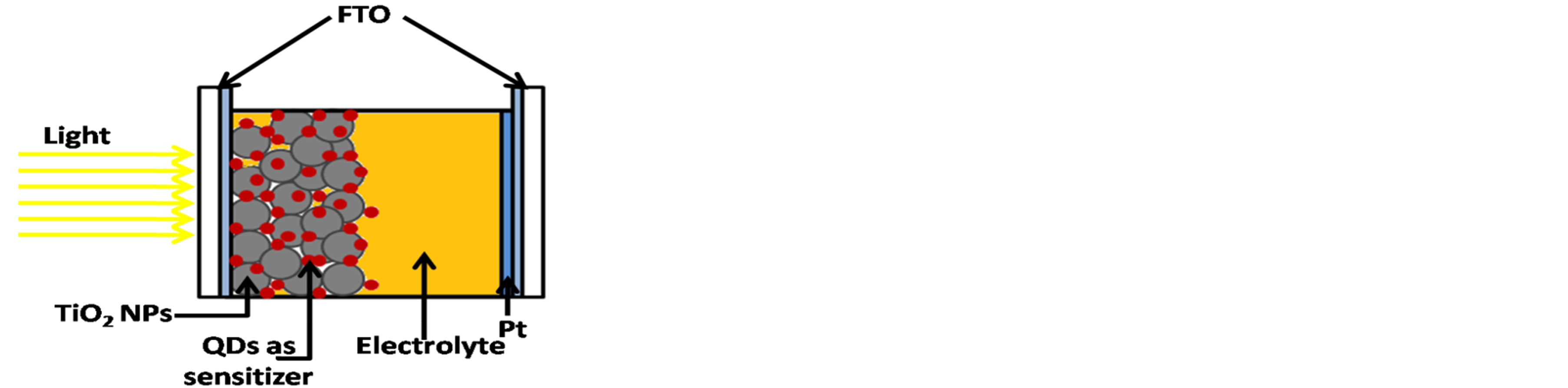
Figure 1. A depiction of the basic design of a QDSSC.
200˚C. A QDs sample with molar ratios (x = 0.6) was obtained from the reaction mixture at time interval of 5 minutes. The sample was separated using centrifuge. It was then washed several times with methanol to remove excess ligands. The QDs were precipitated with toluene at room temperature.
2.2. Preparation of Solar Cell Electrodes
A colloidal paste of TiO2 NPs was prepared by the method of G. Syrrokostas et al. [28]. Three grams of commercial TiO2 nanopowder (20 nm) (Degussa P-25) was ground in a porcelain mortar and mixed with a small amount of distilled water (1 ml) containing acetyl acetone (10% v/v) to create the paste. Acetyl acetone was used as a dispersing agent, since it prevents coagulation of TiO2 nanoparticles and affects the porosity of the film. The paste was diluted further by slow addition of distilled water (4 ml) under continued grinding. The addition of water controls the viscosity and the final concentration of the paste. Finally, a few drops of a detergent (Triton X-100) were added to facilitate the spreading of the paste on the substrate, since this substance has the ability to reduce surface tension, resulting in even spreading and reducing the formation of cracks. The TiO2 paste was deposited on a conducting glass substrate of SnO2:F with sheet resistance of 7 Ω/sq and >80% transmittance in the visible region, using a simple doctor blade technique. This was followed by annealing at 450◦C for 30 min. and the final thickness was 8µm after the solvent evaporation. Then the TiO2 films were dipped into a colloidal solution of pre-synthesized alloyed CdTe0.6S0.4 QDs to form working electrodes for different times (1 h, 3 h, 6 h, and 24 h). The counter electrodes were prepared by coating another FTO substrate sheet with a resistance of 7 Ω/sq with Pt.
2.3. Assembly of QDSSC
The Pt counter electrode and alloyed CdTe0.6S0.4 QDs sensitized TiO2 electrode were assembled as a sandwich type cell using clamps. Both electrodes were sealed using a hot-melt polymer sheet (solaronix, SX1170-25PF) of 25 µm thickness in order to avoid evaporation of the electrolyte. Finally, Iodide electrolyte solution was prepared by dissolving 0.127 g of 0.05 M Iodine (I2) in 10 mL of water-free ethylene glycol, then adding 0.83 g of 0.5 M potassium iodide (KI). The electrolyte was inserted in the cell with a syringe, filling the space between the two electrodes.
2.4. Measurements
The sizes of the QDs were measured by high resolution transmission electron microscope (HRTEM) (JEOL JEM- 2100 operated at 200 KV and equipped with Gatan CCD higher resolution camera). X-ray diffraction (XRD) patterns were carried out with an automated powder diffractometer (Bruker D8-advace diffractometer) with Cu X-ray tube (Wavelength: kα1 = 1.540598), the tube potential is 40 KV and the current is 40 mA. The alloyed CdTe0.6S0.4 QDs absorption spectra QDs (before and after adsorption on TiO2 electrodes) were recorded using a UV-Visible spectrophotometer (JASCO V-670). In addition, The current density-voltage (J-V) characteristics were recorded (with a Keithley 2400 voltage source/ammeter using GreenMountain IV-Sat 3.1 software), with the alloyed CdTe0.6S0.4 QDSSCs subjected to the irradiation of a solar simulator (ABET technologies, Sun 2000 Solar Simulators, USA) operating at 100 mW/cm2 (AM1.5G). A Leybold certified silicon reference solar cell (Model: [57863]) were used to calibrate the incident solar illumination. The J-V characteristic curves of alloyed CdTe0.6S0.4 QDSSC was also studied at various illumination intensities using attenuators and calibrated by the previous Si reference solar cell. All experiments were carried out under ambient conditions.
3. Results and Discussion
3.1. Characterization of Alloyed CdTe0.6S0.4 QDs
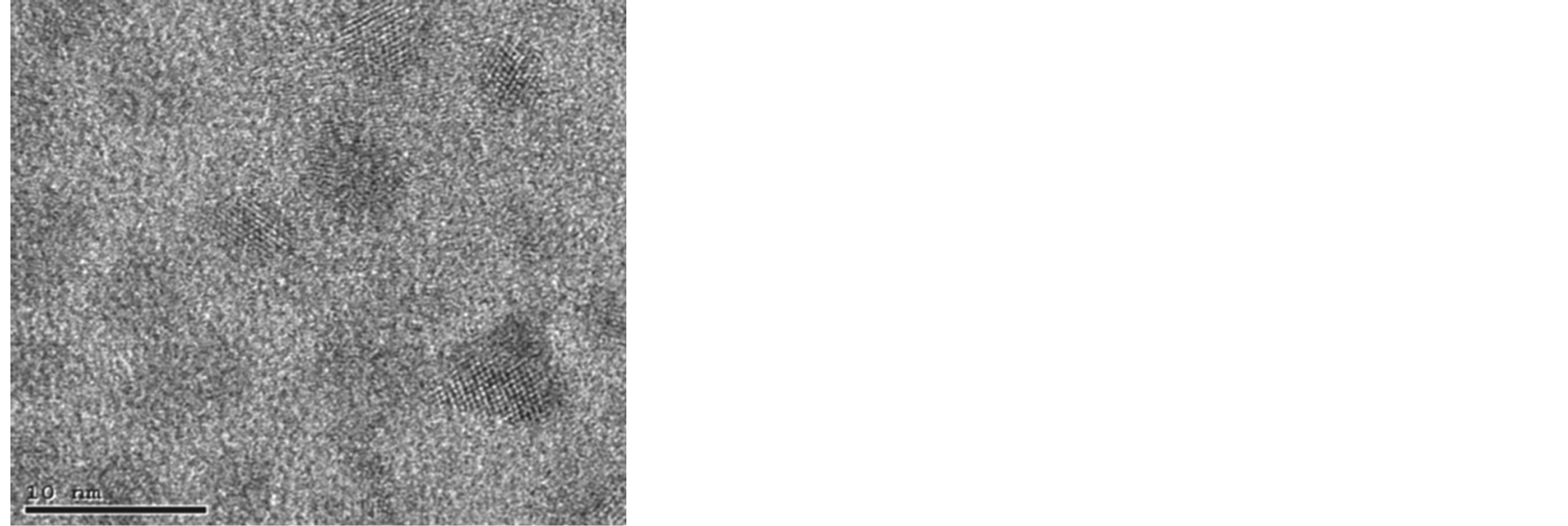
The average particle size distribution of the synthesized CdTe0.6S0.4 QDs was measured using HRTEM (JEOL 311UHR operated at 300 KV). Specimens were prepared by depositing a drop of hexane solution onto a Formvarcoated copper grid and letting it to dry in air. Figures 2(a) and (b) show the HRTEM micrograph and a histogram of particle size distribution for CdTe0.6S0.4 QDs respectively. It is observed that the particles size of the sample was about 4.2 ± 0.3 nm.
The alloyed CdTe0.6S0.4 QDs were characterized using X-ray diffractometer. The diffraction patterns seemed to be single phase with cubic sphalerite structure only. However, trials to apply MAUD program for Rietveld analysis yield bad pattern fitting as a single phase. So, we applied X’pert HighScore Plus program to identify the phases present in the samples. Two phases were identified, CdS wurtzite hexagonal structure and CdTe cubic structure. The phase composition and crystal structure of one of the samples CdTe0.6S0.4 is further investigated applying Rietveld method. Figure 3 illustrates the pattern fitting resulting from the Rieveld analysis. The analysis yields a phase percentage of 58.2% for CdTe and 41.2% for CdS, which indicates that ternary alloys are formed.
Figure 4 shows the UV-Vis. absorption spectra of CdTe0.6S0.4 QDs in a colloidal solution. The excitonic absorption edge is easily observed at 610 nm which correspond to 2.03 eV energy band gap. The energy gap of the bulk (Eg (bulk) CdTe0.6S0.4 alloy) can be calculated using Vegard’s law as follows [14,29]:
 (a)
(a)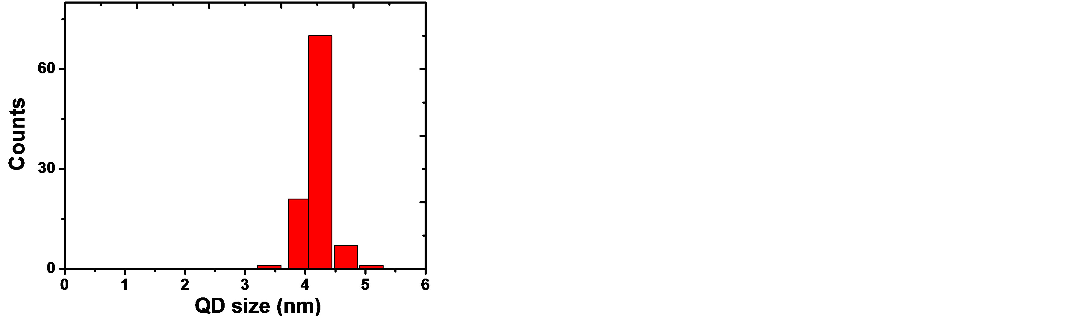 (b)
(b)
Figure 2. (a) HRTEM micrograph for CdTe0.6S0.4 QDs and (b) the histogram of particle size distribution.
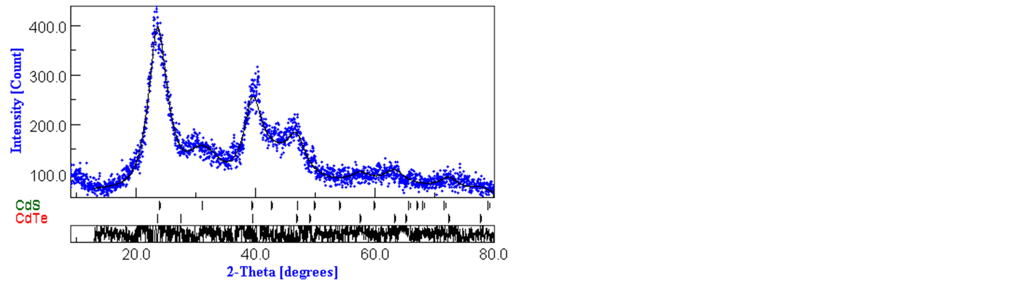
Figure 3. XRD pattern of alloyed CdTe0.6S0.4 QDs.
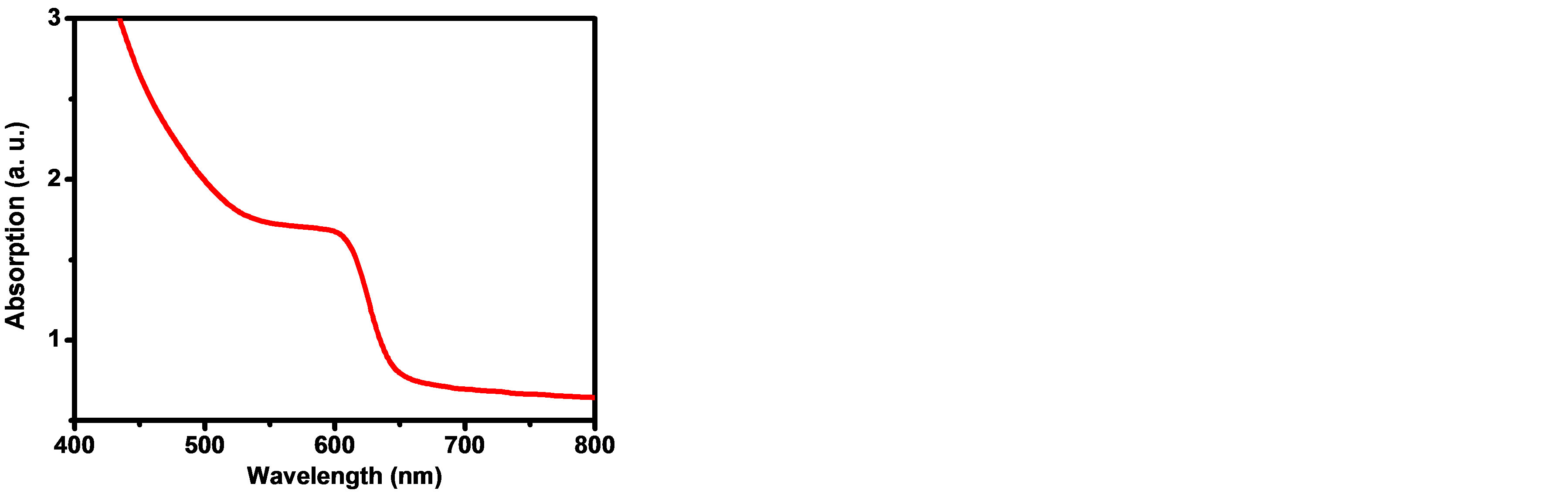
Figure 4. UV-Visible absorption spectrum for CdTe0.6S0.4 QDs.

Where χ stands for Eg (bulk) for CdTe (= 1.47 eV [30]) and for CdS = 2.42 eV [30], x (= 0.6) is the Te mole fraction, and b is the bowing parameter = 3.17 [13] for CdTexS1−x alloy. The calculated value of Eg (bulk) for CdTe0.6S0.4 alloy is 1.106 eV. The blue shift to shorter wavelength with respect to bulk CdTe0.6S0.4 alloy is due to the quantum confinement effect.
3.2. Characterization of CdTe0.6S0.4 QDs Sensitized TiO2 Electrodes (The Working Electrode)
The UV-Vis. absorption spectra of alloyed CdTe0.6S0.4 QDs sensitized TiO2 NPs electrode for different dipping times (0, 1 h, 3 h, 6 h, and 24 h) are shown in Figure 5. It is clearly seen that the absorption increases as the dipping time increases up to 24 hours, due to the increase of the adsorbed amount of alloyed CdTe0.6S0.4 QDs, while the onset of the absorption edge of CdTe0.6S0.4 QDs is clear at 24 hours dipping time as shown in Figure 5.
3.3. Characterization of Alloyed CdTe0.6S0.4 QDSSCs
The J-V characteristics curves of the assembled CdTe0.6S0.4 QDSSCs are shown in Figure 6 for four dipped times (1 h, 3 h, 6 h, 24 h) using TiO2 photoelectrodes and 100 mW/cm2 from a solar simulator. The values of Voc, Jsc, FF, and η of the assembled QDSSCs are given in Table 1. It is observed that both Jsc and η increase as the dipping time increases up to 24 hours. These results could be explained as follows; as the dipping time increases, the adsorbed amount of alloyed CdTe0.6S0.4 QDs increases, which leads to increase in the absorption of the incident light. Our earlier measurements of Jsc and η for CdTe QDSSCs [4] and CdS QDSSCs [16] having the same
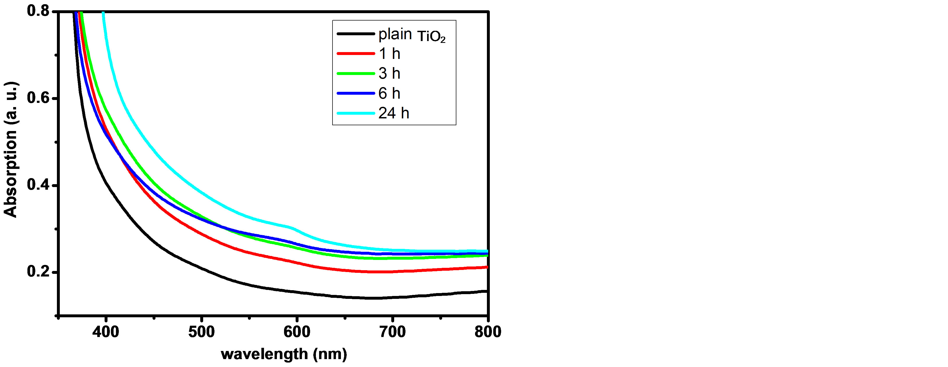
Figure 5. UV-Vis. absorption spectra of alloyed CdTe0.6S0.4 QDs/TiO2 electrode for different dipping times.
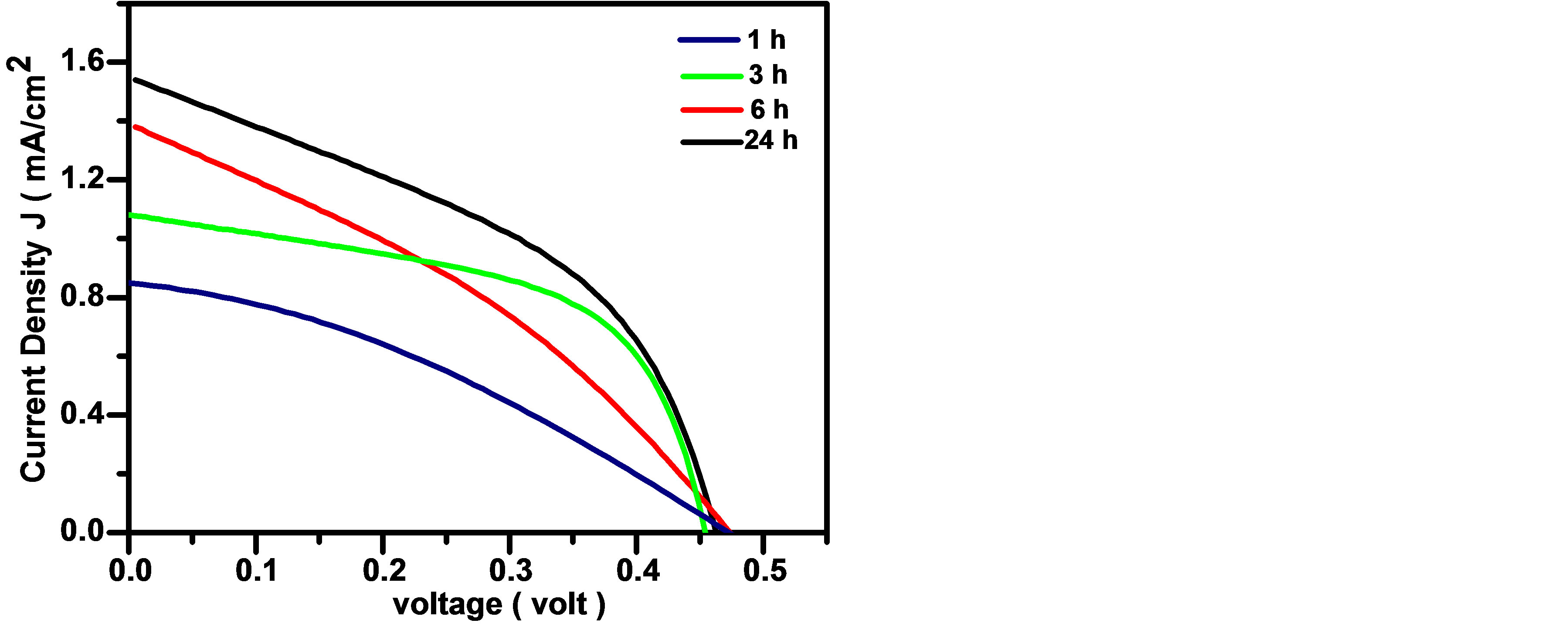
Figure 6. J-V characteristic curves of alloyed CdTe0.6S0.4 QDs QDSSCs for different dipping times.
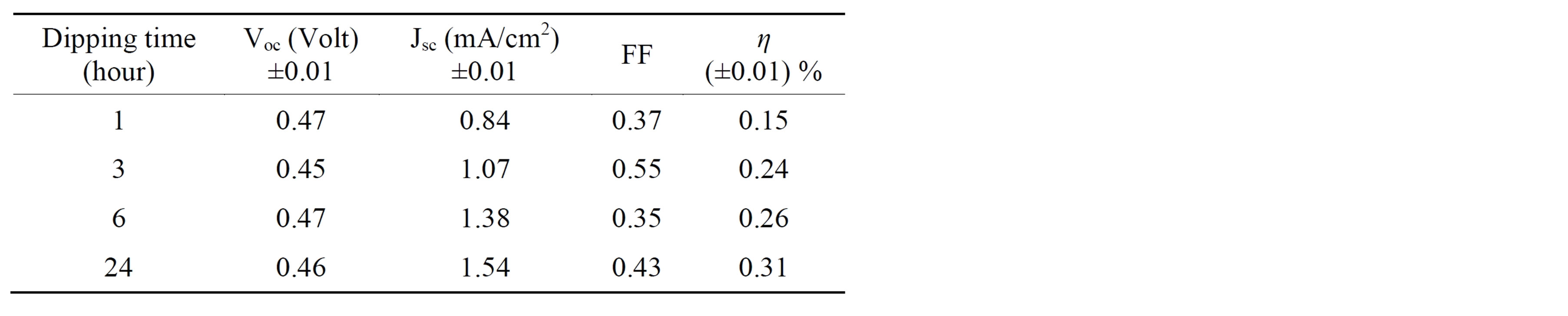
Table 1. J-V characteristics parameters of alloyed CdTe0.6S0.4 QDSSCs for different dipping times.
dipping time are 1.037 mA/cm2 and 0.18% for CdTe and 0.41 mA/cm2 and 0.11% for CdS. Therefore, Compared to pure CdTe QDs and CdS QDs, CdTe0.6S0.4 QDs show better photovoltaic performance. This enhancement of Jsc and η may result from improved photo-absorption efficiency, and charges separation of CdTe0.6S0.4 QDs, when Te/S approaches to 0.6/0.4, more interfaces between CdTe and CdS were formed, improving charges separation. Thus, more electrons can be injected to TiO2 electrode, leading to up-rise of TiO2 quasi-Fermi level and further increasing Jsc and η values. Additionally, the DA technique, which was used to deposit the alloyed CdTe0.6S0.4 QDs onto the TiO2 NPs, leads to the direct pinning of the alloyed CdTe0.6S0.4 QDs bands onto those of the TiO2 NPs without any energy barriers. This causes a direct electronic interaction between the two semiconductor materials (alloyed CdTe0.6S0.4 QDs QDs and TiO2 NPs). The DA technique minimises the electron injection time from the CBM of alloyed CdTe0.6S0.4 QDs to that of the TiO2 NPs.
Furthermore, Voc is approximately constant (= 0.46 ± 0.01 V) for all dipping times. Since the electrons inject quickly from the conduction band minimum (CBM) of alloyed CdTe0.6S0.4 QDs to the lowest conduction band (CB) energy of the TiO2 NPs, indicating that the CB level of TiO2 NPs and the valance band (VB) of the electrolyte dictate the Voc of the assembled QDSSCs.
4. Conclusion
Alloyed CdTe0.6S0.4 quantum dots (QDs) of 4.2 nm were adsorbed onto TiO2 nanoparticles (NPs) using the direct adsorption (DA) method, for different dipping times (0 to 24 h), as a sensitizer for solar cells. Our results show that both short current density (Jsc) and energy conversion efficiency (η) increase as the dipping time increases. The maximum values of Jsc and η are 1.54 mA/cm2 and 0.31% respectively for 24 h dipping time. The enhancement of Jsc and η may result from improving the photo-absorption efficiency, and charges separation of alloyed QDs. The open circuit voltage (Voc) is approximately constant (= 0.46 ± 0.1 volt) for all dipping times, since it is only dictated by the conduction band (CB) of TiO2 NPs and valance band (VB) of the electrolyte. The performance of such quantum dots sensitized solar cells (QDSSCs) can further be enhanced by tuning the QDs energy band gap to harvest more solar spectra.
Acknowledgements
The authors wish to thank Taif University for the grant research No. (1/433/1865). The Quantum Optics group at Taif University is also thanked for their assistance during this work.
REFERENCES
- N. Al-Hosiny, A. Badawi, M. A. A. Moussa, R. El-Agmy and S. Abdallah, “Characterization of Optical and Thermal Properties of CdSe Quantum Dots Using Photoacoustic Technique,” International Journal of Nanoparticles, Vol. 5, No. 3, 2012, pp. 258-266. http://dx.doi.org/10.1504/IJNP.2012.048022
- S. Baskoutas and A. F. Terzis, “Size Dependent Exciton Energy of Various Technologically Important Colloidal Quantum Dots,” Materials Science and Engineering: B, Vol. 147, No. 2-3, 2008, pp. 280-283. http://dx.doi.org/10.1016/j.mseb.2007.09.041
- J. Jiao, Z.-J. Zhou, W.-H. Zhou and S.-X. Wu, “CdS and PbS Quantum Dots co-Sensitized TiO2 Nanorod Arrays with Improved Performance for Solar Cells Application,” Materials Science in Semiconductor Processing, Vol. 16, No. 2, 2013, pp. 435-440. http://dx.doi.org/10.1016/j.mssp.2012.08.009
- A. Badawi, N. Al-Hosiny, S. Abdallah, S. Negm and H. Talaat, “Tuning Photocurrent Response through Size Control of CdTe Quantum Dots Sensitized Solar Cells,” Solar Energy, Vol. 88, 2013, pp. 137-143.
- S. Neeleshwar, C. L. Chen, C. B. Tsai, Y. Y. Chen, C. C. Chen, S. G. Shyu and M. S. Seehra, “Size-Dependent Properties of CdSe Quantum Dots,” Physical Review B, Vol. 71, 2005, Article ID: 201307(R).
- P. K. Khanna and N. Singh, “Light Emitting CdS Quantum Dots in PMMA: Synthesis and Optical Studies,” Journal of Luminescence, Vol. 127, 2007, pp. 474-482.
- D. Patidar, K. S. Rathore, N. S. Saxena, K. Sharma and T. P. Sharma, “Energy Band Gap and Conductivity Measurments of CdSe Thin Films,” Chalcogenide Letters, Vol. 5, No. 2, 2008, pp. 21-25.
- A. Badawi, N. Al-Hosiny, S. Abdallah, S. Negm and H. Talaat, “Photoacoustic Study of Optical and Thermal Properties of CdTe Quantum Dots,” Journal of Materials Science and Engineering A, Vol. 2, No. 1, 2012, pp. 1-6.
- J. Zhao, J. Wu, F. Yu, X. Zhang, Z. Lan and J. Lin, “Improving the Photovoltaic Performance of Cadmium Sulfide Quantum Dots-Sensitized Solar Cell by Graphene/ Titania Photoanode,” Electrochimica Acta, Vol. 96, 2013, pp. 110-116. http://dx.doi.org/10.1016/j.electacta.2013.02.067
- X. Wang, J. Zheng, X. Sui, H. Xie, B. Liu and X. Zhao, “CdS Quantum Dots Sensitized Solar Cells Based on Free-Standing and Through-Hole TiO2 Nanotube Arrays,” Dalton Transactions, Vol. 42, No. 41, 2013, pp. 14726- 14732. http://dx.doi.org/10.1039/c3dt51266e
- Y. Wang, Y. Hou, A. Tang, B. Feng, Y. Li, J. Liu and F. Teng, “Synthesis and Optical Properties of CompositionTunable and Water-Soluble ZnxCd1-xTe Alloyed Nanocrystals,” Journal of Crystal Growth, Vol. 308, 2007, pp. 19-25.
- R. E. Bailey and S. Nie, “Alloyed Semiconductor Quantum Dots: Tuning the Optical Properties without Changing the Particle Size,” Journal of the American Chemical Society, Vol. 125, No. 23, 2003, pp. 7100-7106.
- N. P. Gurusinghe, N. N. Hewa-Kasakarage and M. Zamkov, “Composition-Tunable Properties of CdSxTe1−x Alloy Nanocrystals,” The Journal of Physical Chemistry C, Vol. 112, No. 33, 2008, pp. 12795-12800.
- L. A. Swafford, L. A. Weigand, M. J. B. II, J. R. McBride, J. L. Rapaport, T. L. Watt, S. K. Dixit, L. C. Feldman and S. J. Rosenthal, “Homogeneously Alloyed CdSxSe1−x Nanocrystals: Synthesis, Characterization, and Composition/Size-Dependent Band Gap,” Journal of the American Chemical Society, Vol. 128, No. 37, 2006, pp. 12299- 12306. http://dx.doi.org/10.1021/ja063939e
- P. V. Kamat, “Quantum Dot Solar Cells. Semiconductor Nanocrystals as Light Harvesters,” The Journal of Physical Chemistry C, Vol. 112, No. 48, 2008, pp. 18737- 18753. http://dx.doi.org/10.1021/jp806791s
- S. Abdallah, N. Al-Hosiny and A. Badawi, “Photoacoustic Study of CdS QDs for Application in Quantum-DotSensitized Solar Cells,” Journal of Nanomaterials, Vol. 2012, 2012, p. 6.
- C.-W. Peng and Y. Li, “Application of Quantum DotsBased Biotechnology in Cancer Diagnosis: Current Status and Future Perspectives,” Journal of Nanomaterials, 2010, Article ID: 676839.
- Y. Xie, S. H. Yoo, C. Chen and S. O. Cho, “Ag2S Quantum Dots-Sensitized TiO2 Nanotube Array Photoelectrodes,” Materials Science and Engineering: B, Vol. 177, No. 1, 2012, pp. 106-111. http://dx.doi.org/10.1016/j.mseb.2011.09.021
- K. Tvrdy, P. A. Frantsuzov and P. V. Kamat, “Photoinduced Electron Transfer from Semiconductor Quantum Dots to Metal Oxide Nanoparticles,” PNAS, Vol. 108, No. 1, 2011, pp. 29-34. http://dx.doi.org/10.1073/pnas.1011972107
- S. J. Ikhmayies and R. N. Ahmad-Bitar, “Characterization of the SnO2:F/CdS:In Structures Prepared by the Spray Pyrolysis Technique,” Solar Energy Materials and Solar Cells, Vol. 94, No. 5, 2010, pp. 878-883. http://dx.doi.org/10.1016/j.solmat.2010.01.011
- S. Ruhle, M. Shalom and A. Zaban, “Quantum-Dot-Sensitized Solar Cells,” ChemPhysChem, Vol. 11, 2010, pp. 2290-2304.
- A. Kongkanand, K. Tvrdy, K. Takechi, M. Kuno and P. V. Kamat, “Quantum Dot Solar Cells. Tuning Photoresponse through Size and Shape Control of CdSe-TiO2 Architecture,” Journal of the American Chemical Society, Vol. 130, No. 12, 2008, pp. 4007-4015.
- A. Salant, M. Shalom, I. Hod, A. Faust, A. Zaban and U. Banin, “Quantum Dot Sensitized Solar Cells with Improved Efficiency Prepared Using Electrophoretic Deposition,” ACS NANO, Vol. 4, No. 10, 2010, pp. 5962-5968. http://dx.doi.org/10.1021/nn1018208
- N. Guijarro, T. Lana-Villarreal, I. Mora-Sero´, J. Bisquert and R. Go´mez, “CdSe Quantum Dot-Sensitized TiO2 Electrodes: Effect of Quantum Dot Coverage and Mode of Attachment,” The Journal of Physical Chemistry C, Vol. 113, No. 10, 2009, pp. 4208-4214.
- J. H. Bang and P. V. Kamat, “Quantum Dot Sensitized Solar Cells. A Tale of Two Semiconductor Nanocrystals: CdSe and CdTe,” ACS NANO, Vol. 3, No. 6, 2009, pp. 1467-1476.
- D. R. Pernik, K. Tvrdy, J. G. Radich and P. V. Kamat, “Tracking the Adsorption and Electron Injection Rates of CdSe Quantum Dots on TiO2: Linked versus Direct Attachment,” The Journal of Physical Chemistry C, Vol. 115, No. 27, 2011, pp. 13511-13519. http://dx.doi.org/10.1021/jp203055d
- D. V. Talapin, S. Haubold, A. L. Rogach, A. Kornowski, M. Haase and H. Weller, “A Novel Organometallic Synthesis of Highly Luminescent CdTe Nanocrystals,” The Journal of Physical Chemistry B, Vol. 105, No. 12, 2001, pp. 2260-2263. http://dx.doi.org/10.1021/jp003177o
- G. Syrrokostas, M. Giannouli and P. Yianoulis, “Effects of Paste Storage on the Properties of Nanostructured Thin Films for the Development of Dye-Sensitized Solar Cells,” Renewable Energy, Vol. 34, 2009, pp. 1759-1764.
- Y.-K. Kuo, B.-T. Liou, S.-H. Yen and H.-Y. Chu, “Vegard’s Law Deviation in Lattice Constant and Band Gap Bowing Parameter of Zincblende InxGa1−xN,” Optics Communications, Vol. 237, 2004, pp. 363-369.
- O. Madelung, “Semiconductors: Data Handbook,” 3rd Edition, Springer-Verlag, Berlin, 2004. http://dx.doi.org/10.1007/978-3-642-18865-7