Materials Sciences and Applications
Vol. 4 No. 4A (2013) , Article ID: 30457 , 8 pages DOI:10.4236/msa.2013.44A004
Investigation of Element Profiles, Defects, Phase Composition and Physical and Mechanical Properties of Superhard Coatings Ti-Hf-Si-N
![]()
Sumy State University, Sumy, Ukraine.
Email: alexp@i.ua
Copyright © 2013 Alexander D. Pogrebnjak. This is an open access article distributed under the Creative Commons Attribution License, which permits unrestricted use, distribution, and reproduction in any medium, provided the original work is properly cited.
Received February 4th, 2013; revised March 2nd, 2013; accepted April 1st, 2013
Keywords: Superhards; Coatings; Composition; Thermal Stability; Wear
ABSTRACT
This paper investigates the microstructure, physical, chemical and mechanical of superhard nanocomposite of Ti-Hf-Si-N. The coatings were grown by C-PVD method. Profiles of elements and vacancy-type defects (S-parameter measurements of the Doppler broadening of the annihilation peak DBAP) in the studied coatings were investigated. Defined and calculated the elastic modulus E, hardness H, friction, adhesion. Wear rate was determined as a function of the bias potential supplied to the substrate and the pressure in the chamber. The developed coatings have hardness of 37.8 to 48 GPa, the friction coefficient of 0.48 to 0.15, the grain size of the solid solution from 3.9 to 10.8 nm (depending on deposition conditions). It was found that positrons are trapped by defects at the junction of three or more nanograins interfaces. In some cases, there was formed two phases in coatings: a solid solution (Ti, Hf)N with different volume content of Hf in a solid solution, and an amorphous phase α-Si3N4 (the layer between the nanograins).
1. Introduction
It is well known that if the Si atoms add to TiN, a nanostructured nanocomposite coating Ti-Si-N is obtained, in which (at certain concentration of Si and N) two phases of TiN and SiN (Si3N4) can be formed [1-4]. In this case, the nanocomposite is very hard, the hardness values range from 40 to 50 GPa, and has an increased resistance to high temperatures up to 900˚C [1,3]. In [5,6], we demonstrated that the addition of Hf or Fe in the TiN, leads to formation of a solid solution (Ti; Hf)N and to increase of hardness up to 48 GPa. And the doping of Fe into this system leads to formation of two and three phases in the coating, i.e. the nanocomposite is formed. Using cathodic physical vacuum evaporation of the TiHf-Si target, a nanostructured coating with high physical and mechanical properties can be formed. It will be demonstrated in this work. From the literature it is well known that if nanograins size of several nanometers, developed by one or two monolayer’s of amorphous (or quasi-amorphous phase, such as BN, TiSi2, a-Si3N4), the coating will demonstrate a superhardness 40 < H < 80 GPa [4-15]. But such properties as the resistance to oxidation, high elastic modulus, and plasticity at the same time (non brittleness) are also of a great importance [16- 23].
2. Experimental Details
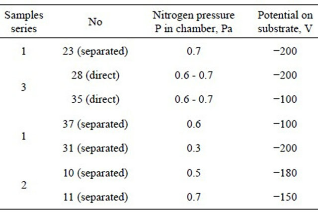
Samples of Ti-Hf-Si-N composition were deposited on substrates made of steel (St.3 - 0.3 wt% C, the rest is Fe) with polished surface of 20 mm diameter and 3 mm thick in a vacuum chamber with a vacuum in HF discharge, where a cathode made of sintered Ti35-Hf18-Si13 was used. To obtain nitrides the accelerator chamber was filled with atomic nitrogen at different pressures (see Table 1).
A Cathodic-Arc-Vapor-Deposition “Bulat-3T” with HF generator [3,5] was applied. Potential bias was applied to the substrate from the HF generator of pulsed damped oscillations with a frequency of <1 MHz. The duration of each pulse is of 60 µs, with a repetition rate of ~10 kHz. The amount of negative self-bias potential of the substrate caused by HF diode effect was 2 - 3 kV. Deposition parameters are given in Table 1. To investigate the elemental composition of coatings, methods of secondary ion mass spectrometry (SIMS), SAJW-05 spectrometer with quadrupole mass analyzer QMA-410 Balzers and glow discharge mass spectrometry (GD-MS), SMWJ-01
Table 1. Deposition parameters for different samples series of Ti-Hf-Si-N coatings
spectrometer with quadrupole mass analyzer SRS-300 were applied (Warsaw, Poland) [12,13]. For obtaining of complete information about the elemental composition of coatings the scheme of Rutherford backscattering (RBS) on He+ ions with an energy of 1.3 MeV (scattering angle θ = 170˚, for normal incidence of probing ions on the samples, the energy resolution of the detector 16 keV) was used. Dose of helium ions was 5 µC. For interpretation of RBS spectra the standard (international) program [4] of element profiles in depth measurement was used. To provide the elemental analysis a different accelerator (RBS) with He+ ions with energies of 1.7 MeV was used. The program used for interpreting of spectra was SIMNRA [5] (Dresden, Germany). A scanning electron microscope JEOL-7000F with microanalysis EDS (Japan) and transmission electron microscope JEOL 2010 F was also used for structure analysis of coatings. For the analysis of vacancy-type defects in the coatings slow positrons microbeam (Halle, Germany) was applied. Using this method the so called S-parameter was measured as a function of the incident positrons beam energy (1 - 20 keV) with the depth of analysis from a few nm to 2.1 µm [8-10].
Investigation of mechanical characteristics of the layers was carried by nanoindentation on the device Nanoindenter G200 (MES Systems, USA) with a three-sided Berkovich diamond pyramid with a radius of blunting the apex of about 20 nm. The accuracy of the depth measurement is ±0.4 nm. To reduce the influence of substrate on the measured hardness of samples, the indentation was carried out to a depth of 200 nm. In this case, the prints were applied at 15 µm apart. At least 5 measurements using continuous stiffness monitoring module CMA (continuous stiffness measurement) were made on each sample. Depth of the indentation was much less than 1/10 of the coatingfilms thickness [3]. Analysis of the load curve is made by the method of Oliver and Fahrr. X-ray diffraction analysis of nanos tructured films was carried out on two set-ups: DRON-4 (Russian Federation) and X’Pert PANalitical (Holland). The step size is 0.05˚, displacement speed is 0.05˚, U = 40 kV, I = 40 mA, the cathode-copper. Cross-sections of the system “coating-substrate” were prepared by an ion beam. On these crosssections the morphology, structure and elemental composition of coatings were analyzed.
Friction test by “finger-surface” method were held at the TAU-1M tribometer under dry friction conditions. The friction coefficient and wear resistance of films were determined by the reciprocating sliding, performed at room temperature (22˚C ± 1˚C) and relative humidity of 80% ± 5%. Velocity of the plate and the sample was 4 mm/s, rounded indenter radius of curvature of 0.5 mm was made of hard metal VK8 (hardness of 87.5 HRC), the load on the indenter was 1 N. To determine the adhesive/cohesive strength, scratch resistance, and also to study the fraction mechanism the scratch tester REVETEST see (CSM Instruments) [6] was used (Figure 1). The scratches were applied to the coating surface at continuously increasing load by diamond spherical indenter “Rockwell C” with a radius of curvature of 200 µm. Simultaneously the power of acoustic emission, friction coefficient and the penetration depth of the indenter and the value of the normal load (FN) were recorded. Three scratches were applied to each sample.
Tests were carried out under the following conditions: the load on the indenter increased from 0.9 to 70 N, speed of the indenter movement was 1 mm/min, scratch length −10 mm, the loading rate −6.91 N/min, the frequency of a digital signal 60 Hz, acoustic emission 9 Db. Tests determined the minimum (critical) load LC1which corresponds to the beginning of the indenter penetration into the coating; LC2-top when the first cracks appear; LC3-the peel of some parts of coating; LC4-plas-
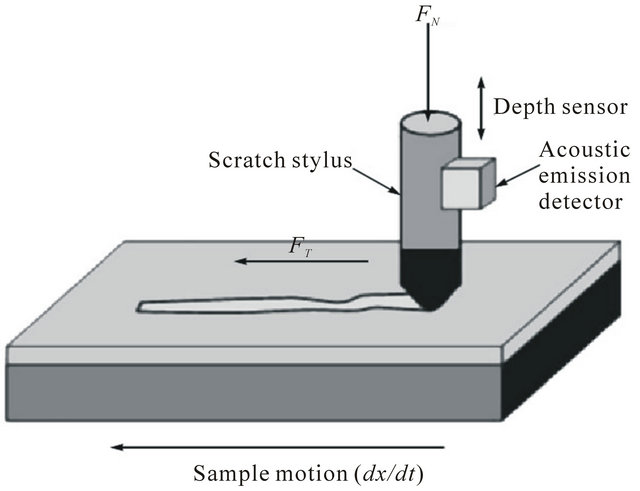
Figure 1. Experimental setup for the determination of the adhesive/cohesive strength. Designations: FN is the normal load, and FT is the friction force.
tic abrasion of the coating to the substrate. Registration, during a test, (a relatively large number of different physical parameters) improves the reliability and accuracy of the method the critical load determination. The deformation of the coating by the diamond indenter was investigated further using the integrated optical microscope and electron-ion scanning microscope Quanta 200 3D, equiped with an integrated system of Pegasus 2000 for microanalysis.
3. Experimental Results and Discussion
Before turning to the analysis of X-ray data, it should be noted that, for understanding of the sequence of processes occurring in the surface region during the deposition, it is necessary to compare the heat of formation of possible nitrides. In accordance with [7] ΔH298 (HfN) = −369.3 kJ/mol, ΔH298 (TiN) = −336.6 kJ/mol, ΔH298 (Si3N4) = −738.1 kJ/mol. It means that the heat of formation of all systems is a relatively large and negative, indicating that there is a high probability of the formation of such systems through the transfer of material from the target to the substrate. In this case, the proximity of the values of the heat of formation of TiN and HfN creates conditions for the formation of sufficiently homogeneous solid solution (Ti, Hf)N.
Since the X-ray study indeed revealed the formation of this particular two-phase system (because the diffraction peaks of this phase are between peaks from mononitrides TiN (JCPDS 38-1420) and HfN (JCPDS 33-0592)), so we identified this phase as a substitutional solid solution (Ti, Hf)N, and the diffused peaks of low intensity, which are present in the diffraction spectrum in the angular range of 2θ = 40˚ - 60˚, are apparently, related to the spectrum peaks of the second α-Si3N4 phase (Figure 2, curve 3). Conditions of formation of nanocomposite coating Ti-Hf-Si-N lead to significant lattice strain of the crystallites, so in the coating the compressive stresses are

Figure 2. Diffraction spectra of Ti-Hf-Si-N coatings, obtained for three series of samples.
occurring. Diffraction patterns shown in Figure 2 (curve 1 and 2), obtained by the separation of the ion-plasma flow, illustrate the definition of a crystal lattice deformation in samples series 3. In this case, we analyzed by imposing of lines in oblique mode (spectra), and determined that for the samples series 3 (curve 1) the deformation <Σ> = −1.9% (lattice parameter a = 0.4305 nm) and for the sample 11 of series 3 (curve 2) the deformation is <Σ> = −1.6% (the lattice parameter a = 0.4303 nm). Data analysis of X-ray diffraction show that the coating obtained from the target of the same composition are very different by the characteristic structural features, depending on the separation or non-separation (jet) beam. The results of this analysis are shown in Table 2.
Figure 3 shows that in the jet mode of the plasma flow without separation the non-textured polycrystalline coatings with sufficiently high relative intensity of the peaks (the latter, at a comparable coating thickness indicates a relatively high content in solid solution Hf, having a large reflectivity compared to Ti) are formed.
During the process of beam separation the produced (deposited) coatings are differently textured. In case of supplying the substrate by low potential (−100V) we get a texture with the [110]. Thus the structure of the coating is composed of textured and non-textured crystallites. The volume content of textured crystallites is about 40% of the total, and the lattice constant in comparison to nontextured crystallites increases. The most likely reason for this increase may be a non-uniform distribution of hafnium atoms in the coating with their primary content in the lattice of textured crystallites. Herewith the texturing leads to increase of the average crystallite size in the direction of the film-forming particles deposition (perpendicular to the growing surface). For example, in the fraction of non-textured crystallites their average size is 6.7 nm, while in the fraction of textured crystallites the size is much higher and is 10.6 nm. This type of coating is characterized by the highest value of nanohardness (see Table 2). In case of rising voltage up to −200 V and use
 (a) (b)
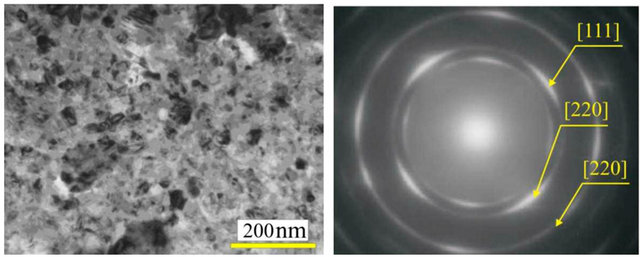
Figure 3. Images of structure areas of nanocomposite TiHf-Si-N coating, obtained by TEM JEOL 2010 F: (a) structure of surface; (b) dark-field image of nanograin structure.
Table 2. Results of measurements of tribomechanical properties for different samples series of Ti-Hf-Si-N coatings.
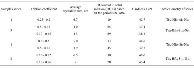
of scheme with separation during the deposition, the coating are formed with reduced average crystallite size (to 5.0 nm) and the fraction of textured crystallites (less than 20 vol%) is also significantly reduced. Herewith, the axis texture is oriented as [001]. It should also be noted that the rising of accelerating voltage from −100 to −200 V (i.e. increasing energy of the plasma flow) leads to formation of textured factions with the same value of the spatial period.
However, the magnitude of the lattice in this case exceeds a period of non-textured fraction formed when applying a low potential to the substrate and is 0.4337 nm. This is the period, assuming Vegard rule for solid solutions, corresponds to the content of 33 at% Hf in a metallic solid solution (Hf, Ti) of nitride phase (in the calculation the tabulated values of periods are used), TiN = 0.424173 nm (JCPDS 38-1420) and HfN = 0.452534 nm (JCPDS 33-0592) [3,15].
As it is known, the action of compressive stresses in the coating result in a reduction of the angle of the diffraction peak detected during the diffraction shooting by scheme θ - 2θ, and the corresponding calculation leads to an overestimation of the value of the period, i.e. to the overstate of the value of the Hf concentration in solid solution (the error may be 5 - 10 at%). Therefore, the calculations made here can give the information only about the upper limit of the concentration of Hf in solid solution. All of the above refer to the samples obtained at the typical pressure in the chamber 0.6 - 0.7 Pa during deposition process. In the case of reduction of pressure to 0.3 Pa, carried in the separation mode with a voltage of 200 V (series 1, No 31), an increase of the relative content of the heavier atoms of Hf in the coating is observed. In addition, during the reduction of pressure, the average size of the growing crystallites also decreases. The effects observed in this case can be associated with an increase in the radiation factor at low operating pressures. Indeed, lowering of the operating pressure must be accompanied by decrease of the probability of loss of energy by collisions atoms in the “target-substrate” gap. Thus, maintaining a relatively high energy of deposition, the film-forming atoms on the substrate stimulate the processes of secondary sputtering and radiation defectforming, which in first case leads to increase of the relative content of Hf atoms in the coating, and in the second case to increase of the nuclei number and, consequently, to the decrease of the average crystallite size in the coating. In the coatings obtained under a characteristic pressure 0.6 - 0.7 Pa in the absence of beam separation (in ramjet mode) a higher value of the lattice parameters are realized, which is determined by increasing content of Hf atoms (see Tables 1 and 2) [3]. Apparently, more intensive jet mode of deposition leads to decrease of the average crystallite size, the cause of which is the increasing density of nucleation at a time. In addition, to a more pronounced effect of reducing of the crystallites size can lead the use of a larger voltage (–200 V), which is natural, since the increase of the radiation factor promotes the dispersion structure [19].
Figure 3 presents the results obtained from the RBS investigation of the elemental composition of the superhard nanostructured Ti-Hf-Si-N films. It can be seen from this figure that, for the first series of samples with coatings (Figure 4, curve 1), the composition of the TiHf-Si-N films is described by the formula (Ti37Hf9Si8) N46.
The concentration distribution profiles of elements over the depth of the Ti-Hf-Si-N coating, which correspond to the RBS spectra (Figure 4), are calculated under the assumption that the atomic density of the layer is close to the atomic density of titanium nitride.
It is well known that Rutherford backscattering is a reference method for determining the concentration of elements with a large atomic number, as well as for determining the thickness of the films.
Furthermore, it is a nondestructive method, and this property is its advantage. At the same time, secondary ion mass spectrometry is a more sensitive method of analysis (the detection limit is ~10−6 at%) (Figure 5). Therefore, a comparison of the results obtained using the RBS, SIMS, and glow discharge mass spectrometry (GDMS) methods provides a more realistic picture of the distribution of the elemental composition of the coating over the depth of the layer. This has made it possible to analyze the composition of the film as a whole over the depth from the film surface to the film substrate interface, including the determination of concentrations of oxygen and carbon uncontrollable impurities, which come from the residual atmosphere in the working chamber.
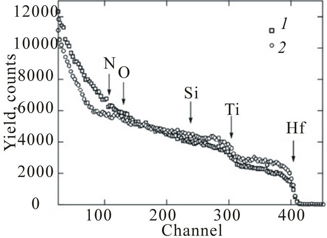
Figure 4. Energy spectra of Rutherford backscattering of He+ ions with an energy of 1.3 MeV for samples of the steel with the Ti-Hf-Si-N film: (7) at a potential of 100 V, p = 0.6 Pa (first series of samples), and (2) at a potential of 200 V, p = 0.7 Pa (second series of samples).
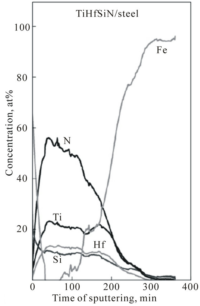
Figure 5. Concentration profiles of elements in the Ti-HfSi-N film according to the SIMS analysis for the first series of samples. The high Fe concentration is observed in the substrate material (steel).
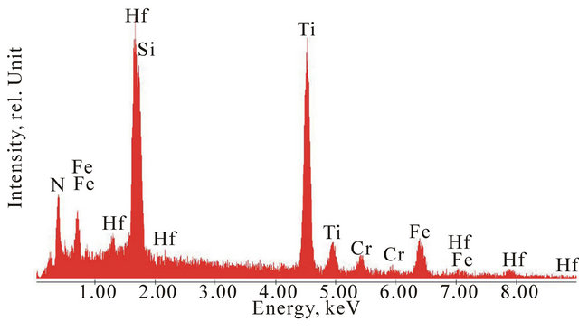
Figure 6(a) and (b) shows the energy dispersive spectra obtained from Ti-Hf-Si-N sample (Series 1). Figure 1(a) is the integral information from the area of 2 × 2 mm, and Figure 1(b) shows information about local analysis. As can be seen from these spectra, there is no particular difference between them, which witnesses about the uniform distribution of the elements in depth of coating.
The results of tests on the sample of series No. 23 with the use of the REVETEST scratch tester are presented in Figure 7(a). It should be noted that, as the load on the indenter increases, the dependence of the friction coefficient on the load becomes oscillatory in character: an increase in the friction coefficient is accompanied by a sudden burst of acoustic emission and a retardation of penetration of the indenter into the material. This behavior of all the measured parameters indicates that the hard coating with a thickness of larger than 1 µm on the surface of a softer material exhibits a significant resistance to the diamond indenter until it is completely abraded under large loads [17].
When testing the coating, we can clearly identified threshold values of the critical load, which lead to different types of fracture. The fracture of the coating begins with the emergence of individual chevron cracks at the bottom of the wear groove, which is responsible
 (a)
(a)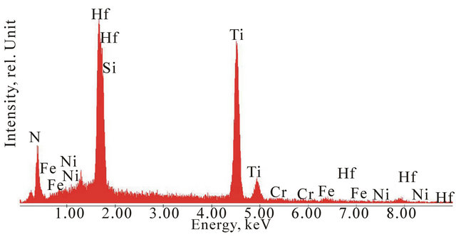 (b)
(b)
Figure 6. (а), (b) Energy disperse spectra of samples with Ti-Hf-Si-N coatings (Series 1): (a) integral information from area 2 × 2 mm; (b) local analysis.
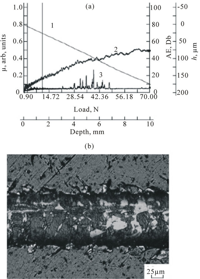
Figure 7. Results of adhesion tests of the Ti-Hf-Si-N coating/steel substrate system for the sample of series No. 23: (a) (1) the penetration depth h, (2) the friction coefficient µ, and (3) the acoustic emission (AE) and (b) structure of the coating in the fracture zone at loads in the range 0.9 - 90.0 N.
for the increase in local stresses and friction force. This leads to a rapid wear of the coating (Figure 7(b)).
In this work, two main critical loads were determined from the changes in the curves of the dependences of the friction coefficient and acoustic emission on the scribing load (Figure 7(a)). The first critical load corresponds to the onset of cohesive failure of the coating, whereas the second critical load corresponds to the plastic wear of the coating (adhesive failure). According to the results of adhesion tests, we can argue that the cohesive failure of the sample of series No. 23 occurs at a load of 2.38 N, and its adhesive failure, at a load of 9.81 N.
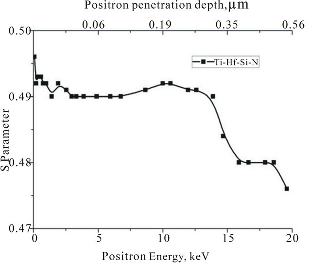
Figure 8 shows the dependence of S-parameters from energy of the incident positron micro beam. Presented profiles of vacancy-type defects in the coatings depth (Series 2 (a) and Series 3 (b)), significantly differ by stoichiometry (content) of elements, and by the phase composition (Figure 3). It is seen from the figure, where the behavior of the curves differ markedly, that in the case of samples series 2 we have a two-phase system consisting of a-Si3N4 and (Ti, Hf)N. Namely, a two-phase coating is characterized by two peaks (increase S-parameter) in the region of 10 keV and then in the region of 20 keV (near the coating-substrate interface). In the case of samples Series 3, we have a single-phase solid solution of (Ti, Hf)N and the S-parameter value is rather high –0.492 and
 (a)
(a)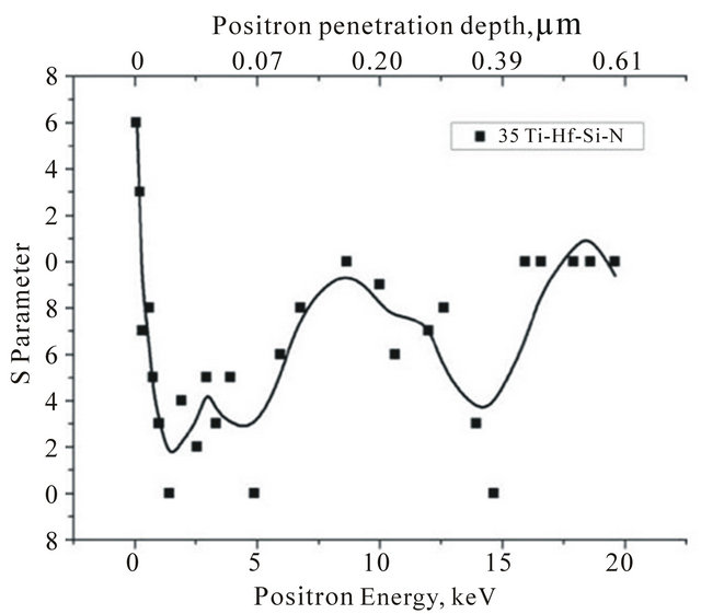 (b)
(b)
Figure 8. The dependence of S-parameter on incident positron microbeam energy of sample Series 2 (a) and Series 3 (b).
after reaching the film-substrate interface begins to decrease to value of 0.476 [9-12].
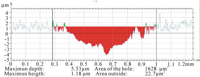
Figure 9(a)-(c) show the results of samples 23 (a), No 31 (b) and 35 (c) wear resistance tests. Based on the obtained data it can be argued that the coating of Series 23 (the smallest material removal, Figure 7(a)) with the lowest Hf content in solid solution (Ti, Hf)N (Table 1) has the greatest wear resistance. Accordingly, the degree of wear resistance decreases with increasing of Hf content in the solid solution (Figures 7(b) and (c)).
Destruction of the coating begins with the appearance of individual chevron cracks at the bottom of the wear groove, resulting in the increase of the local stress and friction. This leads to rapid subsequent abrasion of coating.
According to the results of adhesive tests of coating 23, cohesive destruction occurs at the minimum (critical)


(a) (b) (c)
Figures 9. (a)-(c) The results of wear resistance tests on the scratch tester REVETEST of samples No. 23 (a), No. 31 (b) and No. 35 (c).
load LC1 = 2.38 H, and adhesive destruction (plastic wear) comes with a load of the first crack appearance LC2 = 9.81 H.
The friction coefficient of the sample No 35 in the initial stage is 0.15, at the next stage, after 2.5 m of friction the coating is destroyed (potholes and cracks are appearing). The friction coefficient increases to 0.45, which confirms not very high hardness of the coating. In case of testing of the next coating sample No. 23 the friction coefficient increases up to 0.25 due to the high roughness of the coating, and when the steady depreciation stage is set, friction coefficient reaches the value of 0.2. A detailed study of parameters such as friction coefficient of, acoustic emission and penetration depth of the indenter, were performed for all samples [17-20].
4. Conclusions
New superhard nanostructured coatings (films) based on Ti-Hf-Si-N with high physical and mechanical characteristics and different stoichiome-tries (depending on the deposition conditions) have been fabricated. It has been found that a decrease in the size of nc-(Ti, Hf)N nanograins from 6.7 to 5.0 nm and the formation of the α-Si3N4 phase (in the form of an amorphous or quasiamorphous interlayer between the nanograins) result in an increase in the nanohard-ness from 42.7 to 48.4 ± 1.4 GPa. It has been established that, with an increase in the accelerating voltage to –200 V (separated and non-separated beams) during the deposition, the coatings with a smaller average crystallite size (up to 5.0 nm) are formed on the sub strate. An increase in the accelerating voltage from –100 to –200 V leads to the same value of the lattice parameter for both the textured and non-textured factions. In the case where the pressure decreases to 0.3 Pa, the relative content of Hf atoms in the coating increases and the average size of growing crystallites decreases.
Thus, the adhesion and tribological tests have made it possible to determine the adhesive strength, friction coefficient, and deformation characteristics of the Ti-HfSi-N coatings on the steel substrate. Based on measurements of different physical parameters during the adhesion tests, the processes of elastic and plastic deformations in the coating/substrate system have been described, and the threshold values of the critical load leading to different (cohesive and adhesive) types of failure of the coatings have been determined. The synthesized coatings have high values of the hardness, wear resistance, and adhesion to the substrate and low values of the modulus of elasticity and friction coefficient, which makes them promising thin-film materials for the use in mechanical engineering.
5. Acknowledgements
This work was supported by the Ministry of Education and Science, Youth and Sports of Ukraine in the frameworks of state program (Order No. 411), and in collaboration with the National Institute of Material Science, Tsukuba, Japan, Martin-Luther Universität Halle-Wittenberg, Ion Beam Center FWIZ, Dresden, the project FRSF-041/20, Ukraine, and partly by the research project 011U001382 “Designing of the basis of formation of multicomponent nanostructured superhard coatings with high physical and mechanical properties”. We are grateful to Prof. O. V. Sobol (Kharkiv National Technical University (KPI)), Prof. V. V. Uglov (Belarusian State University), Dr. G. Abrasonis (Helmholtz Zentrum Dresden Rossendorf, ION Beam Center FWIZ, Dresden, Germany) for help with the experiments.
REFERENCES
- R. F. Zhang, A. S. Argon and S. Veprek, “Electronic Structure, Stability, and Mechanism of the Decohesion and Shear of Interfaces in Superhard Nanocomposites and Heterostructures,” Physical Review B, Vol. 79, No. 24 2009, pp. 245-426. doi:10.1103/PhysRevB.79.245426
- J. Musil, J. Vlcek and P. Zeman, “Hard Amorphous Nanocomposite Coatings with Oxidation Resistance above 1000˚C,” Advances in Applied Ceramics, Vol. 107, No. 3, 2008, pp. 148-154. doi:10.1179/174367508X306460
- A. D. Pogrebnjak, A. P. Shpak, N. A. Azarenkov and V. M. Beresnev, “Structures and Properties of Hard and Superhard Nanocomposite Coatings,” Physics-Uspekhi, Vol. 52, No. 1, 2009, pp. 29-54. doi:10.3367/UFNe.0179.200901b.0035
- A. D. Pogrebnjak, A. G. Ponomarev, A. P. Shpak and Yu. A. Kunitskii, “Application of Microand Nanoprobes to the Analysis of Small-Sized 3D Materials, Nanosystems, and Nanoobjects,” Physics-Uspekhi, Vol. 55, No. 3, 2012, pp. 270-300. doi:10.3367/UFNe.0182.201203d.0287
- A. D. Pogrebnjak, O. V. Sobol, V. M. Beresnev, P. V. Turbin, G. V. Kirik, N. A. Makhmudov, M. V. Il’yashenko, A. P. Shypylenko, M. V. Kaverin, M. Yu. Tashmetov and A. V. Pshyk, “Phase Composition, Thermal Stability, Physical and Mechanical Properties of Superhard on Base Zr-Ti-Si-N Nanocomposite Coatings,” Nanostructured Materials and Nanotechnology IV: Ceramic Engineering and Science Proceedings, Vol. 31, No. 7, 2010, pp.127-138.
- A. D. Pogrebnyak, A. G. Ponomarev, D. A. Kolesnikov, V. M. Beresnev, F. F. Komarov, S. S. Mel’nik, and M. V. Kaverin, “Effect of Mass Transfer and Segregation on the Formation of Superhard Nanostructured Ti-Hf-N(Fe) Coatings,” Technical Physics Letters, Vol. 38, No. 7, 2012, pp. 623-626. doi:10.1134/S1063785012070103
- W. F. Gale and T. C. Totemeier, “Smithells Metals Reference Book,” Butterworth Heinemann, Oxford, 1976; Metallurgiya, Moscow, 1980.
- R. Krause-Rehberg and H. S. Leipner, “Positron Annihilation in Semiconductors,” Springer Verlag, Berlin, 1999, p. 378. doi:10.1007/978-3-662-03893-2
- V. I. Grafutin, O. V. Ilyukhina, G. G. Myasishcheva, E. P. Prokopiev, S. P. Timoshenkov, Y. V. Funtikov and R. Burcl, “Positronics and Nanotechnologies: Possibilities of Studying Nanoobjects in Materials and Nanomaterials by the Method of Positron-Annihilation Spectroscopy,” Physics of Atomic Nuclei, Vol. 72, No. 10, 2009, pp. 1672- 1681. doi:10.1134/S1063778809100081
- J. Kansy, “Programs for Positron Lifetime Analysis Adjusted to the PC Windows Environment,” Materials Science Forum, Vol. 652, 2001, pp. 363-365.
- V. I. Grafutin and E. P. Prokop’ev, “Positron Annihilation Spectroscopy in Materials Structure Studies,” PhysicsUspekhi, Vol. 45, No. 1, 2002, pp. 59-74. doi:10.1070/PU2002v045n01ABEH000971
- P. Konarski, I. Iwanejko, A. Mierzejewska and R. Diduszko, “Morphology of Working Environment Microparticles,” Vacuum, Vol. 63, No. 4, 2001, pp. 679-683. doi:10.1016/S0042-207X(01)00257-3
- P. Konarski, I. Iwanejko and A. Mierzejewska, “SIMS Depth Profiling of Working Environment Nanoparticles,” Applied Surface Science, Vol. 203-204, 2003, pp. 757- 761. doi:10.1016/S0169-4332(02)00881-4
- A. D. Pogrebnjak, V. M. Beresnev, A. A. Demianenko, V. S. Baidak, F. F. Komarov, M. V. Kaverin, N. A. Makhmudov and D. A. Kolesnikov, “Adhesive Strength, Superhardness, and the Phase and Elemental Compositions of Nanostructured Coatings Based on Ti-Hf-Si-N,” Physics of the Solid State (Russian), Vol. 54, No. 9, 2012, pp. 1882-1890.
- A. D. Pogrebnyak, A. P. Shpak, V. M. Beresnev, G. V. Kirik, D. A. Kolesnikov, F. F. Komarov, P. Konarski, N. A. Makhmudov, M. V. Kaverin and V. V. Grudnitskii, “Stoichiometry, Phase Composition, and Properties of Superhard Nanostructured Ti-Hf-Si-N Coatings Obtained by Deposition from High Frequency Vacuum-Arc Discharge,” Technical Physics Letters (Russian), Vol. 37, No. 7, 2011, pp. 636-640.
- A. D. Pogrebnjak, M. Danilionok, V. V. Uglov, N. K. Erdybaeva, G. V. Kirik, V. S. Rusakov, A. P. Shypylenko, P. V. Zukovski and Yu. Zh. Tuleushev, “Nanocomposite Protective Coatings on Ti-N-Cr/Ni-Cr-B-Si-Fe, Their Structure and Properties,” Vacuum, Vol. 83, Suppl. 1, 2009, p. 235-239. doi:10.1016/j.vacuum.2009.01.071
- A. V. Khomenko and I. A. Lyashenko, “A Stochastic Model of Stick-Slip Boundary Friction with Account for the Deformation Effect of the Shear Modulus of the Lubricant,” Journal of Friction and Wear, Vol. 31, No. 4, 2010, pp. 308-316. doi:10.3103/S1068366610040100
- P. Misaelides, A. Hadzidimitrion, F. Noli, E. Pavlidou and A. D. Pogrebnjak, “Investigation of the Characteristics and Corrosion Resistance of Al2O3/TiN Coatings,” Applied Surface Science, Vol. 252, No. 23, 2006, pp. 8043- 8049. doi:10.1016/j.apsusc.2005.09.075
- A. D. Pogrebnyak, O. V. Sobol’, V. M. Beresnev, P. V. Turbin, S. N. Dub, G. V. Kirik and A. E. Dmitrienko, “Features of the Structural State and Mechanical Properties of ZrN and Zr(Ti)-Si-N Coatings Obtained by Ion-Plasma Deposition Technique,” Technical Physics Letters, Vol. 35, No. 10, 2009, pp. 925-928. doi:10.1134/S1063785009100150
- A. D. Pogrebnjak, Sh. M. Ruzimov, D. L. Alontseva, P. Żukowski, C. Karwat, C. Kozak and M. Kolasik, “Structure and Properties of Coatings on Ni Base Deposited Using a Plasma Jet before and after Electron a Beam Irradiation,” Vacuum, Vol. 81, No. 10, 2007, pp. 1243-1251. doi:10.1016/j.vacuum.2007.01.071
- A. D. Pogrebnyak, M. M. Danilenok, A. A. Drobyshevskaya, V. M. Beresnev, N. K. Erdybaeva, G. V. Kirik, S. N. Dub, V. S. Rusakov, V. V. Uglov, A. P. Shipilenko and Yu. Zh. Tuleushev, “Investigation of the Structure and Physicochemical Properties of Combined Nanocomposite Coatings Based on Ti-N-Cr/Ni-Cr-B-Si-Fe,” Russian Physics Journal, Vol. 52, No. 12, 2009, pp. 1317- 1324. doi:10.1007/s11182-010-9378-1
- http://www.iso.org
- R. A. Andrievskii, G. V. Kalinnikov, N. Hellgren, P. Sandstrom and D. V. Shtanskii, “Nanoindentation and Strain Characteristics of Nanostructured Boride/Nitride Films,” Physics of the Solid State, Vol. 42, No. 9, 2000, pp. 1671- 1674. doi:10.1134/1.1309449