Materials Sciences and Applications
Vol.5 No.4(2014), Article ID:44151,6 pages DOI:10.4236/msa.2014.54024
Synthesis of Zirconia Oxide (ZrO2) Nanofibers on Zirconnia Substrates by Ultrasonic Spray Pyrolysis
Jianhui Zhang1,2*, Wei Li3, Takayoshi Tanji1,2
1EcoTopia Science Institute, Nagoya University, Nagoya, Japan
2Global Research Center for Environment and Energy Based on Nanomaterials Science, Nagoya, Japan
3Graduate School of Engineering, Nagoya, Japan
Email: *zhangjianhuijp@yahoo.co.jp
Copyright © 2014 by authors and Scientific Research Publishing Inc.
This work is licensed under the Creative Commons Attribution International License (CC BY).
http://creativecommons.org/licenses/by/4.0/


Received 31 December 2013; revised 6 February 2014; accepted 27 February 2014
ABSTRACT
Zirconia oxide (ZrO2) nanofibers were synthesized using Phosphorus/water mixture as catalyst by ultrasonic spray pyrolysis CVD on the zirconia substrate at 900˚C for 1 h in N2 gas. Scanning electron microscopy (SEM) and high-resolution transmission electron microscopy (HRTEM) examinations show that all the synthesized nanofibers have uniform surface morphology and their diameters are in the range of 100 nm. The HRTEM selected-area electron diffraction pattern (SAED) shows that crystalline ZrO2 phase exist in the nanofibers, and the energy-dispersive x-ray spectroscopy (EDS) results show that the elements of Zr and O are uniformly distributed across the nanofiber matrix. The phosphorus atoms corroded the entire Zirconia substrate surface, and the Zirconia-Phosphorus liquid-catalyzed the solid-liquid-solid mechanism is proposed to explain the growth of the nanofibers.
Keywords:Nanofibers; Chemical Vapor Deposition; EDS

1. Introduction
In recent years, the many important works are then published in which a chemical vapor deposition (CVD) is introduced and successfully synthesized in the nanofibers or nanorods of ZnO [1] , SnO2 [2] , CaN [3] , TiO2 [4] and Bi2O3 [5] etc. They are a type of one-dimensional (1-D) nano-structural materials exhibit novel physical properties in a number of areas [6] . They have been widely studied due to the great potential applications in electronic properties [7] , and excellent optical properties [8] . Among which the ZrO2 nanofibers have a high aspect ratio and a high specific surface area, the nanofibers have been extensively applied in excellent thermal and chemical stability, high strength and fracture toughness, low thermal conductivity, high corrosion resistance, because of its technical importance and broad practical applications, such as thermal barrier coatings [9] , solid oxide fuel cells [10] , various sensors [11] , gate dielectrics [12] , catalysts [13] , ceramic biomaterial [14] , metallic glass [15] . Several methods have been used to synthesize ZrO2 nanofibers, including ionic-liquid route [16] , a modified sol-gel method [6] , electrospinning [17] . However, there have been no reports on the ZrO2 nanofibers using CVD method.
In the present study, we have obtained nanofibers that have diameter of about 100 nm with using phosphorus/water mixture as catalyst. This method produces mist of phosphorus/water mixture by ultrasonic spray pyrolysis for the synthesis of nanofibers. A possible growth mechanism of such ZrO2 nanofibers is also discussed in the present study, e.g. the growth of such nanofibers is attributed to solid-liquid-solid (SLS) growth mechanism [18] . This is the promising method to grow ZrO2-nanofibers.
2. Experimental
Details of the present method have been reported previously as shown in Figure 1 [18] . A zirconia substrate was used as a substrate and the mixture of phosphorus/water or water was used as corrosive source. The reactor furnace was heated to the range of 700˚C - 1000˚C in N2 flow, the phosphorus mixed with the water or only water was placed inside the atomization chamber of the ultrasonic spray pyrolysis machine [19] . The synthesis was in N2 gas atmosphere. In the present study, phosphorus (Kojundo Chemical Laboratory; 99%) was used. Produced samples were analyzed using a scanning electron microscope (SEM), a transmission electron microscope (TEM), as well as energy dispersive spectrum (EDS).
3. Results and Discussion
Figure 2(a) shows SEM image of ZrO2 nanofibers that were synthesized on the zirconia substrate at 900˚C for 1 h, they were uniform and their diameter was about 100 nm, disordered vertically condition. We found that the present an individual nanofiber having a diameter of about 100 nm, a black spot on the tip of nanofiber by the TEM observations which is shown in Figures 2(b) and (c). The TEM observation indicates that the present bulky bottom of nanofiber as shown in Figure 2(d), it indicated that the nanofibers of growth from the zirconia substrate. We also observed a black spot at the tip of nanofiber. Figure 2(e) shows the EDS spectrum of the tip (spot (i)) of nanofiber shows three distinct peaks of Cu, O and Zr, with the Cu peak possibly coming partially from the TEM grid. However, we did not find any phosphorus in the tip of nanofiber within the detection limits.
The short and sparse nanofibers was observed in the sample synthesized at 700˚C as shown in Figure 3(a). The yield of nanofibers can be synthesized at 800˚C, the length of nanofibers nearly did not change as shown in Figure 3(b). Straight and longer nanofibers yield were observed in the sample synthesized at 900˚C as shown in Figure 3(c). At 1000˚C, the density of nanofibers became sparse again, and the aggregation of the bottom of nanofibers originated from the surface of zirconia substrate. According to above these SEM images, we expected that the growth temperature can affect the synthesis of nanofibers. The amounts of active zirconia/phosphorus
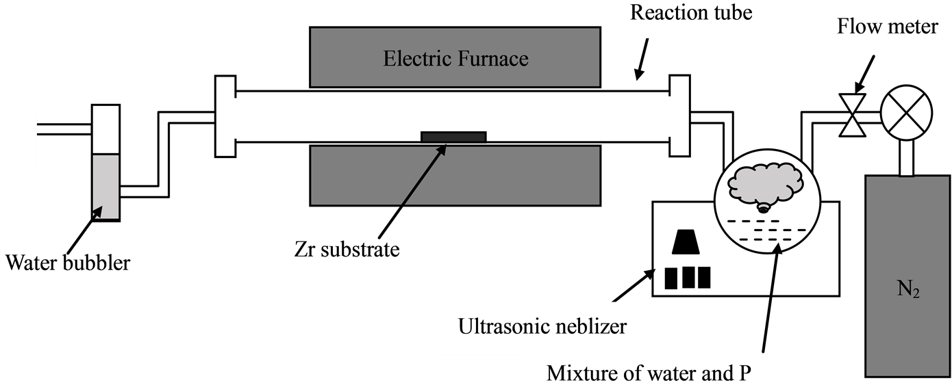
Figure 1. Schematic image of the apparatus of the spray pyrolysis CVD.
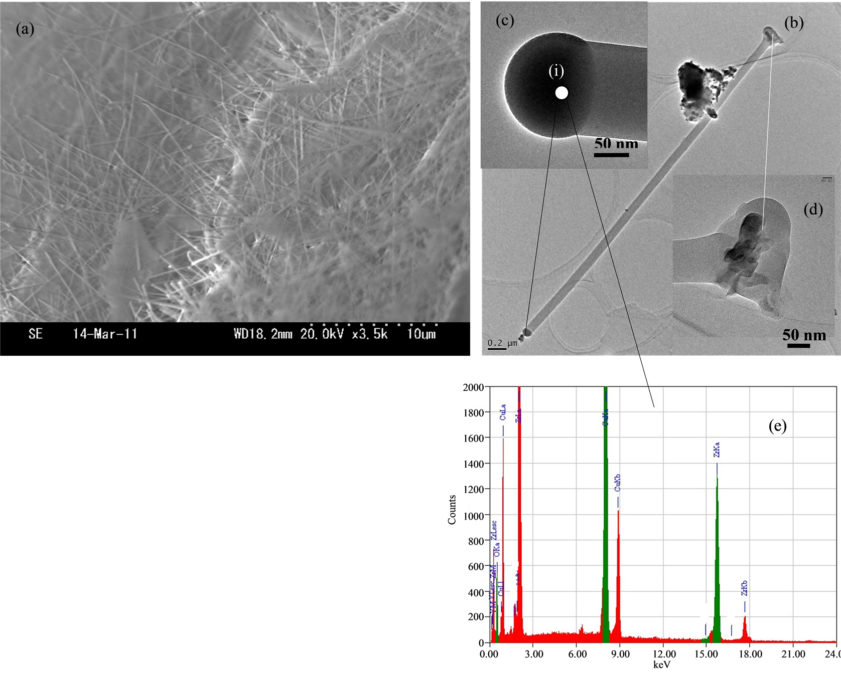
Figure 2. SEM images of ZrO2 nanofibers on Zr substrate synthesized at 850˚C. (a) SEM image of nanofibers; (b) TEM image of nanofiber; (c) The TEM image of nanofiber tip; (d) The TEM image of nanofiber bottom; and (e) The EDS of nanofiber tip.
mixture increase with increasing growth temperature. However, the aggregation of the bottom of nanofibers are prompted by higher temperature heating, as shown in Figure 3(d). It is worth pointing out that the calcination at 900˚C resulted in some substantial the ZrO2 nanofibers morphology as compared to synthesis at 700˚C, 800˚C, 1000˚C.
Figure 4(a) shows a TEM image of nanofiber body, many little particles were adsorbed on the surface of the body, due to evaporation of the polymer and the crystallization of ZrO2, that was composed of nanocrystalline grains <5 nm in size. The inset shows the electron diffraction pattern of selected area. The rings were indexed as the (111), (200), (220) and (311) lattice planes as shown in Figure 4(b). Figure 4(c) shows the EDS of the body (spot (ii)) of the nanofiber. The Cu, Zr and oxygen elements are detected, respectively. The Cu peak results from the Cu parts of the measurement chamber and the Zr and O peaks comes from the body of nanofiber. However, we found that the phosphorus element cannot existed in the nanofibers, and we estimated that flow N2 gas can carry phosphorus element away from the nanofibers owing to the high temperature.
Figure 5 is a schematic illustration of the growth mechanism. It involved in the formation of the ZrO2-nanofiber are proposed as follows. Initially, the phosphorus coating on the zirconia substrate forms a thin phosphrous film, as illustrate in Figure 5(a). When the reaction temperature increases, the zirconia substrate is oxidized in the carrier N2 and by the water. A reaction between the Zr and P occur form a thin Zr-P eutectic liquid layer, as illustrated in Figure 5(b). Because the melting point of Zr is 1855˚C, a temperature at which the Zr vapor phase is negligible, and the Zr substrate itself serves as an Zr source without and additional external Zr source, the nanofibers should be formed via a solid-liquid-solid (SLS) mechanism. Finally, the surface of the Zr-P eutectic liquid soon becomes supersaturated, and appeared the aggregating into ZrO2-nanoparticles condition via heating as shown in Figure 5(c). And then the nanofibers precipitate out and continue to grow from ZrO2-nanopaticles (saturation nucleation) of this supersaturated surface as illustrate in Figure 5(d), possibly through the oxidation
 (a)
(a)  (b)
(b)  (c)
(c)  (d)
(d)
Figure 3.SEM images of nanofibers synthesized from different temperatures: (a) 650˚C; (b) 750˚C; (c) 850˚C; (d) 950˚C.
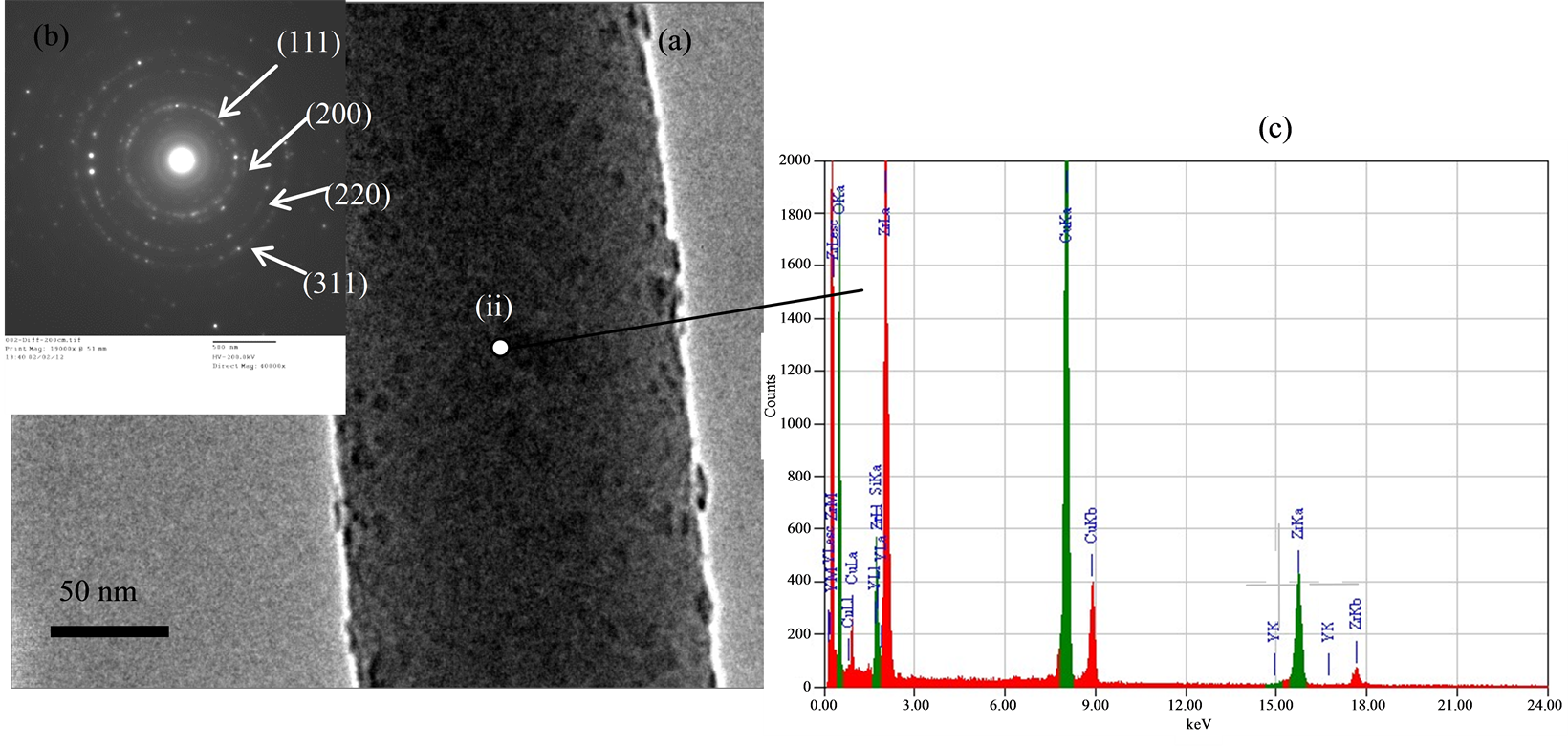
Figure 4. (a) TEM images of nanofiber body; (b) EDS spectrum of TEM image of a nanofiber; (c) EDS of nanofiber.
reactions of Zr + 2H2O → ZrO2 + 2H2.
4. Conclusion
In the present study, we successfully synthesized the nanofibers with a mixture of phosphorus/water on a Zr substrate using ultrasonic spray pyrolysis method. The ZrO2 nanofibers were produced on the surface of the Zr
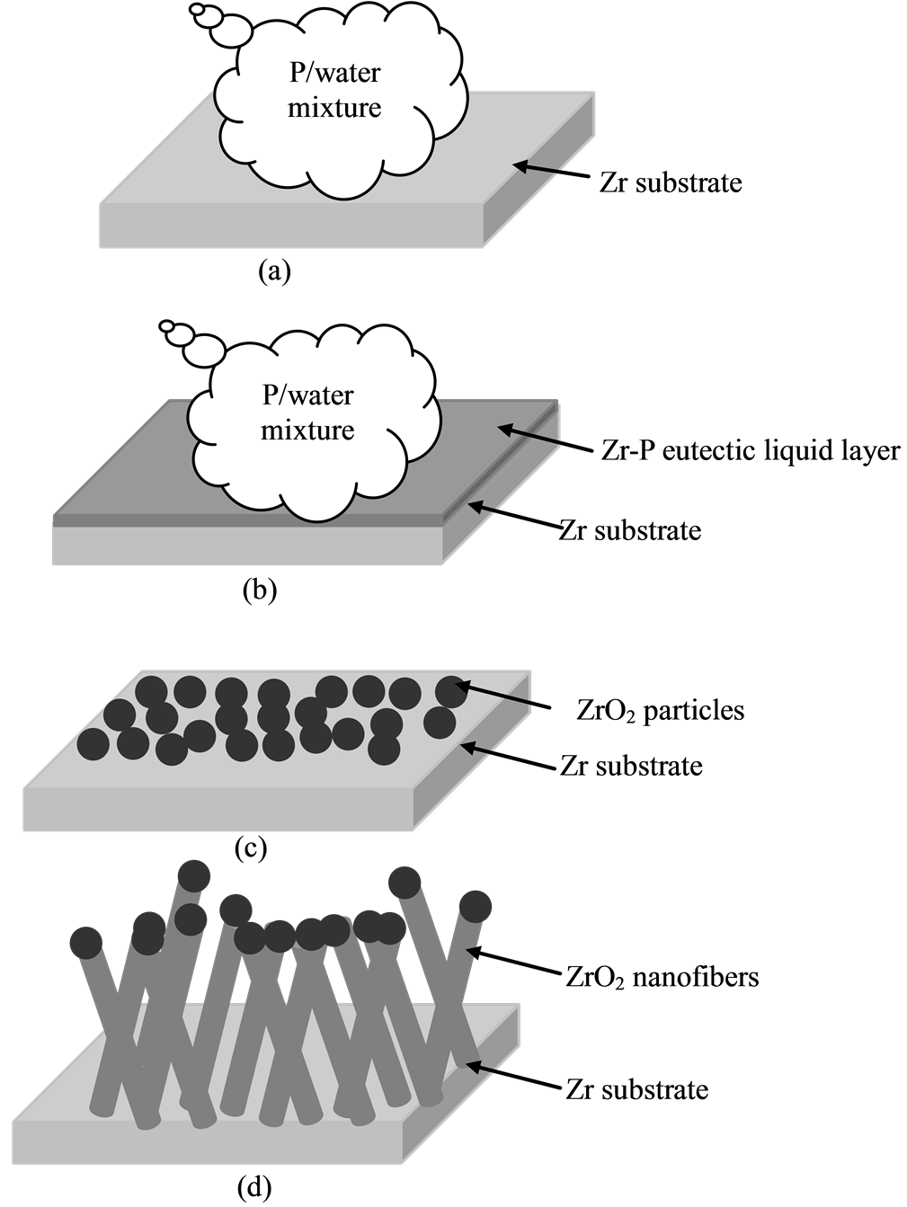
Figure 5. Schematic illustration of the growth processes.
substrate, and the mixture of Zr/phosphorus eutectic liquid layer thereafter the synthesized nanoparticles on Zr substrate played a key role in determining the growth model of nanofibers. A possible mechanism for this process is the formation of the nanofibers from the surface the Zr-P liquid layer. We believed that this approach to the synthesis of nanofibers may be further used in the fabrication of fuel cells and oxygen sensors.
References
- Jeong, M., Oh, B., Lee, W. and Myoung, J. (2004) Comparative Study on the Characteristics of ZnO Nanowire and Thin Films by Metalorganic Chemical Vapor Deposition (MOCVD). Journal of Crystal Growth, 268, 149-154. http://dx.doi.org/10.1016/j.jcrysgro.2004.05.019
- Yin, W., Wei, B. and Hu, C. (2009) In Situ Growth of SnO2 Nanowires on the Surface of Au-Coated Sn Grains Using Water-Assisted Chemical Vapor Deposition. Chemical Physics Letters, 471, 11-16. http://dx.doi.org/10.1016/j.cplett.2009.02.021
- Wei, X. and Shi, F. (2011) Synthesis and Characterization of GaN Nanowires by a Catalyst Assisted Chemical Vapor Deposition. Applied Surface Science, 257, 9931-9934. http://dx.doi.org/10.1016/j.apsusc.2011.06.110
- Pradhan, S.K., Reucroft, P.J., Yang, F. and Dozier, A. (2003) Growth of TiO2 Nanorods by Metalorganic Chemical Vapor Deposition. Journal of Crystal Growth, 256, 83-88. http://dx.doi.org/10.1016/S0022-0248(03)01339-3
- Kim, H.W., Lee, J.W. and Shim, S.H. (2007) Study of Bi2O3 Nanorods Grown Using the MOCVD Technique. Sensors and Actuators B: Chemical, 126, 306-310. http://dx.doi.org/10.1016/j.snb.2007.01.002
- Pavasupree, S., Suzuki, Y., Pivsa-Art, S. and Yoshikawa, S. (2005) Synthesis and Characterization of Nanoporous, Nanorods, Nanowires Metal Oxide. Science and Technology of Advanced Materials, 6, 224-229. http://dx.doi.org/10.1016/j.stam.2005.02.001
- Bayat, M., Yang, H. and Ko, F. (2011) Electromagnetic Properties of Electrospun Fe3O4/Carbon Composite Nanofibers. Polymer, 52, 1645-1653. http://dx.doi.org/10.1016/j.polymer.2011.01.057
- Tong, L., Zi, F., Guo, X. and Lou, J. (2012) Optical Microfibers and Nanofibers: A Tutorial. Optics Communications, 285, 4641-4647. http://dx.doi.org/10.1016/j.optcom.2012.07.068
- Thurm, G., Schneider, G.A., Bahr, H.A. and Aldinger, F. (2000) Toughness Anisotropy and Damage Behavior of Plasma Sprayed ZrO2 Thermal Barrier Coatings. Surface and Coatings Technology, 123, 147-158. http://dx.doi.org/10.1016/S0257-8972(99)00528-9
- Sekcuk, A. and Atkison, A. (1997) Elastic Properties of Ceramic Oxides Used in Solid Oxide Fuel Cells. Journal of the European Ceramic Society, 17, 1523-1532. http://dx.doi.org/10.1016/S0955-2219(96)00247-6
- Zhang, R., Zhang, X. and Hu, S. (2006) Nanocrystalline ZrO2 Thin Films as Electrode Materials Using in High Temperature-Pressure Chemical Sensors. Materials Letters, 60, 3170-3174. http://dx.doi.org/10.1016/j.matlet.2006.02.080
- Maiti, C.K., Dalapati, G.K., Chatterjee, S., Samanta, S.K., Varma, S. and Patil, S. (2004) Electrical Properties of High Permittivity ZrO2 Gate Dielectrics on Strained-Si. Solid-State Electronics, 48, 2235-2241. http://dx.doi.org/10.1016/j.sse.2004.04.012
- Zheng, W.T., Sun, K.Q., Liu, H.M., Liang, Y. and Xu, B.Q. (2012) Nanocomposite Ni/ZrO2: Highly Active and Stable Catalyst for H2 Production via Cyclic Stepwise Methane Reforming Reactions. International Journal of Hydrogen Energy, 37, 11735-11747. http://dx.doi.org/10.1016/j.ijhydene.2012.05.099
- Pandey, A.K. and Biswas, K. (2011) Influence of Sintering Parameters on Tribological Properties of Ceria Stabilized Zirconia Bio-Ceramics. Ceramics International, 37, 257-264. http://dx.doi.org/10.1016/j.ceramint.2010.08.041
- Huang, L., Cao, Z., Meyer, H.M., Liaw, P.K., Garlea, E., Dunlap, J.R., Zhang, T. and He, W. (2011) Responses of Bone-Form Cells on Pre-Immersed Zr-Base Bulk Metallic Glasses: Effect of Composition and Roughness. Acta Biomaterialia, 7, 395-405. http://dx.doi.org/10.1016/j.actbio.2010.08.002
- Dong, W., Lin, F., Liu, C. and Li, M. (2009) Synthesis of ZrO2 Nanowires by Ionic-Liquid Route. Journal of Colloid and Interface Science, 333, 734-740. http://dx.doi.org/10.1016/j.jcis.2009.02.025
- Formo, E., Camargo, P.H.C., Lim, B., Jiang, M. and Xia, Y. (2009) Functionalization of ZrO2 Nanofibers with Pt Nanostructures: The Effect of Surface Roughness on Nucleation Mechanism and Morphology Control. Chemical Physics Letters, 476, 56-61. http://dx.doi.org/10.1016/j.cplett.2009.05.075
- Wagner, R.S. and Ellis, W.C. (1964) Vapor-Liquid-Solid Mechanism of Single Crystal Growth. Applied Physics Letters, 4, 89-90. http://dx.doi.org/10.1063/1.1753975
NOTES

*Corresponding author.