Materials Sciences and Applications
Vol.3 No.8(2012), Article ID:21793,7 pages DOI:10.4236/msa.2012.38074
Comparison of Silicon Nitride Nanofibers Synthesized Using Silica Nanopowders and Silica Gel
![]()
Mechanical Engineering Department, Villanova University, Villanova, USA.
Email: sridhar.santhanam@villanova.edu
Received May 9th, 2012; revised June 10th, 2012; accepted July 10th, 2012
Keywords: silicon nitride; nanofibers; carbothermal
ABSTRACT
Nanofibers of alpha silicon nitride were grown by a vapor-solid mechanism at 1450˚C, through the carbothermal reduction process. Two different precursor silica sources were used: silica nanopowders and silica gel. The effect of processing geometry, particularly the stacking orientations of the graphite substrates, silica pellets, and crucibles, on the density of nanofiber growth was also explored. The silicon nitride nanofibers appear with a predominantly rectangular cross section from silica nanopowder precursors and with a circular cross section for silica gel precursors. Silica gel precursors produce nanofiber products that are smaller in cross section but greater in length than the products from silica nanopowder precursors. The processing geometry must be suitably designed such that the vapor-solid mechanism that is responsible for the formation of the nanofibers is not disrupted.
1. Introduction
One dimensional nanoscale structures of oxide and nonoxide ceramics have been a subject of much research in the recent past [1-4]. In particular, the fabrication of one dimensional nanowires, nanorods, and nanofibers of ceramics such as silicon nitride has been investigated intensively [5-16]. Silicon nitride has many attractive properties including high strength, hardness, and resistance to thermal shock and oxidation. It has excellent chemical stability and creep resistance at high temperatures. Silicon nitride also has a wide band gap and other useful optical properties that make it suitable for applications in microelectronics and optics. One dimensional nanoscale structures of silicon nitride offer promise for applications in optics, semiconductors, and for strengthening and toughening materials.
One dimensional structures of silicon nitride including nanorods, nanowires, and nanofibers have been fabricated through several routes. Kim et al. [17] utilized a method of synthesizing silicon nitride nanowires directly from silicon substrates. Gallium, gallium nitride, and/or iron nanoparticles were used as catalysts on the silicon substrate. Dense nanowires were seen to grow from the substrate at a temperature of 1200˚C under ammonia or hydrogen flow. Bechelany et al. [15] prepared silicon nitride nanorods from beta silicon carbide nanowire precursors. Silicon carbide nanowires were thermally treated at 1400˚C in an ammonia atmosphere causing their conversion to silicon nitride nanorods. Han et al. [18] used carbon nanotubes as templates for the synthesis of silicon nitride nanorods. A silicon-silica powder mixture was used as the source of silicon. At a temperature of 1400˚C, in a flowing nitrogen gas atmosphere, a white wool-like layer of beta silicon nitride was observed. Zou et al. [19] presented a low temperature method of synthesis involving the reaction between Mg3Cl2 and SiCl4 at 600˚C. Alpha silicon nitride nanowires formed with a fairly high purity. Another route to successful synthesis was outlined by Zhang et al. [20]. They used the direct crystallization of amorphous silicon nitride nanopowders under high temperature in a flowing nitrogen atmosphere. Recently, Ren et al. [21] used a mechanosynthesis process to make silicon nitride nanowires.
In this work, we have utilized carbothermal reduction to produce silicon nitride nanofibers. This is a wellknown route. For instance, Zhang et al. [11] produced silicon nitride single crystal nanowires using carbothermal reduction. They created an intimate mixture of a silica xerogel and carbon nanoparticles using a sol-gel process. This was followed by a reduction process in a nitrogen atmosphere. A similar approach was taken by Arik [9]. Diatomite, used as the source of silica, and carbon black mixtures were subjected to the carbothermal reduction process in an atmosphere of nitrogen, thereby producing both alpha and beta silicon nitride fibrous products. Wu et al. [10] produced silicon nitride and silicon carbide nanorods by calcining pellets of silica nanoparticles with active carbon at 1450˚C in a flowing nitrogen atmosphere.
Our objectives in this work were twofold. The first objective was to examine the effect of the precursor silica source on the morphology and nature of the silicon nitride nanofibers. A second objective was to study if the density of the silicon nitride nanofiber growth was affected by the geometry and orientation of the substrates on which these nanofibers grew. Silica nanopowders and silica gel were both used separately as the source of silica. Activated charcoal was used as the carbon source. Graphite plates were used as substrates for the growth of the nanofibers. The processing involved to produce the silicon nitride fibers was unchanged between the two precursors. Several interesting differences in the morphology of the fibers were found.
2. Experimental Procedure
The precursor silica sources were either silica gel (Davisil grade 643, pore size 150 Angstroms, 200 - 425 mesh, Sigma Aldrich) or silica nanopowders (10 - 20 nm (TEM), 99.5% trace metals basis, Sigma Aldrich). The silica precursor powder and activated charcoal were mixed, with a mass ratio of 10:1, in a methanol solution. The liquid suspension was then placed in a plastic bottle for ball milling for 15 minutes. About 20 silicon nitride balls were added to the suspension for ball milling. Then the solution was dried at 100˚C overnight in an oven. Next, the powder mixtures were mixed with Poly Vinyl Alcohol (PVA, Elvanol, 71 - 30, Chemicalstore.com) binder and molded into raw pellets (25 mm diameter) using a cold press. The raw pellets were dried overnight. After drying, the raw pellets were interlaced with graphite plates and placed in a cylindrical graphite crucible. The graphite plates were of the same diameter as the pellets (25 mm) and about the same thickness (5 mm). The cylindrical graphite crucible was then placed in the center of a horizontal alumina tube furnace (CM Furnace Model 1730-12HT). After replacing the air with high purity N2, the graphite crucible was heated to 1450˚C in 8 hours and kept at that temperature for another 6 hours. The furnace was cooled down to room temperature in 8 hours. Nitrogen gas was streamed through the alumina tube furnace at a rate of 20 sccm (standard cubic centimeters per minute) during the entire heating and cooling cycle.
Three different stacking configurations of the powder pellets and the graphite plates were considered. These are shown in Figures 1 and 2. Figure 1 shows the first two arrangements. In arrangement 1 on the left, the graphite crucible is laid down horizontally in the horizontal tube furnace with a vertical arrangement of alternating raw
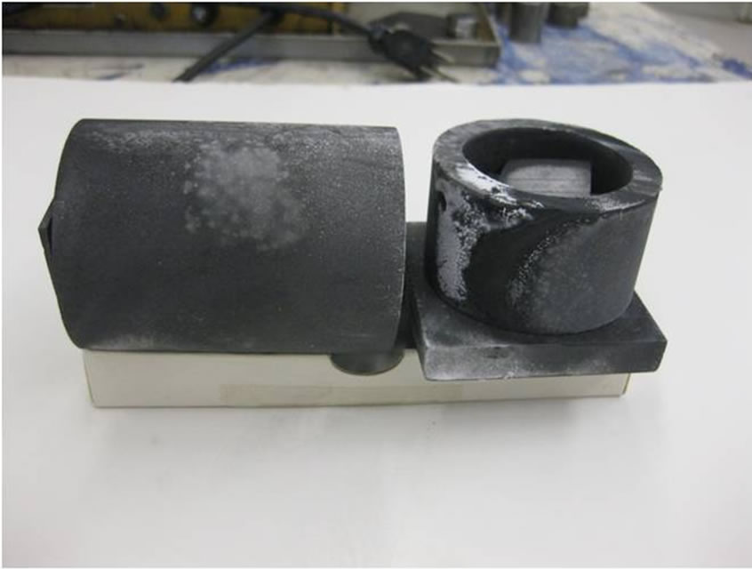
Figure 1. Graphite crucible placed in two configurations: horizontal and vertical. The horizontal crucible (left) has a stack of alternating raw pellets and graphite plates arranged vertically (arrangement 1). The vertical crucible (right) has a stack of alternating raw pellets and graphite plates arranged horizontally (arrangement 2).
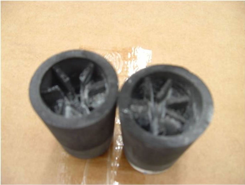
Figure 2. Graphite crucible in a vertical configuration. The crucible has a stack of alternating raw pellets and graphite plates arranged vertically (arrangement 3).
pellets and graphite plates. The pellets and graphite plates are oriented vertically. In arrangement 2 on the right (Figure 1), the crucible is placed vertically in the horizontal tube furnace and has a horizontal alternate stacked arrangement of raw pellets and graphite plates. In arrangement 3, shown in Figure 2, the graphite crucible is placed vertically inside the tube furnace, with the alternate stack of raw pellets and horizontal tube furnace, with the alternate stack of raw pellets and graphite plates vertical in orientation. These different arrangements were considered with the aim of ascertaining the effect of the flow and dwell of Nitrogen gas over the raw pellets on the nature and density of the growth of the nanofibers.
The silicon nitride nanofiber products were observed on the surfaces of the pellets, graphite plates, and the crucible walls. The products were characterized as described in the next section.
3. Results and Discussion
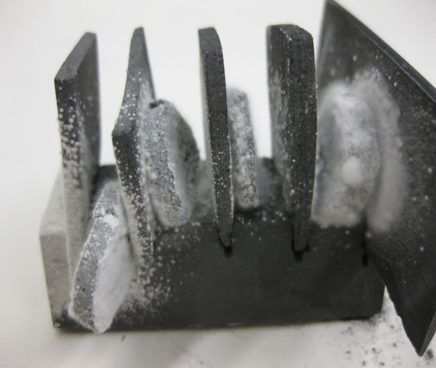
Figure 3 shows the growth of nanofibers from the silica nanopowder precursors. Figure 3(a) shows the growth of the nanofibers in arrangement 1 while Figure 3(b) shows the growth in arrangement 3. Evidently, growth is seen on both the graphite plate substrates and the raw pellets. The density of growth is higher on the graphite plates when compared with the raw pellets. In arrangement 1, where the crucible is horizontal, the nanofibers grow uniformly over most surfaces on the vertical graphite plates/substrates. In arrangement 3, where the crucible is vertical, the density of growth is higher at the bottom of the crucible. In some regions, the dense clusters of nanofibers form a cottonball shape.
Figure 4 shows formation of dense clusters of nanofibers from silica gel precursor pellets using arrangement 3. Trends observed in the manner of growth of nanofibers in silica nanopowder pellets were seen in silica gel pellets as well. One important difference was that a preferential dense growth was seen for the latter on the surface of the pellets with the growth somewhat muted on the surface of the graphite plates. For both precursors, arrangements 1 and 3 provided greater yields of the nanofiber products than arrangement 2. This was a result of the greater exposed surface area of the raw pellets and the graphite plate substrates to the flow of N2. In both
 (a)
(a) (b)
(b)
Figure 3. Growth of silicon nitride nanofibers from silica nanopowder precursor in arrangements (a) 1 and (b) 3.
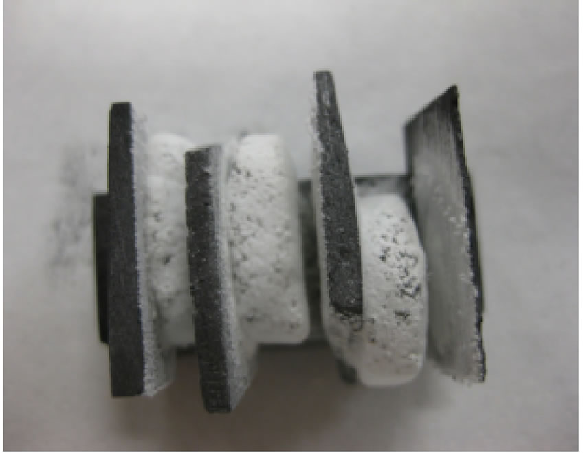
Figure 4. Growth of silicon nitride nanofibers from silica gel precursor in arrangement 3.
arrangements 1 and 3, the raw silica pellets and the graphite plate substrates are in very close proximity, but not in intimate contact, thus allowing the flow of N2 gas over their surfaces. On the other hand, in arrangement 2, the pellets and the plates are horizontally stacked on top of each other, thereby reducing the exposed surface area to N2 gas. In arrangement 3, the majority of the fibers grew in the bottom of the crucible.
The morphology of the nanofibers was characterized using High Resolution Scanning Electron Microscopy (Hitachi S-4800). Figure 5 shows nanofibers grown on the graphite plate substrate from a silica nanopowder precursor. The fibers are several tens of microns long, with some reaching a length of 100 microns or more.
On closer examination many of the nanofibers formed from the silica nanopowder precursor have an almost rectangular cross section (Figure 6). Some fibers show interesting growth patterns such as kinks (Figure 6), branches, and cross configurations. Fibers invariably did not show a rounded tip, thus indicating that a liquid phase was not involved in their growth mechanism. The rectangular cross section dimensions were as low as 100 nm but could exceed 1 micron too.
Nanofibers grown from a silica gel precursor have a different morphology. They tend to be circular in cross section (Figure 7). Their cross sectional dimensions tend to be smaller than those grown from the silica nanopowder precursor. These nanofibers can grow fairly long as well, reaching lengths exceeding 200 microns, and as a result tend to be longer than the nanofibers grown from the silica nanopowder precursor. Irrespective of the precursor material, nanofibers that grow from the graphite plate substrates tend to be thinner than those growing from the raw pellets. This was confirmed by imaging (Figure 8) in a transmission electron microscope (TEM, Hitachi 7600).
Figure 9 shows the Energy Dispersive Spectroscopy (EDS, Hitachi S-4800 with Oxford EDS) pattern from a representative sample of the nanofibers, clearly indicating strong silicon and nitrogen peaks, providing evidence
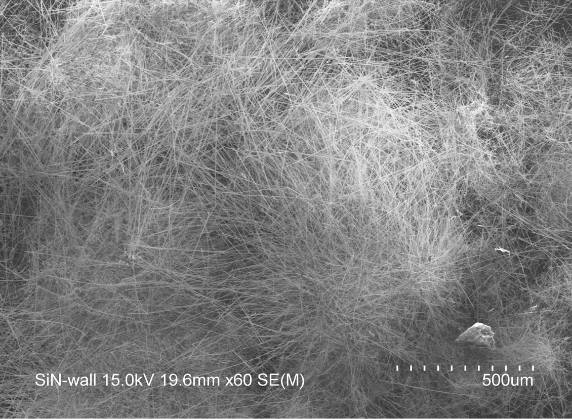
Figure 5. Silicon nitride nanofibers grown on a graphite plate substrate using silica nanopowder precursor.
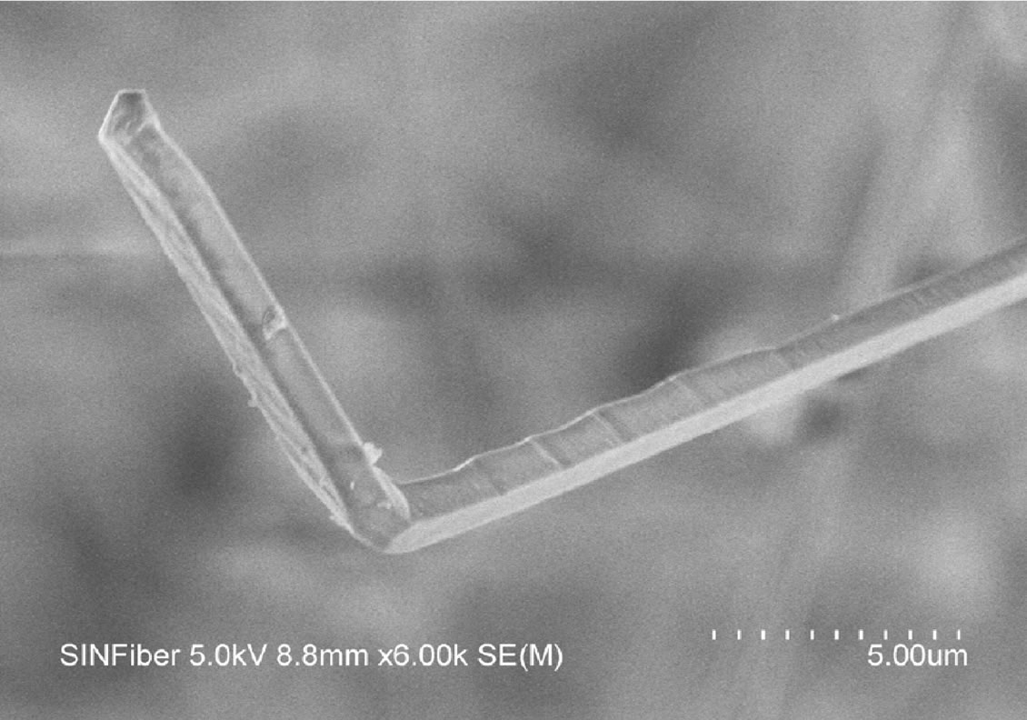
Figure 6. Morphology of silicon nitride nanofibers grown using silica nanopowder precursor shows a predisposition to a rectangular cross section.
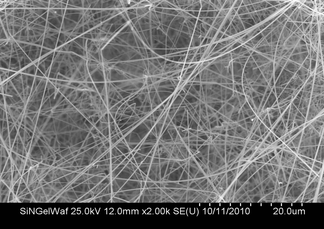
Figure 7. Morphology of silicon nitride nanofibers grown using silica gel precursor shows a predisposition to a circular cross section.
for silicon nitride as the chemical composition. Figure 10 shows the ATR-FTIR spectrum (Perkin Elmer Spectrum One) indicating the presence of silicon nitride.
The X-ray powder diffraction pattern (Siemens D500) in Figure 11 shows the presence of crystalline alpha silicon nitride, thus confirming that the nanofibers, irrespective of the precursor and the orientation of the crucible/ pellets, are crystalline alpha silicon nitride. To prepare nanofiber samples for X-ray diffraction analysis, it was a lot easier to extract/separate the fibers from the graphite plate substrates than the raw pellets. Hence, from a mass production perspective, it would be beneficial if the predominant growth of the fibers occurred on the graphite plate substrates.
Several mechanisms have been proposed for the formation of silicon nitride nanowires and nanofibers in a process such as this. The absence of droplet shapes at the tips of the fibers is indicative of a vapor solid mechanism at work. The raw pellets release a SiO gas cloud at 1450˚C and the cloud interacts with the flowing nitrogen gas. The dense cloud of the SiO gas exchanges nitrogen with oxygen to form the solid silicon nitride nanofibers on the graphite plates (Figure 12). The reactions that produce the nanofibers at the temperature of 1450˚C are:
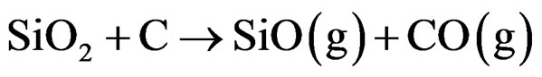 (1)
(1)
 (2)
(2)
The flow of nitrogen gas should not be too strong to blow away the SiO gas cloud in order to favor the formation of Si3N4 nanofibers. Experimentally it was found that high flow rates of nitrogen gas reduced the growth of nanofibers. Hence a critical flow rate of nitrogen gas and a sufficient supply of the gas are crucial to the process. The results from arrangement 3 where silicon nitride fibers grew mostly at the bottom of the crucible indicate that a stable SiO gas cloud is essential for the process. Based on Equation (1), it is important to mix the silica source with charcoal to form the raw pellet. Equation (2) suggests that the graphite plates provide assistance as well as a site for the formation of the fibers. It was also observed that grooves on the graphite plates promote long Si3N4 nanofibers.
4. Conclusion
Crystalline silicon nitride nanofibers were formed on the surface of graphite plates and raw silica pellets by the carbothermal reduction method for both precursors: silica nanopowders and silica gel. The silicon nitride nanofibers appear with a predominantly rectangular cross section from silica nanopowder precursors and with a circular cross section for silica gel precursors. Silica gel precursors provide nanofiber products that are smaller in cross section but longer than the products from silica nanopowder precursors. Using the silica nanopowder precursors, silicon nitride nanofibers grow mostly on the graphite plate substrates instead of on the surface of the
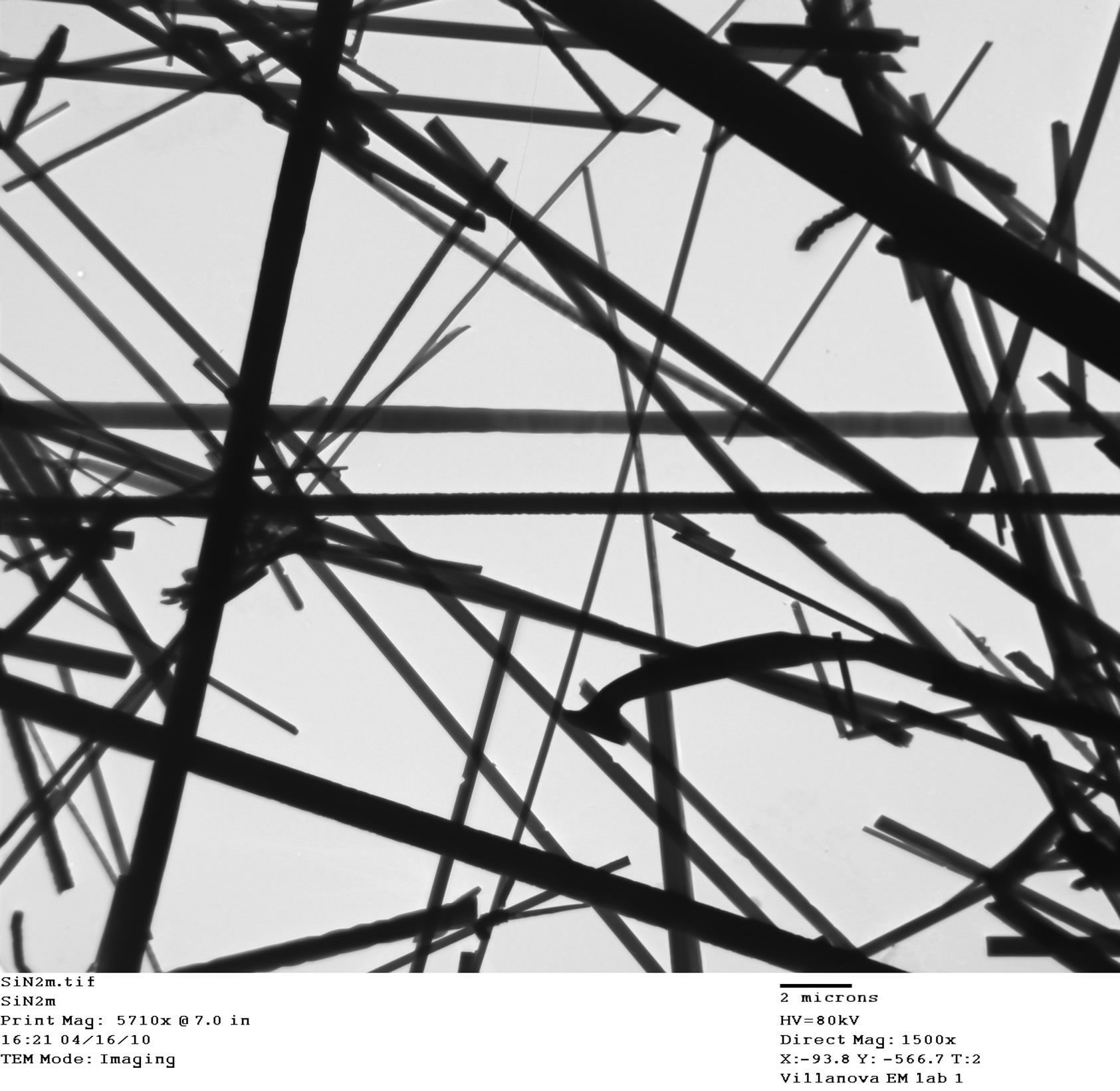

Figure 8. Transmission electron microscope images of nanofibers grown from (top) graphite plate substrate and (bottom) raw pellet.
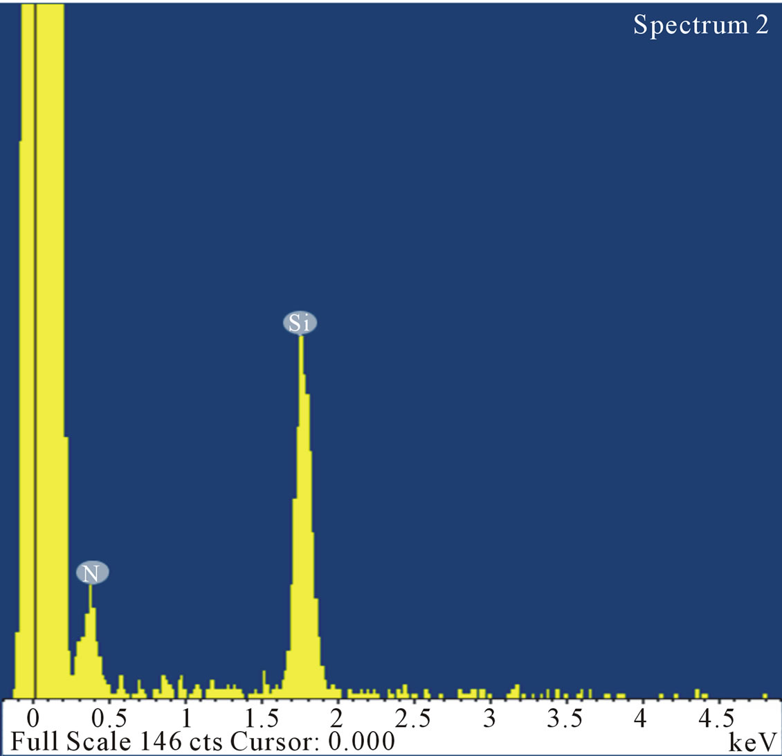
Figure 9. Energy dispersive spectroscopy pattern of nanofibers indicating strong peaks of silicon and nitrogen.
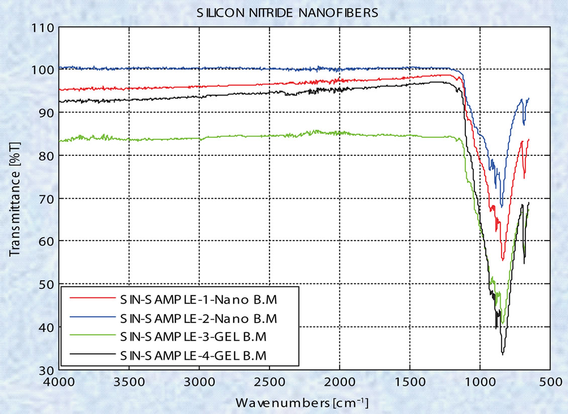
Figure 10. ATR-FTIR spectra of nanofibers indicating strong absorption corresponding to silicon nitride.
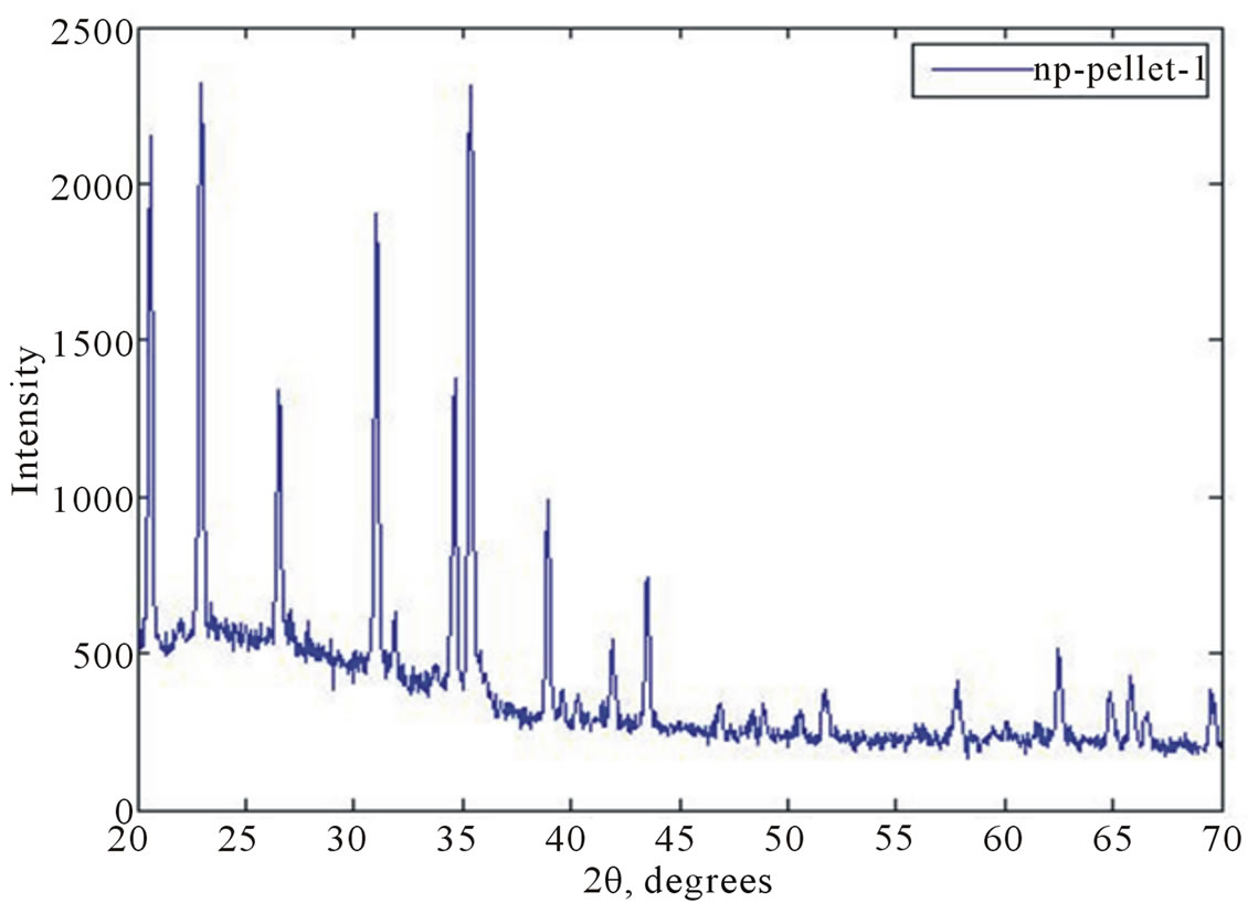
Figure 11. X-ray diffraction pattern for the nanofibers indicating alpha silicon nitride.
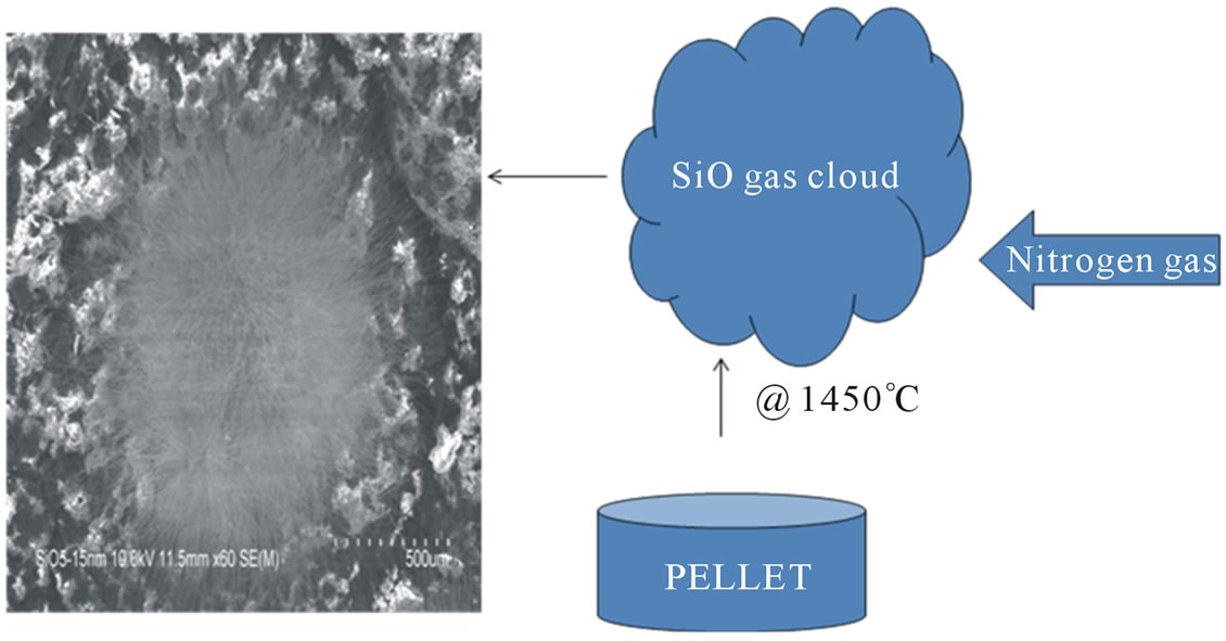
Figure 12. Nitrogen cloud trapping mechanism for formation of silicon nitride nanofibers.
pellets. Nanofibers can be easily removed from the graphite plates with very low contamination. For the same base material, thinner nanofibers grow on the graphite plate surfaces than on the raw pellet surfaces. Finally the geometrical arrangement of the silica raw pellets and graphite plate substrates does influence the density of nanofiber growth. It is important for this arrangement to maximize the surface area exposed to the flow of nitrogen. It is also important to control the flow of nitrogen gas in order not to disrupt the cloud of SiO gas that is responsible for the growth of the silicon nitride nanofibers by the vapor solid mechanism.
5. Acknowledgements
This work was supported by a grant from the Delaware County Keystone Innovation Zone, Pennsylvania and by a Major Research Instrumentation (MRI) grant from the National Science Foundation (NSF).
REFERENCES
- G. Y. Li, X. D. Li, H. Wang and Z. Q. Li, “Long Silicon Nitride Nanowires Synthesized in a Simple Route,” Applied Physics A, Vol. 93, No. 2, 2008, pp. 471-475. doi:10.1007/s00339-008-4808-4
- F. Wang, G. Q. Jin and X. Y. Guo, “Formation Mechanism of Silicon Nitride Nanowires via Carbothermal Reduction of Carbonaceous Silica Xerogels,” Journal of Physical Chemistry B, Vol. 110, No. 30, 2006, pp. 14546- 14549. doi:10.1021/jp0619282
- D. Y. Pan, S. Y. Zhang, Y. Q. Chen and J. G. Hou, “Hydrothermal Preparation of Long Nanowires of Vanadium Oxide,” Journal of Materials Research, Vol. 17, No. 8, 2002, pp. 1981-1984. doi:10.1557/JMR.2002.0293
- C. N. R. Rao, G. Gundiah, F. L. Deepak, A. Govindaraj and A. K. Cheetham, “Carbon Assisted Synthesis of Inorganic Nanowires,” Journal of Materials Chemistry, Vol. 14, 2004, pp. 440-450. doi:10.1039/b310387k
- X. C. Wu, W. H. Song, B. Zhao, W. D. Huang, M. H. Pu, Y. P. Sun and J. J. Du, “Synthesis of Coaxial Nanowires of Silicon Nitride Sheathed with Silicon and Silicon Oxide,” Solid State Communications, Vol. 115, No. 12, 2000, pp. 683-686. doi:10.1016/S0038-1098(00)00255-6
- C. J. Deng, P. Yu, M. Y. Yau, C. S. Ku and D. H. L. Ng, “Fabrication of Single Crystal Alpha Alumina Nanorods by Displacement Reactions,” Journal of the American Ceramic Society, Vol. 86, No. 8, 2003, pp. 1385-1388. doi:10.1111/j.1151-2916.2003.tb03480.x
- W. Yang, Z. Xie, J. Li, H. Miao, L. Zhang and L. An, “Ultra-Long Single-Crystalline a-Si3N4 Nitride Nanowires: Derived from a Polymer Precursor,” Journal of the American Ceramic Society, Vol. 88, No. 6, 2005, pp. 1647-1650. doi:10.1111/j.1551-2916.2005.00270.x
- Y. Zhang, N. Wang, R. He, J. Liu, X. Zhang and J. Zhu, “A Simple Method to Synthesize Silicon Nitride and Silica Nanowires from Silicon or Silicon/Silica Mixture,” Journal of Crystal Growth, Vol. 233, No. 4, 2001, pp. 803-808. doi:10.1016/S0022-0248(01)01650-5
- H. Arik, “Synthesis of Silicon Nitride by the CarboThermal Reduction and Nitridation of Diatomite,” Journal of the European Ceramic Society, Vol. 23, No. 12, 2003, pp. 2005-2014. doi:10.1016/S0955-2219(03)00038-4
- X. C. Wu, W. H. Song, W. D. Huang, M. H. Pu, B. Zhao, Y. P. Sun and J. J. Du, “Simultaneous Growth of a-Si3N4 and β-SiC Nanorods,” Materials Research Bulletin, Vol. 36, No. 5-6, 2001, pp. 847-852. doi:10.1016/S0025-5408(01)00571-2
- L. D. Zhang, G. W. Meng and F. Phillipp, “Synthesis and Characterization of Nanowires and Nanocables,” Materials Science and Engineering A, Vol. 286, No. 1, 2000, pp. 34-38. doi:10.1016/S0921-5093(00)00664-X
- M. G. Chaudhari, S. K. Ahmadullah, R. Dey, G. C. Das, S. Mukherjee and M. K. Mitra, “Novel Techniques for Synthesis of Silicon Nitride Nanowires,” Advances in Applied Ceramics, Vol. 110, No. 4, 2011, pp. 211-214. doi:10.1179/1743676111Y.0000000003
- G. J. Qi, “Si-N-C Nanowires Derived by Polyhydridomethylsilazane Pyrolysis,” Materials Sciences and Applications, Vol. 2, 2011, pp. 936-939. doi:10.4236/msa.2011.27124
- C. Xu, M. Kim, J. Chun, D. E. Kim, B. Chon, S. Hong and T. Joo, “Gallium Doped Silicon Nitride Nanowires Sheathed with Amorphous Silicon Oxynitride,” Scripta Materialia, Vol. 53, No. 8, 2005, pp. 949-954. doi:10.1016/j.scriptamat.2005.06.024
- M. Bechelany, A. Brioude, S. Bernard, G. Ferro, D. Cornu and P. Miele, “Large Scale Preparation of Faceted Silicon Nitride Nanorods from Beta Silicon Carbide Nanowires,” Nanotechnology, Vol. 18, 2007, pp. 1-6. doi:10.1088/0957-4484/18/33/335305
- S. Motojima, S. Ueno, T. Hattori and K. Goto, “Growth of Regularly Coiled Spring Like Fibers of Silicon Nitride by Iron Impurity Activated Chemical Vapor Deposition,” Applied Physics Letters, Vol. 71, No. 16, 1997, pp. 1001- 1003. doi:10.1063/1.101422
- H. Y. Kim, J. Park and H. Yang, “Synthesis of Silicon Nitride Nanowires Directly from the Silicon Substrates,” Chemical Physics Letters, Vol. 372, No. 1-2, 2003, pp. 269-274. doi:10.1016/S0009-2614(03)00428-7
- W. Han, S. Fan, Q. Li, B. Gu, X. Zhang and D. Yu, “Synthesis of Silicon Nitride Nanorods Using Carbon Nanotube as a Template,” Applied Physics Letters, Vol. 54, No. 11, 1989, pp. 2271-2273. doi:10.1063/1.120550
- G. Zou, B. Hu, K. Xiong, H. Li, C. Dong, J. Liang and Y. Qian, “Single Crystalline Alpha Silicon Nitride Nanowires: Large-Scale Synthesis, Characterization, and Optic Properties,” Applied Physics Letters, Vol. 86, No. 18, 2005, Article ID: 181901. doi:10.1063/1.1915509
- H. Zhang, S. Zhang, S. Pan and J. Hou, “Synthesis and Characterization of Several Alpha Silicon Nitride Nanostructures,” Journal of the American Ceramic Society, Vol. 88, No. 3, 2005, pp. 566-569. doi:10.1111/j.1551-2916.2005.00130.x
- S. Ren, F. Ji and X. He, “Mechanosynthesis of Silicon Nitride Nanowires,” Advanced Materials Research, Vol. 148, 2011, pp. 1347-1350. doi:10.4028/www.scientific.net/AMR.148-149.1347