Journal of Modern Physics
Vol. 2 No. 9 (2011) , Article ID: 7134 , 4 pages DOI:10.4236/jmp.2011.29113
The Effect of a Multihollow Cathode on the Self-Bias Voltage of Methane RF Discharge Used for a-C:H Deposition
1Laboratoire des Plasmas, Centre de Développement des Technologies Avancées, Baba Hassen, Algiers, Algeria
2Laboratoire de Physique Théorique, Faculté de Physique, USTHB, Algiers, Algeria
E-mail: sdjerourou@cdta.dz
Received March 9, 2011; revised April 16, 2011; accepted April 28, 2011
Keywords: Multihollow Cathode, RF (13.56 MHz) Discharge, CH4 Plasma, Self-Bias Voltage, a-C:H
ABSTRACT
In this work we report the measurement of the self-bias voltage of radiofrequency (RF) capacitevely coupled plasma, with a multihollow cathode and methane precursor, used for amorphous hydrogenated carbon (aC:H) thin film deposition. The plasma is produced in the incident power and pressure ranges between 20 - 300 W and 10 - 100 mTorr, respectively. It was found that the self-bias voltage Vdc is a linear function of the square root of the incident power WRF. The relationship between the self-bias voltage and gas pressure P is established; this gives an empirical relation for . From this result, the pressure
  corresponding to the transition from hollow cathode effect to hollow cathode arc effect is determined.
1. Introduction
The amorphous hydrogenated carbon films (a-C:H) that are typically dense, hard and transparent are of great interest in different areas of sciences and technology; such as in microelectronics, IR spectroscopy; instrumental and medical industries [1-6]. Various deposition methods are used such as arc [7], sputtering [8,9] and plasma enhanced chemical vapor deposition (PECVD) [10,11]. However, changing the system operation parameters, in particular gas pressure and incident power can strongly affect the deposited film structure and properties [11,12]. The geometry of the cathode plays also a crucial role on the plasma parameters, such as the energy and flux of ions that strike the film surface, which can affect the deposition parameters like growth rate of the deposited film [13]. This is why it is so important to make coupling between the plasma parameters, the system operation parameters and the geometry of the cathode for controlling and understanding the basic mechanisms and also to improve the film deposition. Frequently, the capacitevely radio frequency (RF) discharge with parallel-plate electrode is widely used for the deposition of a-C:H because the apparatus system is very simple. But they present a disadvantage, the electron density and deposition rate are lower regarding other configuration. Consequently, the other alternative geometry can be used such as hollow cathode, which is widely used as a light source [14], and active media for gas lasers [15], these discharges are recognized to produce denser plasma [16]. Recently, there are interests to use the hollow cathode discharge for the deposition of thin films, because they gives the possibility to produce plasma with higher electron density and lower electron temperature, that reduces the damage caused to the film deposition [17]. For this purpose, Ohtsu et al. [18] have used multihollow cathode discharges for deposition of diamondlike-carbon (DLC) thin film at 13.56 MHz in methane gas, and they prove that they achieved a high deposition rate of DLC film. Their investigation concerns a cathode with 35 small holes. In the present study we focus on using multihollow cathode with seven (07) holes and each hole has 40 mm of diameters used for the deposition of amorphous hydrogenated carbon films (a-C:H) with CH4 gas precursor at 13.56 MHz frequency. We are interested in the influence of the system operation parameters on the self-bias voltage. The latter has been subject of many researches carried out in the fields of electric diagnostics of the RF (13.56 MHz) discharges [19,20]. The self-bias voltage is macroscopic parameters is known to have a major influence on the film deposition, the impact of ions energies on the substrate are to be taken only as approximate values; as often reported, where only the self-bias voltage (Vdc) is given, as pointed out by Catherine et al. [20] in the study of the electric behaviour of 13.56 MHz discharge in CH4 used for a-C:H film deposition.
This paper is organized as follows: In Section 2 a description of the experimental setup will be given. Results and discussion will follow in Section 3, and in Section 4 the conclusions are summarized.
2. Experimental Setup
The experimental setup used in the present study is shown in Figure 1. The ionization chamber consisted of a stainless steel cylindrical vessel of 230 mm diameter and 260 mm height. The electrode creator of plasma is a multihollow cathode, of 126 mm diameter and 50 mm height, with seven holes. Each hole has 40 mm inner diameter and 50 mm height. The wafer holder (bottom electrode) of 150 mm diameter is situated at 50 mm from the upper electrode, which is capacitively coupled to the RF (13.56 MHz) generator through a matching network. The ionization chamber walls were grounded (asymmetrical diode-type reactor), and a base vacuum of less than 10–5 mbar is achieved by the pumping system. The range of variation of the incident power and pressure are 20 - 300 W and 10 - 100 mTorr respectively. A self-bias voltage is measured with a voltmeter through a low pass filter, and the saturation ion current density is collected at the wafer holder that is a dc polarized.
3. Results and Discussions
The knowledge of the electric parameters of the dis
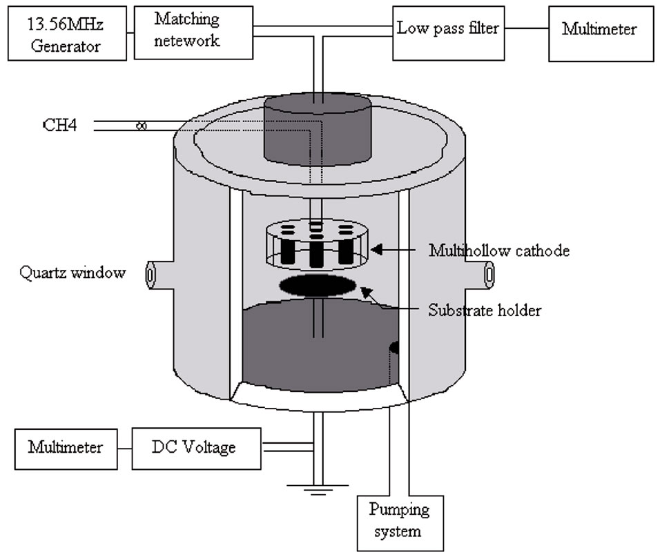
Figure 1. Experimental setup.
The knowledge of the electric parameters of the discharge such as the self-bias voltage (Vdc) is of crucial importance for understanding the electric behaviour of the discharge. Thus, we have studied the evolution of this electric parameter as a function of incident power and pressure.
The self-bias voltage Vdc. The self-bias voltage was modeled by different authors in various plasma discharges. Using the capacitive sheath model, Y. Catherin [20] gives the dependence of the self-bias voltage on incident power and pressure in the case of RF parallel plate electrode discharge by the following equation:
 (1)
(1)
where WRF is the incident power and P is the pressure Another expression of the self-bias voltage can be obtained from the cathode layer model in the case of discharge with RF antenna [21]:
 (2)
(2)
where a is constant depend on the plasma parameters, WRF is the incident power and P is the pressure. It can be seen from both Equations (1) and (2), that the self-bias voltage has the same dependence on incident power and differ with pressure; because the variation of the self-bias voltage with pressure is related to the sheath thickness which depends on the cathode geometry.
Figure 2 represents the variation of the self-bias voltage Vdc versus the square root of the incident power WRF0.5 at different gas pressure; the self-bias voltage is proportional to the square root of the incident power, this can be attributed to plasma volume with resistive behaviour [20]. The same evolution was observed in the cases of parallel plate and antenna cathode [20-22]. This result confirms that the evolution of the self-bias voltage with

Figure 2. Influence of the square root of incident power on the self-bias voltage.
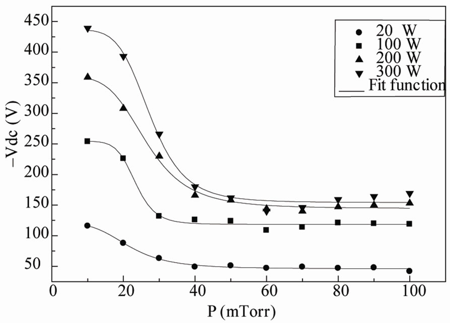
Figure 3. Influence of the pressure on the self-bias voltage.
incident power is independent of the cathode geometry.
The variation of the self-bias voltage with the pressure is shown in Figure 3. We can split these curves on two parts: at low pressure (10 - 40 mTorr) we notice a fast decrease of the self-bias voltage. This can be attributed to the hollow cathode effect, which is manifested by an abrupt decrease in the operating voltage [23,24].
For the pressure ranging in the domain 40 - 100 mTorr, the self-bias voltage became constant, this behaviour may be due to the transition of the discharge to the hollow cathode arc discharge [24].
The fitting corresponding to our experimental results can be expressed by the following empirical relation:
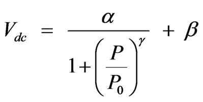 (3)
(3)
where α, β and γ are constants that depend on the system operation parameters. P0 is the pressure corresponding to the inflection point. The result of fitting procedures showed a very good agreement with our experimental results. In Table 1 we summarized the parameter of Equation (3) which are depend on the incident power.
The key fit parameter P0 represents the transition of the discharge from an regime to an other. At this values of pressure, the self-bias voltage change his behaviour.
From the variation of the self-bias voltage versus pressure, we can establish the transition pressure of the discharge regime, which represents the passage from
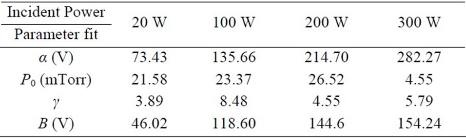
Table 1. Empirical function fit parameters.
hollow cathode to hollow cathode arc discharge.
4. Conclusions
In this work we studied the electrical parameters of 13.56 MHz capacitive discharge used for the deposition of aC:H film, with multihollow cathode. It was shown that, the self-bias voltage is linear function of WRF0.5 independent of the geometry of the cathode. From the dependence of the self-bias voltage on pressure an empirical relation is deduced: Vdc ~ (P/P0)γ. From this result, the transition pressure  from hollow cathode to hollow cathode arc effect was determined.
REFERENCES
- K. Luo, Y. Q. Fu, H. R. Le, J. A. Williams, S. M. Spearing and W. I. Milne, “Diamonde and Diamonde-Like Carbon MEMS,” Journal of Micromechanics and Microengineering, Vol. 17, No. 1, June 2007, pp. S147-S163. doi:10.1088/0960-1317/17/7/S12
- A. Tibrewala, E. Peiner, R. Bandorf, S. Biehl and H. Lüthje, “The Piezoresistive Effect in Diamonde-Like Carbon Films,” Journal of Micromechanics and Microengineering, Vol. 17, No. 7, June 2007, pp. S77-S82. doi:10.1088/0960-1317/17/7/S03
- R. Hauert, “Tribology of Diamond-Like Carbon Films: Fundamentals and Applications,” Springer, New York, 2008.
- S. Tinchev, P. Nikolova, S. Balabanov and N. Georgiev, “Amorphous Hydrogenated Carbon Coating for Thermal Solar Collectors,” Journal of Physics: Conference Sries, Vol. 113, 2008, p. 1.
- E. Peiner, A. Tibrewala, R. Bandorf, H. Lüthje, L. Doering and W. Limmer, “Diamond-Like Carbon for MEMS,” Journal of Micromechanics and Microengineering, Vol. 17, No. 7, June 2007, pp. S83-S90. doi:10.1088/0960-1317/17/7/S04
- W. I. Milne, “Electronic Device from Diamonde-Like Carbon,” Semiconductor Science and Technology, Vol. 18, February 2003, pp. S81-S85. doi:10.1088/0268-1242/18/3/312
- E. Neyts, A. Bogaerts and M. C. M. van de Sanden, “Reaction Mechanisms and Thin a-C:H Film Growth from Low Energy Hydrocarbon Radicals,” Journal of Physics: Conference Series, Vol. 86, No. 1, 2007, pp. 1-15.
- P. Wang, X. Wang, W. M. Liu and J. Y. Zhang, “Growth and Structure of Hydrogenated Carbon Films Containing Fullerene-Like Structure,” Journal of Physics D: Applied Physics, Vol. 41, No. 8, March 2008, pp. 1-7. doi:10.1088/0022-3727/41/8/085401
- G. Romyani, J. Tapati and R. Swati, “Transparent Polymer and Diamond-Like Hydrogenated Amorphous Carbon Thinfilms by PECVD Technique,” Journal of Physics D: Applied Physics, Vol. 41, No. 15, July 2008, pp. 1-7.
- F. Zhao, H. X. Li, L. Ji, Y. F. Mo, W. L. Quan, H. D. Zhou and J. M. Chen, “Structural, Mechanical and Tribological Characterizations of a-C:H:Si Films Prepared by Hybrid PECVD and Sputtering Technique,” Journal of Physics D: Applied Physics, Vol. 42, No. 16, July 2009, pp. 1-13. doi:10.1088/0022-3727/42/16/165407
- N. M. S. Marins, R. P. Mota, D. C. R. Santos, R. Y. Honda, M. E. Kayama, K. G. Kostov, M. A. Algatti, N. C. Cruz and E. C Rangel, “Amorphous Hydrogenated Carbon Films Treated by SF6 Plasma,” Journal of Physics: Conference Series, Vol. 167, No. 1, 2009, pp. 1-4.
- L. Gabriel, “Influence of the Substrate-Electrode Applied Bias Voltage on the Properties of Sputtered a-C:H Thin Films,” Journal of Physics: Condensed Matter, Vol. 13, No. 13, 2001, pp. 3011-3021. doi:10.1088/0953-8984/13/13/314
- H. Águas, R. Martins and E. Fortunato, “Plasma Dianostics of a PECVD System Using Different R.F. Elec Trode Configurations,” Vacuum, Vol. 56, No. 1, January 2000, pp. 31- 37.
- K. Sommeri, A. P. Thorne and R. C. M. Learner, “An Active Filter for Inert Gas Lines in a Hollow Cathode Light Source,” Journal of Physics D: Applied Physics, Vol. 16, No. 3, 1983, pp. 233-244. doi:10.1088/0022-3727/16/3/006
- D. Mihailova, J. van Dijk, M. Grozeva, G. J. M. Hagelaar and J. J. A. M. van der Mullen, “A Hollow Cathode Discharge for Laser Applications: Influence of the Cathode Length,” Journal of Physics D: Applied Physics, Vol. 43, No. 14, March 2010, pp. 1-9. doi:10.1088/0022-3727/43/14/145203
- A. Von Engel, “Ionized Gases,” Clarendon, Oxford, 1955.
- K. Yambe, “Property of Plasma by Radio Frequency Discharge with the Us of Multi Hollow Cathods,” Journal of Physics: Conference Series, Vol. 106, 2008, pp. 1-5.
- Y. Ohtsu and H. Fujita, “Production of High-Density Capacitive Plasma by the Effect of Multihollow Cathode Discharge and High-Secondary-Electron Emission,” Applied Physics Letters, Vol. 92, No. 17, April 2008, pp. 1-3.
- A. Pastol and Y. Catherine, “Optical Emission Spectroscopy for Diagnostic and Monitoring of CH4 Plasmas Used for a-C:H Deposition,” Journal of Physics D: Applied Physics, Vol. 23, No. 7, 1990, pp. 799-805. doi:10.1088/0022-3727/23/7/008
- Y. Catherine and P. Couderc, “Electrical Characteristics and Growth Kinetics in Discharges Used for Plasma Depo Sition of Amorphous Carbon,” Thin Solid Films, Vol. 144, No. 2, 1986, pp. 265-280. doi:10.1016/0040-6090(86)90419-0
- C. Riccardi, R. Barni, M. Fontanesi, B. Marcandalli, M. Massafra, E. Selli and G. Mazzone, “A SF6 RF Plasma Reactor for Research on Textile Treatment,” Plasma Sources Science and Technology, Vol. 10, No. 1, 2001, pp. 92-98. doi:10.1088/0963-0252/10/1/312
- S. Peter, K. Graupner, D. Grambole and F. Richter, “Comparative Experimental Analysis of the a-C:H Deposition Processes Using CH4 and C2H2 as Precursors,” Journal of Applied Physics, Vol. 102, No. 5, 2007, pp. 1-18. doi:10.1063/1.2777643
- E. Oks, “Plasma Cathode Electron Sources: Physics, Technology, Applications,” Wiley-Vch Verlag GmbH & Co.KGaA, Weinheim, 2006.
- H. Barankova, “Proceedings of International Symposium on Thin Film Materials, Processes, Reliability, and Applications: Thin Film Processes,” Electrochemical Society Inc, Pennington, 1998.