Applied Mathematics
Vol.5 No.10(2014), Article ID:46186,5 pages DOI:10.4236/am.2014.510134
A New Correction Algorithm of the Eccentric Ultrasonovision Time Image in the Casing Hole
Jihui Tu1, Bin Yang2
1Electronics & Information School, Yangtze University, Jingzhou, China
2Electronic information Engineering School, HEBI College of Vocation and Technology, Hebi, China
Email: green666@126.com
Copyright © 2014 by authors and Scientific Research Publishing Inc.
This work is licensed under the Creative Commons Attribution International License (CC BY).
http://creativecommons.org/licenses/by/4.0/


Received 6 April 2014; revised 6 May 2014; accepted 13 May 2014
ABSTRACT
The ultrasonovision image caused by the tool eccentricity can often present two pieces of vertical black strips in the Casing Well. To solve this problem, this paper proposes a correction algorithm of time eccentricity image based on ellipse fitting algorithm. This algorithm firstly utilizes borehole diameter data to fit ellipse and compute ellipse’s center, major axis, minor axis and inclination angle and other parameters, and then uses these parameters to correct eccentrical ultrasonovision time image. The tested results show that the algorithm can accurately fit ellipse and correct the eccentrical ultrasonovision time image, which is very important practical significance on processing the well logging.
Keywords:BHTV, Ellipse Fitting, Image Correction, Tool Eccentricity

1. Introduction
The principle of ultrasound imaging logging technique is to image the surface of the wall by the amplitude and time of ultrasonic echo after the emission of ultrasound to the wall perpendicularly through a rotating energy transducer. When the technique is used to image the inner wall of cased wells, we can know corrosion, deformation of the casing pipes and to detect the locations of casing perforation and couplings [1] [2] . When it is applied to imaging the side wall of the holes, we can find out the developing status of wall cracks, holes and collapse. In a cased well, when instrument eccentricity causes non-perpendicular emission of ultrasound, the amplitude of ultrasonic echo from inner wall of the casing pipe will be weakened and the time will not be accurate, and this would result in two vertical dark bands in the ultrasonic time image. These dark bands can cover up a lot of real information about the wall and disenable the log interpreter to make the correct judgment. Since instrument eccentricity is a common occurrence in practical logging process, it is of great significance to find a method to eliminate such dark bands.
In order to solve the problem of dark bands caused by instrument eccentricity, this paper presents a correction algorithm for eccentric time image based on ellipse fitting method. Firstly, the algorithm does an ellipse fitting on the hole diameter logging data obtained from ultrasonic logging, to calculate the parameters such as its center, long axis, short axis and slope, and then use these parameters to correct the eccentricity problem of the time image on ultrasonic TV. The experimental results show that the algorithm is capable of eliminating the dark bands and making the information of the casing surface displayed more clearly. And this is of great value for the practical processing of logging data.
2. The Instrument Eccentric Principle [3] [4]
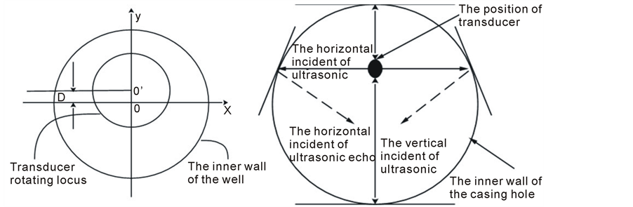
In cased well, when the downhole instrument generates eccentricity, acoustic transducer launch oblique incidence, the eccentric instrument will affect the ultrasonic echo amplitude and time. The following accounts for the eccentric effect on imaging from the principle of ultrasonic imaging.
When the device is the eccentric, the cross section of the well casing is shown in Figure 1(a). Transducer in the y direction is eccentric and the eccentricity distance is D. The incident and echo wave of transducer is shown in Figure 1(b), the instrument eccentric causes the non-normal incidence and reflection of the ultrasonic wave, even if the same conditions of reflection coefficient in the well week, the part reflection wave deviate the range accepted by transducer, the transducer can't receive the echo information. At the same time, the incident angle of the ultrasound wave is changed in the different rotational position because of the transducer eccentricity, the values of the echo amplitude is also changed in the same smoothness degree of the well week.
The ultrasonovision image caused by the tool eccentricity can often appear two pieces of vertical black strips in the casing well, the dark place is corresponding near the eccentric vertical direction. Therefore, in the case of a down hole instrument eccentric ultrasonic television image can no longer completely correctly reflect the acoustic impedance characteristics of the wall of well, the echo wave time cannot reflect the size of the well radius, which affects the interpretation and judgment of logging image.
3. The Correction Algorithm of Time Image
3.1. Ellipse Fitting Algorithm [5]
During the process of ultrasonic television imaging logging, ultrasonic transducer rotating scanning a circle gets the several time callback data in a week, which estimates the parameters for the ellipse fitting of well section. The elliptical curve fitting uses least squares fitting algorithm, the basic algorithm [5] and the result of experiments is described in the text [6] .
3.2. The Correction Algorithm
In Figure 2, if ellipse center(x0,y0) obtained by ellipse fitting is not (0,0), it presents that the instrument generates eccentricity. According to the parameters of ellipse fitting, eccentricity of well data is corrected. The algorithm is as follows:
1) The ith point well radius of the wall is Ri, the coordinate is:
 (1)
(1)
The distance from ith point to ellipse center (x0, y0) is , we have
 (2)
(2)
The angle of ith point is  in the (x0, y0) as the origin of coordinates, when ith point is the first quadran in the coordinate system,
 ; when ith point is the second quadran in the coordinate system,
 (a) (b)
Figure 1. (a) The section diagram of the instrument eccentric in the casing hole; (b) The amplitude diagram of Acoustic echo.
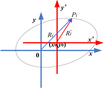
Figure 2. geometric diagram of instrument eccentricity.
 ;when ith point is the third quadran in the coordinate system,
 ;
;
when ith point is the fourth quadran in the coordinate system, .
.
2) To sort for  from small to big. According to (
 ,
, ), 1 ≤ I ≤ N, we use the interpolation arithmetic to calculate
  in the Equal interval Angle
  (
( ). If
). If , where
 (3)
(3)
According to the above algorithm, calculate one by one the value of the well radius in the equal interval angle, which realizes to correct the instrument eccentricity.
4. Testing and Results
In order to verify the correctness and validity of eccentricity correction algorithm, experiments are conducted to test eccentricity correction algorithm with standard image and the actual logging image. Since the algorithm has already been included in Chinese Logging Corporation’s comprehensive logging platform Leader 3.0, the experiments are carried out under this platform.
Figure 3 shows the results of the estimation and correction of hole diameter data of the perfect circle at different positions of the eccentricity theoretical model. For a well section in the shape of a perfect circle, the time image of a hole diameter should be evenly gray. In the case of eccentricity, the time image is represented by two obvious vertical dark bands. When there is a certain eccentricity distance and different eccentricity positions, the dark bands will be horizontally staggered, as is shown in the “time curve” image on the left side of Figure 3. After estimating the center by ellipse fitting and correcting the time image, we can get a time image with a similar even gray to that in the perfect circle, as is shown in the “final time curve” image in Figure 3. Figure 4 demonstrates the effects resulted from ellipse fitting of logging data of Sai 51-3 inclined shaft and correction of its hole diameter time. From the figure we can notice that, after the correction of its eccentricity time image, the dark bands disappear and the details of the image become clearer.
From the results of experiments, the method can elliptically fit the hole diameter quite accurately, and the fitting result can be used to correct eccentricity time image.
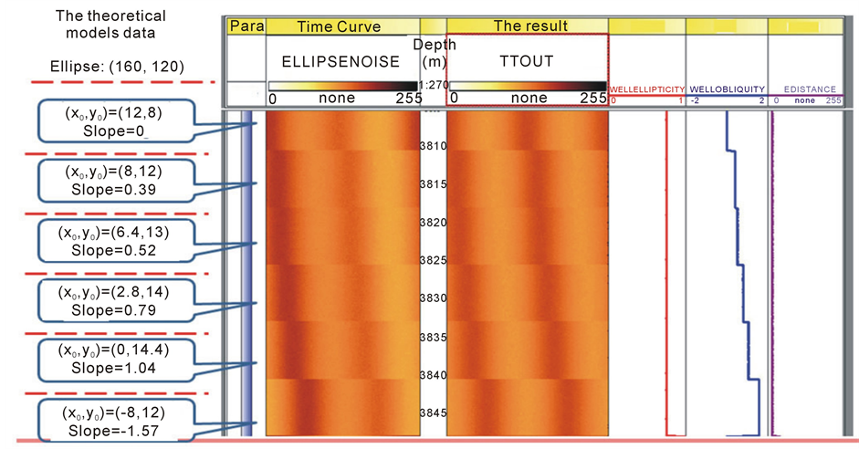
Figure 3. The instrument eccentricity is corrected in the theoretical models.
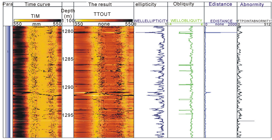
Figure 4. The instrument eccentricity is corrected in the Sai 51-3 well.
5. Conclusion
The paper presents the eccentric correction algorithm based on ellipse fitting of the hole diameter, to solve the problem of the appearance of two obvious dark bands in ultrasonic logging images caused by instrument eccentricity. The algorithm uses the known hole diameter data to do ellipse fitting and calculate the parameters of the fitting ellipse such as the center of ellipse, the long axis, the short axis and the slope. With those parameters, we can correct the eccentricity time image on ultrasonic TV. The experiments prove that the method is able to do the ellipse fitting with accuracy and correct the eccentricity time image by eliminating the dark bands in the image and significantly improving the quality of the image, which is of great practical value for the actual processing of the logging data.
References
- Pang, J.F., et al. (2008) Logging Principle and Instrument. Science Press, Beijing, 328-353.
- Lu, F., Gao, H.J. and Li, J. (2009) A High Performance Ultrasonic TV Imaging Logging Tool. Well Logging Technology, 33, 275-278.
- Yu, H.Q., Qu, W.L. and Huang, Z.L. (1997) The Influences of Tool Eccentricity in a Casing Well on Ultrasonic Echo. Journal of Huazhong University of Science and Technology, 25, 40-43.
- Yu, H.Q., Qu, W.L. and Huang, Z.L. (1999) Influence of Tool Eccentricity in a Well Casing on the Ultrasonic Televiewer Image and Its Correction Processing. Applied Acoustics, 18, 16-20, 43.
- Liu, S.G., Li, P. and Na, Y.L. (2002) Evaluation of the Form Error of Ellipse Based on Least Square Method. Acta Metrologica Sinica, 23, 245-247.
- Tu, J.H. and Yang, B. (2014) The Research of Ellipse Parameter Fitting Algorithm of Ultrasonic Imaging Logging in the Casing Hole. Applied Mathematics, 5, 1317-1321.