Wireless Engineering and Technology
Vol.05 No.03(2014), Article ID:47771,13 pages
10.4236/wet.2014.53009
Performances of Micropower UWB Radar Using Orthogonal Waveforms
Laila Sakkila1*, Atika Rivenq1, Charles Tatkeu2, Yassin Elhillali1, Jean-Pierre Ghys2
1IEMN/DOAE, University of Valenciennes, Valenciennes, France
2IFSTTAR/LEOST, Villeneuve d’Ascq, France
Email: *laila.sakkila@univ-valenciennes.fr, Laila.sakkila@gmail.com
Copyright © 2014 by authors and Scientific Research Publishing Inc.
This work is licensed under the Creative Commons Attribution International License (CC BY).
http://creativecommons.org/licenses/by/4.0/


Received 4 April 2014; revised 6 May 2014; accepted 2 June 2014
ABSTRACT
Radars and their applications were, for a long time, reserved to national defense, air security or weather service domains. For a few years, with the emergence of new technologies, radar applica- tions have been developed and have become known in the civil domain. In particular, the arrival of UWB―Ultra-Wideband technology allows the design of compact and low-cost radars with multi- ple fields of application. In this paper, we focus on road applications, such as driving assistance with the objective of increasing safety and reducing accidents. In classical UWB radar systems, Gaussian and monocycle pulses are commonly used. In previous works, original waveforms based on orthogonal functions (Hermite and Gegenbauer) were proposed. These provide a good spatial resolution, suitable for radar detection. Another advantage of these waveforms is their multiple access capability, due to their orthogonality. The aim of the study presented in this article is to compare simulation and experimental results obtained, especially for short-range anticollision radar application, using these waveforms in one part and Gaussian and monocycle pulses in the other part. The originality of this paper relies on the new approach. Indeed, this comparison study using these waveforms has never been done before. Finally, some examples of real experiments in a real road environment with different waveforms are presented and analysed.
Keywords:
UWB Technology, Orthogonal Waveforms, Comparison, Radar Applications

1. Introduction
UWB technology was developed in the Eighties. It is a technology of radio modulation which relies on the principle of spreading out of spectrum with direct emission/reception, without sinusoidal carrier. The principle of UWB technology is based on the use of base-band pulses. These pulses have typical widths of less than 1 ns and, therefore, bandwidths in excess of 1 GHz. This technique, as defined by the Federal Communication Commission (FCC) [1] , has a Fractional Bandwidth (FB) greater than 25%, the fractional bandwidth being defined as:
 (1)
(1)
where fh and fl represent respectively the highest and the lowest frequencies in the pulse spectrum which are 10 dB below the maximum.
The key value of UWB is its Radio Frequency (RF) bandwidth that is significantly wider than the information bandwidth. On one hand, the advantages of UWB technology are, among others, its exceptional multipath immunity, its relative simplicity and lower cost to build than spread spectrum radios, its substantially low consummation of energy (lower than existing conventional radios), its high bandwidth capacity and multi-channel performance, its high data rates for wireless communications etc. On the other hand, UWB gives an aggregated power of 0.26 mW to be compared to 802.11b radios (30 to 100 mW) and bluetooth radios (1 to 1000 mW) [2] [3] . UWB pulses, a thousand times shorter than those in a traditional radar, allow the development of UWB radars, giving a precision and a resolution clearly better than the traditional systems. Nevertheless, legal limitations for power (<1 mW), which prevent interferences with the existing radio systems, limit their range to a few tens of meters.
UWB radar has many applications: medical domain, building, surveillance, safety, security and monitoring applications [4] . For example, UWB radar systems for local monitoring allow the creation of radar surveillance around a sensitive object or subject such, as a swimming pool. These compact systems contain a UWB radar with a range of about ten meters, a standard radio system for transmitting the alarm in case of intrusion and a GPS system for applications for specific tasks. These systems can be engaged in public safety functions in buildings, aircraft or for work of art protection in a museum, and also as an alarm system around a house or near a swimming pool to avoid the drowning of small children, which is too frequent. UWB radar could also be used as ground penetrating radar (GPR) that can obtain very precise and detailed sub-soil images. UWB radar is moved along surfaces and sends electromagnetic pulses into the ground. The analysis of received echoes can produce a very specific profile of what is underground. The investigation depth varies, depending on the type of ground, from a few meters in asphalt or clay to more than a hundred meters in limestone or granite, or even several kilometers in ice. Finally, UWB radar could also be used for short range collision avoidance as mentioned in this paper.
This collision avoidance system, 24 GHz UWB Short Range Radar (SRR), was developed principally by European car manufacturers. It is a combination of UWB radar and conventional Doppler radar, to measure their speeds and to detect obstacles with a resolution in distance between 10 cm and 30 m. Most of the time, these systems are placed at the front and sides of the vehicle in order to warn the driver of potential impacts with other vehicles or pedestrians. They are also useful as a driver assistance for parking.
Current systems warn the driver of a potential danger without direct action in the braking system. This system should allow a reduction in traffic accidents, such as the common rear collisions often due to inattention. Therefore, it is estimated that 88% of these collisions could be avoided [5] .
Despite all these existing UWB radars, there is no study in the literature concerning the waveforms used by these systems. The realization of a UWB radar system requires the choice of the adequate waveform. A good choice of this parameter improves detection, facilitates multiple accesses, allows optimisation of performances at the reception stage [6] and reduces the implementation complexity. In this paper a study and comparison of different UWB waveforms are proposed.
2. UWB Radar Principle and Classical UWB Waveforms
2.1. Basics
To calculate the distance “d” between radar and obstacle, given by following Formula (2) where “c” represents the light speed, the time delay ∆t between emission and reception is measured.
 (2)
(2)
This UWB radar offers a good resolution in distance of about 15 cm for a pulse width of 1 ns, so that this system is convenient particularly for short-range road safety applications.
Indeed, UWB radar sends electromagnetic pulses. This type of radar uses traditional UWB waveforms, appearing as ultra short pulses of about one nanosecond in duration. Thus, they cover a very great part of the frequency spectrum [3 GHz - 10 GHz]. Several waveforms can be used, such as Gaussian pulses, monocycle pulses or waveforms based on orthogonal polynomials [7] , Hermite and Gegenbauer functions [8] . The choice of the appropriate waveform depends on the application considered. In fact, each waveform gives a specific cross- correlation function and the obtained peaks must be easily detectable at the receiver. In the following paragraph, we present different UWB waveforms.
2.2. Gaussian Pulse
The Gaussian pulse has a waveform described by the Gaussian distribution. In the time domain, the expression of the Gaussian pulse waveform is given by [9] :
 (3)
(3)
where A stands for the maximum amplitude and
 for the width of the Gaussian pulse.
An example of the time and spectral representations is given in Figure 1, assuming a sampling frequency of 20 GHz.
2.3. Monocycle Pulse
The monocycle pulse is the first derivative of the Gaussian pulse. The expression of the monocycle pulse waveform is given by [10]
 (4)
(4)
where
 is the pulse width and the centre frequency is then proportional to
 .
.
Examples of time and spectral representations are given in Figure 2, assuming a sampling frequency of 20 GHz.
2.4. UWB Radar System
The UWB radar laboratory test bench is presented in Figure 3. The signal is transmitted by the “UWB pulses generator” using the “transmitter antenna”. After reflection on the obstacle “target”, the received signal echo is correlated with the reference pulse sent, in order to detect the peak. This detection is carried out using the threshold detection method [11] .


Figure 1. Gaussian pulse-time and spectral representations.


Figure 2. Monocycle pulse-time and frequency representations.

Figure 3. The proposed radar based on UWB pulse coded.
In the case of a single user, the signal sent is Gaussian or monocycle pulses which allow simple implementation and redaction in the cost of a radar.
In the case of multiple users, it is necessary to encode the transmitted pulses by different users in order to avoid (or decrease significantly) interference between users. For this purpose, each user has its own associated code; the coding is done by multiplying each code bit by the UWB pulse as done in the CDMA―Code Division Multiple Access―technique.
Another way to perform multiple access could be done using waveforms based on orthogonal polynomials. The best-known UWB orthogonal waveforms are Gegenbauer and Hermite polynomials. Therefore, each user has its own associated function order as described in the following. These orthogonal waveforms associated to codes ensure a double orthogonality. In the following paragraph we detail these waveforms.
3. Modified Orthogonal Waveforms for Radar Detection
3.1. Gegenbauer Polynomials
The Gegenbauer polynomials are also called ultra-spherical polynomials. These polynomials are defined in the interval [−1, 1], satisfying the following second order differential equation [8] :
 (5)
(5)
with , where
 : represents the first derivative of G,
 : The second derivative of G, and n: The order number of Gegenbauer polynomial.
To use these polynomials in an UWB communication system, the signals generated from them must be very short. So, the polynomials G(n, b, x) are multiplied by a factor corresponding to the square root of the weight function for this polynomials family [8] .
The first four orders of these functions (for β = 1) are given by the following expressions:
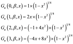 (6)
(6)
Figure 4 illustrates the time representation of the first four orders of modified Gegenbauer functions with β = 1.
Figure 5 shows the corresponding power spectrum densities (PSD).
3.2. The Modified Hermite Functions
The Modified Hermite functions have been proposed by Ghavami, Michael and Kohno [12] for use in a multi- user communication system. These functions are defined in the interval
 by:
by:
 (7)
(7)
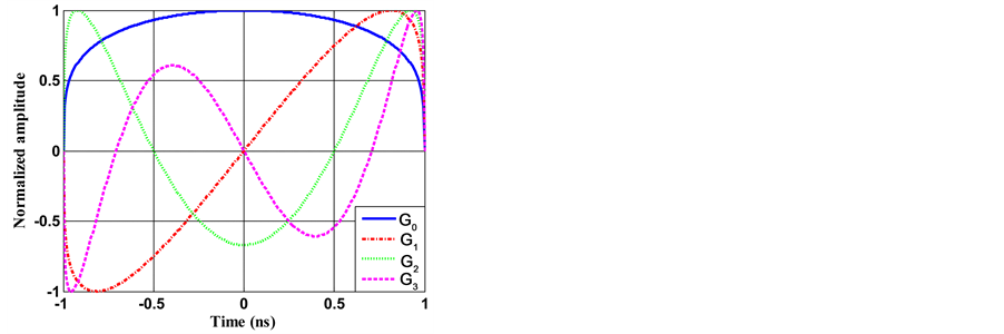
Figure 4. Modified Gegenbauer functions of orders n = 0, 1, 2 and 3.
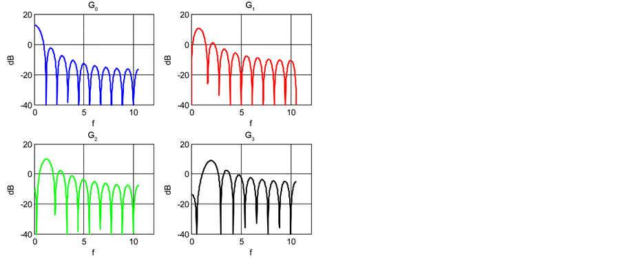
Figure 5. PSD of Gegenbauer functions.
where n represents the function order number.
The first four order functions, including order 0, are given by Equations (8) for the time domain.
 (8)
(8)
The first four Hermite time functions (n = 0 to 3) are presented in Figure 6.
Their widths are normalized to 1 ns, the truncation being performed so that at least 99% of energy is kept for the fourth order function. The vertical units are chosen so that the energy of all functions is equal to unity.
Figure 7 shows the corresponding power spectrum densities (PSD).
In order to choose the most appropriate waveform for the radar function, we compare by simulations in the first approach, the autocorrelation functions of the different waveforms. Then, experimental measurements are performed using laboratory test bench developed with real signals. The results of these simulations are detailed in the following paragraph.
3.3. Simulation Results
To evaluate the UWB radar performance using different types of waveforms, common criteria was defined. At the receiver, this criteria relies on the dynamic D, as shown in Figure 8, corresponding to the difference between the maximum of the auto-correlation signal and the highest secondary lobes. The dynamic is taken here from the

Figure 6. Hermite functions, orders n = 0 to 3.
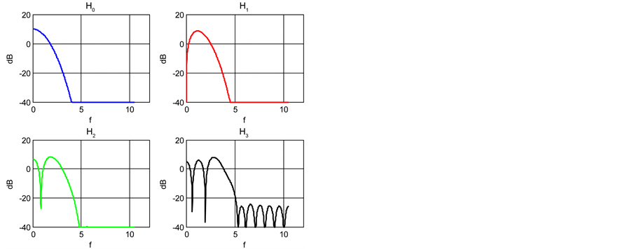
Figure 7. PSD of Hermite functions.

Figure 8. Definition of the dynamique.
absolute value of the auto-correlation function, as the difference between the maximum of the main lobe and the maximum value in the other lobes, if they exist (otherwise, this is assumed equal to 0). This corresponds to a linear receiver followed by threshold detection. The peak width is defined as the width (number of samples) between the −3 dB points of the autocorrelation function [13] .
The efficiency is defined as the ratio between the dynamic D and the peak width L, the higher this ratio is, better is the performance of the radar. Indeed, this ratio (D/L) reflects exactly the performance required for radar functionality that is a good dynamic (maximum D) and good precision (minimum peak width L) [11] .
In the following paragraphs, the efficiency for different orders of Gegenbauer and Hermite polynomials will be compared. After a first stage, among hermite and gegenbauer polynomials, we select the orders that give the best performance for the radar detection functionality according to the best ratio between the dynamics and peak width. In the second stage, we compare the autocorrelation function results obtained using, on the one hand those selected previously and on the other, using the Gaussian and monocycle pulses.
The autocorrelation functions of the first four Gegenbauer functions (G0 to G3, with β = 1), first four Hermite functions (H0 to H3), Gaussian pulse and monocycle pulse have been computed and summarized in Table 1. The dynamics, peak width and the efficiency figures have been then deduced there from. The results are given in Table 1.
Considering the relationship between the dynamic and width of the correlation peak, these comparisons show the highest efficiency among Gegenbauer functions belongs to the order 3 (G3). For Hermite functions, order 1 (H1) is the best.
For reference, the autocorrelation functions for G3, H1, Gaussian and monocycle pulses are given in Figure 9.
Finally, as seen in Table 1, from efficiency point of view, the third order Gegenbauer function seems to be the best, followed by the monocycle pulse, the first order of Hermite function and the Gaussian pulse.
In order to validate these simulation results, experimental tests are performed with these different waveforms. The results of these tests are detailed in the following paragraph.
4. Experimental Results
In this section, we will compare the results obtained by experimentation. First experimentations are performed in an anechoic chamber or very low noise environment, in order to isolate the effects of the equipment and environment. Other experimentations are performed in real conditions, in outdoor environment. Several tests are done using different obstacles (car, pedestrian, metal plate (1 m2), wooden plate (1 m2), motorway barrier etc.) in order to evaluate the performance of the UWB radar technology.
According to equipments, waveforms are generated using a UWB pulse generator with a sampling frequency of 20 G samples/sec. The receiver includes a direct sampling analyzer with 12 GHz bandwidth, 40 G samples/ sec sampling rate and 8 bits precision. Two “Vivaldi” antennas are used for emission and for measurements
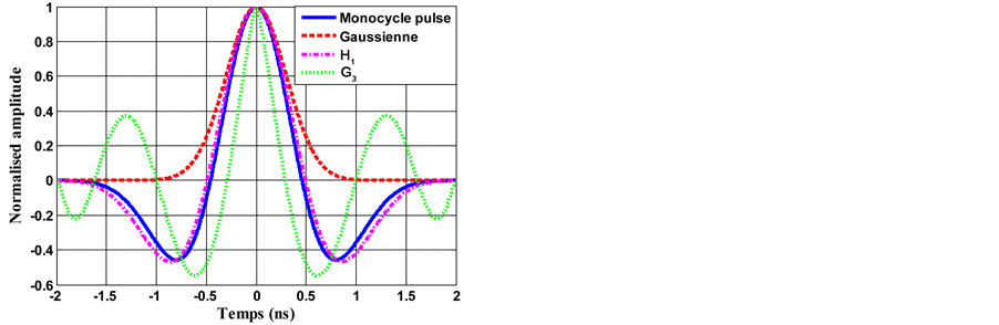
Figure 9. Comparison of G3, H1, Gaussian and monocycle pulses autocorrelation functions.

Table 1. Efficiency for the studied waveforms.
( Picture 1 ). This antenna has a gradual opening with periodic patterns and allows a gradual passage of the line (or guide) to free space, like a horn antenna. “Vivaldi” antennas are often wideband or double band. They operate in the frequency band from 700 MHz to 18 GHz. An example of the frequency response of a “Vivaldi” antenna is given in the Figure 10.
The transmitter/receiver configuration is presented in Figure 4. The radar sends ultra short pulses generated by UWB Generator through the “Vivaldi” transmitting antenna. After reflection from the obstacle, the received signal is correlated with the reference signal. The peak correlation is evaluated by the method of detection threshold and the distance from the source to the obstacle is deduced. To calculate the distance between the radar and the obstacle, we measure the time delay ΔT between the transmission and reception (Figure 11). This distance is given by Equation (9), where c represents the speed of light:
 (9)
(9)
To determine the target position, the received signal is correlated with reference signal. This reference signal is obtained after passing through the two antennas placed in front of one another (face to face). Thus, we consider effects of derivation and attenuation due to antennas without channel propagation effects. The target position is then calculated using the threshold detection method.
4.1. Performances Obtained Using Different Waveforms
In this section, in order to compare only waveforms, the signals are taken without any target; therefore, this situ-

Figure 10. Frequency response of an antenna Vivaldi.

Figure 11. Time delay between the emitted pulse and received echo.
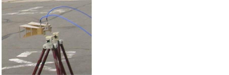
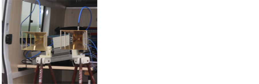
Picture 1. Vivaldi antennas used.
ation corresponds to the leakage between the transmission and reception antenna circuitry. These signals repre- sent the theoretical waveforms presented in previous sections, taking into consideration the effects of transmission and reception antennas.
As for the comparison by simulation, the autocorrelation functions of Gaussian, monocycle pulses and the first four orders of Gegenbauer and Hermite functions, have been computed. We calculated for each waveform the dynamic, the autocorrelation peak width and the relationship between these parameters (efficiency). The results are summarized in the following table.
The values obtained are close to those obtained from the theoretical simulations and presented in Table 1. The differences may be explained by the quantization of waveforms in the generator and the differences in the transmission of their spectra by the antennas and their associated circuitry.
We can see that the highest efficiency among Gegenbauer functions belongs again to the order 3 Gegenbauer function (G3). For Hermite functions, order 1 (H1) is again the best. Finally, from efficiency point of view, the third order Gegenbauer function seems to be the best, followed by the monocycle pulse, the first order Hermite function and the Gaussian, as seen in Table 2. This confirms the previous results obtained by simulations.
For comparison purposes, experimental autocorrelation functions obtained using G3, H1, Gaussian and monocycle pulses are given in Figure 12, the simulated ones have been presented in Figure 9.
We notice some distortions with respect to the theoretical (simulated) correlations and, particularly, some pulse broadening, different for each waveform. However the largest difference may be seen on the autocorrelations of the Gaussian pulse, which is the only waveform whose spectrum presents a DC component, not transmitted by the antennas. Some kind of derivation occurs and the correlation of the launched Gaussian waveform becomes somewhat similar to that of the monocycle waveform.
Considering the complexity of implementation, monocycle pulse is placed in the first position among the waveforms best suited for this radar system in the case of a single user or a single radar system. However, in a real environment, we must take into account the existence of several UWB radars in the same propagation channel. Using a simple waveform (Gaussian or monocycle pulse) is not appropriate in a multi-user case.
To avoid interference between users, the use of UWB orthogonal polynomials (Hermite and Gegenbauer), is a way to ensure multiple access. This method consists in associating, to each radar, a different waveform for a limited number of radar on the same road.

Figure 12. Experimental comparison G3, H1, Gaussian and monocycle pulse autocorrelation functions.
Table 2. Experimental efficiency for studied waveforms.
The coding of these waveforms emitted by each user is another way to realize multiple access. In fact, a distinctive code assigned to each user, the encoding is done by multiplying each bit of code by the UWB pulse as it is done in the CDMA (Code Division Multiple Access). This method increases system performance and reduces interferences between several users due to the double orthogonality it offers. These different orthogonal waveforms have also shown their great usefulness in multi-sensor radar systems. So, for each radar sensor in the same system, we associate a different waveform. This method helps distinguish the information from each sensor.
4.2. Experiments in Real Conditions and Outdoor Environment
In this paragraph, different targets or obstacles are placed at different distances in front of the radar and measured distances using each type of these waveforms (G3, H1, Gaussian, monocycle), will be evaluated and compared.
The first studied obstacle is a metal plate placed at 1.5 m from radar. The experiments were performed in the anechoic chamber. The autocorrelation results calculated for these waveforms are shown in Figures 13-16.
For these four waveforms, we observe that the level of the correlation peaks is very distinct according to noise level.
Based on this finding, we decide to classify the waveforms according to the precision of the radar to target distance measurement. The results of distance calculation are summarized in Table 3.

Figure 13. Correlation result using monocycle pulse.

Figure 14.Correlation result using Gaussian pulse.

Figure 15. Correlation result using order 3 of Gegenbauer function.

Figure 16. Correlation result using order 1 of Hermite function.
Table 3. Distance measurements using a metal plate at 1.5 m.
Considering the precision of measured distance, the monocycle pulse appears more suitable for radar application with the metal plate target.
On one hand, the DC component of following waveforms (monocycle pulse, Gegenbauer and Hermite functions with odd orders), is zero, and this feature ensures lesser distorsion by the antennas (particularly lower differentiation). The DC component of the Gaussian pulse is not zero and this explains its poor performance.
On the other hand, as seen in Figure 1 and Figure 2, the Gaussian and monocycle pulses spectra are monotonous (single band), and therefore less distorded by the antennas (whose response is wideband, but not ultra wideband) than the G3 pulse and (to a lesser extent) H1 pulse, whose spectra are multiband in nature, as shown in Figure 5 and Figure 7. The performance of the Gegenbauer and Hermite functions is therefore reduced with respect to that of monocycle pulse. Moreover, considering the realisation complexity (and cost), monocycle pulse could be the best choice or a good trade-off for the radar function, the corresponding generators being the most easily commercially available at reasonable price.
To evaluate the performance of this UWB radar in real environment, with our laboratory prototype or test bench, we performed several tests using different scenarios. In this paragraph we present the correlations results based on two types of obstacles placed at a fixed distance from the radar.
The obstacles used for outdoor experiments are a wooden plate of 1 m2 area lying at 2 m from the radar and a car placed at 1.5 m. The car has a better reflection coefficient than the wooden plate. The lower noise level obtained by the signals received from reflections by the car confirms this.
Figure 17 presents, as an example, the results of correlation for these two types of obstacles using the monocycle pulse.
Now we compare the calculated distances obtained from the four waveforms, using the car placed at 1.50 m from UWB radar. The results are shown in Table 4.
The comparison between the calculated distances for the four waveforms, using the wooden plate placed at 2 m far from radar, shown in Table 5, is also performed.
Considering the precision of calculated distance, the monocycle pulse gives again the result closest to the real one in the outdoor experiments. So it is more appropriate for our UWB radar application.
Table 4. Measured distances for car at 1.5 m.
Table 5. Measured distances for wooden plate.

 (a) (b)
Figure 17. Correlation result using the monocycle pulse (a) Car; (b) Wooden plate.
5. Conclusions
In this paper we present the UWB technology and show its utility for radar application. In addition, UWB allows the use of waveforms as narrow pulses more suitable for radar detection and avoiding interference between different users.
Different UWB waveforms are presented and several comparisons among them are performed in order to choose the most suitable one for UWB radar functionality.
To make a choice, we rely on the comparison between autocorrelation functions of these waveforms with simulation and experimental measurements. These studies show that the monocycle pulse is the best candidate in terms of efficiency (ratio dynamics to peak width), implementation complexity and distance resolution reached, followed by the third order Gegenbauer and the first order Hermite functions, for a single user. The performance could be enhanced using truly ultra-wideband antennas.
Comparing to classical UWB waveforms, Gegenbauer and Hermite functions also allow multiple accesses in the case of a limited number of users and offer a double orthogonality if associated with codes in the case of high number of users. This double orthogonality allows better performances to reduce interference between users.
Current work aims to study the feasibility of UWB radar processing in real time. The real time factor requires having a correlation result, therefore distance, at each repetition period of emission, which is about hundreds nanoseconds. In addition, each sample of the correlation must be calculated at the speed of data reception. This is possible only using programmable logic circuits like FPGA (Field Programmable Gate Array) that have the characteristics of flexibility, reconfigurability, with many potential applications in embedded systems.
The problem of sampling limitations and the speed at which currently available FPGAs run shall be considered. Suitable alternative solutions will be proposed to reduce the complexity of the receiver in order to implement a real time receiver based on FPGA platform.
References
- http://www.fcc.gov/Bureaus/Engineering_Technology/Orders/2002/fcc02048.pdf
- Haartsen, J.C. (2000) The Bluetooth Radio System. IEEE Personal Communication, 7, 28-36.
- Elbahhar, F., Rivenq-Menhaj, A., Rouvaen, J.M. and Heddebaut, M. (2001) Inter-Vehicle Communication Based on Ultra-Wide Band Technique. Proceedings of Telecom, Casablanca, March 2001, 58-61.
- Damien Scherrer, D. (2007) OFCOM Infomailing No. 8. Federal Office of Communication, 11-15.
- (2006) The 28 eSafety Recommandations. eSafety Compendium, 44-45.
- Elbahhar, F., Rivenq-Menhaj, A., Rouvaen, J.M., Deloof, P. and Boukour, T. (2001) An Ultra-Wide Band System for Vehicle-to-Vehicle Communication. Proceedings of Intelligent Transportation System Conference, Sydney.
- Lamari, A. (2007) Conception and Modeling of a Multi-User Communication System Based on Ultra Wide Band Technology. Ph.D. Thesis, University of Valenciennes and Hainaut Cambrésis.
- Elbahhar, F., Rivenq-Menhaj, A. and Rouvaen, J.M. (2005) Multi-User Ultra Wide Band Communication System Based on Modified Gegenbauer and Hermite Functions. Wireless Personal Communications, 34, 255-277. http://dx.doi.org/10.1007/s11277-005-3922-2
- Erseghe, T. (2002) Ultrawide Band Pulse Communications. Ph.D. Dissertation, University of Padova, Italy.
- Carlberg, T. (2000) Analysis of Ultra Wide Band (UWB) Technology for Indoor Geolocation and Physiological Monitoring System. Master Thesis, Chalmers University of Technology, Sweden.
- Sakkila, L. (2009) Study and Implementation of an Ultra-Wide-Band Radar Aimed to Obstacle Detection and Recognition in Road Environments. Ph.D. Thesis, University of Valenciennes and Hainaut Cambrésis.
- Lachlan, B.M., Ghavami, M. and Kohno, R. (2002) Multiple Pulse Generator for Ultra-Wideband Communication Using Hermite Polynomial Based Orthogonal Pulses. IEEE Conference on Ultra Wideband Systems and Technology.
- Sakkila, L., Rivenq, A., Tatkeu, C., Elhillali, Y., Boukour, F. and Rouvean, J.-M. (2010) Comparison of Classical and Orthogonal UWB Waveforms for Radar Applications. 6th International Colloquium on Signal Processing & Its Applications CSPA, Malacca, 21-23 May 2010.
NOTES

*Corresponding author.