Wireless Engineering and Technology
Vol.2 No.2(2011), Article ID:4543,10 pages DOI:10.4236/wet.2011.22009
Reconfigurable Microstrip Double-Dipole Antennas for Personal Wireless Communications
![]()
Department of Computer Engineering, Jackson State University, Jackson, USA.
Email: Abdelnasser.eldek@jsums.edu
Received November 2nd, 2010; revised February 24th, 2011; accepted February 28th, 2011.
Keywords: Reconfigurable Antennas, Dipole, Wideband, Multiband
ABSTRACT
In this paper, a number of reconfigurable antennas are designed to support multiband and wideband wireless applications in different frequency bands in the range between 1 GHz and 6 GHz. The proposed designs consist of microstrip-fed two dipoles through simplified balun. By controlling the lengths of the dipoles by connecting or disconnecting slots, we are able to change the antenna operating frequency as well as the operation mode. Two modes are supported by all of the proposed antennas: Multiband and Broadband modes.
1. Introduction
As communication devices become smaller due to greater integration of electronics, the antenna becomes a significantly larger part of the overall package volume. This results in a demand for similar reductions in antenna size. However, reducing antenna size without significantly impacting gain and efficiency is a challenging task. As integration increases, a single antenna is often required to support two or more of the many wireless services across a broad frequency range. Multiband, wideband and reconfigurable antennas are being developed to meet this need [1]. Multi-band and wideband antennas require complicated filters with stringent requirements to improve their out-of-band noise-rejection performance. These filters, moreover, are generally bulky and expensive. In contrast, frequency-reconfigurable antennas have great potential for reducing production cost and offer better out-of-band noise rejection [2]. In addition, compared to multiband and broadband antennas, reconfigurable antennas offer the advantages of compact size, similar radiation pattern for all designed frequency bands, efficient use of electromagnetic spectrum and frequency selectivity useful for reducing the adverse effects of co-site interference and jamming [3]. Dual frequency reconfigurable microstrip antennas can offer additional advantages of frequency reuse for doubling the system capability and polarization diversity for good performance of reception and transmission or to integrate the receiving and transmitting functions into one antenna for reducing the antenna size [4,5].
Microstrip antennas are attractive candidates for reconfigurable antenna technology because of their inherent low profile, light weight, low cost, and ease of fabrication and installation [2,6-13]. Number of attractive reconfigurable antenna designs were presented in [2] with the objective of reduction of the number of MEMs utilizing antenna symmetry to decrease the cost. The concept of a frequency-reconfigurable rectangular ring slot antennas fed by slotlines or CPW is presented in [7]. A reconfigurable patch antenna is obtained in [8] by inserting slits at the non-radiating edges of the patch. A reconfigurable Yagi antenna is presented in [9] to operate at 2.4 and 5.78 GHz for wireless communications. A reconfigurable slot dipole antenna was presented in [10] in the X-band. Patch antenna with polarization diversity using switchable L-shaped slots is presented in [11]. A reconfigurable dipole antenna with harmonic trap was presented in [12] where the operating frequency is controlled by a reconfigurable dipole length, while the higher-order modes are eliminated using a reconfigurable l/4 open circuit stub. A compact multiband antenna has been redesigned to be reconfigurable with embedded switches to allow selective addressing of these bands [13].
In this paper, three microstrip-fed double-dipole antenna designs [14-16] to support multi-band, wideband, and single-band operation modes are presented for personal wireless communications. The reconfiguration for the microstrip antennas is carried out by connecting or disconnecting (switching on or off) appropriate rectangular strips to model the MEM switches. The shape and number of these strips along with the switching state and position is used to control the operating frequency of the antenna without changing the feeding mechanism. The antennas’ geometries and their results will be explained in the next two sections. The full-wave electromagnetic simulations and analysis for the presented antenna are performed using the commercial computer software package Ansoft High Frequency Structure Simulator (HFSS) [17], which is based on the finite element method. Measurements of the return loss and radiation patterns are also conducted to verify the simulation results and demonstrate the feasibility of the proposed configurations.
2. Antennas’ Geometries and Parametric Study
Three double-dipole antennas were designed for different frequency bands and depicted in Figure 1. The double-dipole antenna consists of two dipoles with similar or different lengths depending on the required operating frequencies. A simplified balun is used to feed the dipoles. In each dipole, the left half is printed on the top substrate layer and fed by a microstrip line, while the right half is printed on the bottom layer and connected to the truncated ground plane.
The length of the dipole is approximately half the wavelength at the operating frequency, while its distance from the truncated ground plane is quarter wavelength for the best performance. Thus, if the antenna is required to operate at a lower frequency (fL) and a higher frequency (fH), then the shorter dipole will be closer to the ground plane. In this case, the antenna will operate at multiple bands. A broadband design can be achieved by making the longer and the shorter dipoles to resonate at closer frequencies. This can be achieved by reversing the positions of the two dipoles. With the contribution of the coplanar strip (CPS) line length to the antenna length, the difference between their lengths become small, and the two operating bands will be close and can merge in one relatively wide frequency band.
The next step is to merge these two modes in one so that the length of the closer dipole is controlled by the lower operating frequency in the wideband mode, and the length of the second dipole is controlled by the higher operating frequency in the multiband mode. Next, a proper matching circuit between the two dipoles is designed to eliminate the mutual effect between the two modes. Therefore, the shape of the CPS connecting the two dipoles is modified as needed by the design to obtain the required modes. Finally, when adding the ground plane, it will have an effect on the performance; therefore, the last step is to shape the ground plane to reduce this effect as shown in Figure 1. A smooth transition from the microstrip line mode to the two CPS line mode is used for this purpose.
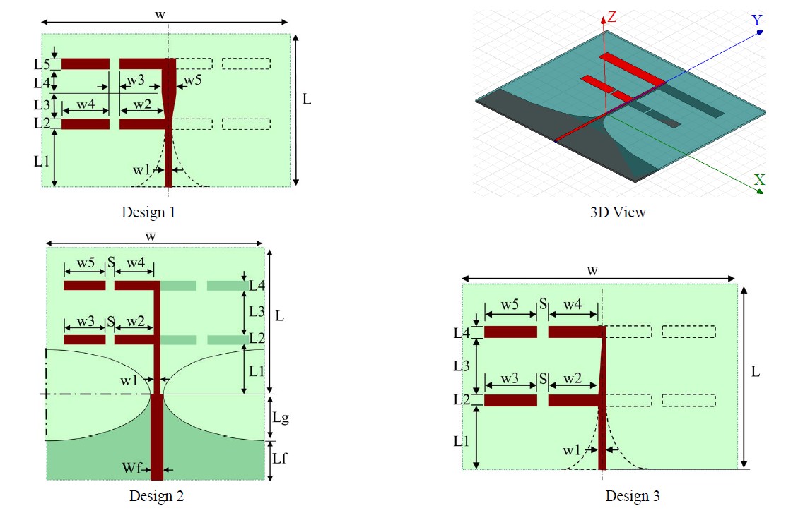
Figure 1. Antennas’ geometries and paramters.
Parametric study is performed on each antenna and depicted in Figures 2 to 11 for Design 1. This study is done in the multiband mode to know the effect of each parameter, and select the best dimensions, and tune the antenna to obtain the best bandwidth in the broadband mode without affecting the multiband mode. The dimensions of the three designs resulted from the parametric study are shown in Table 1.
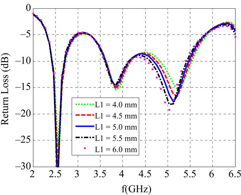
Figure 2. Effect of L1.
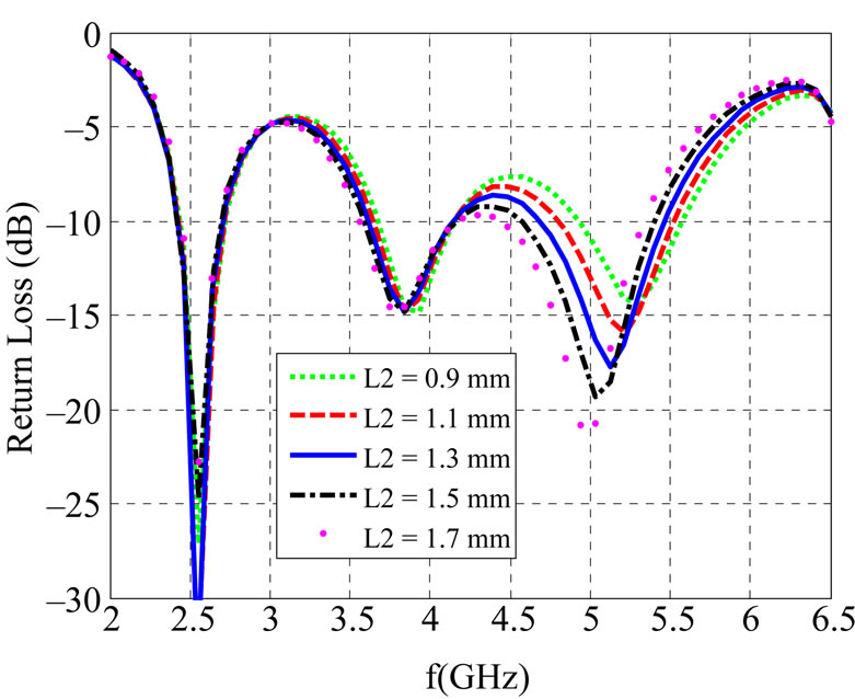
Figure 3. Effect of L2.
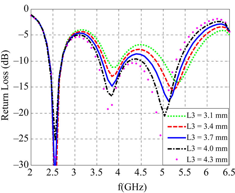
Figure 4. Effect of L3.
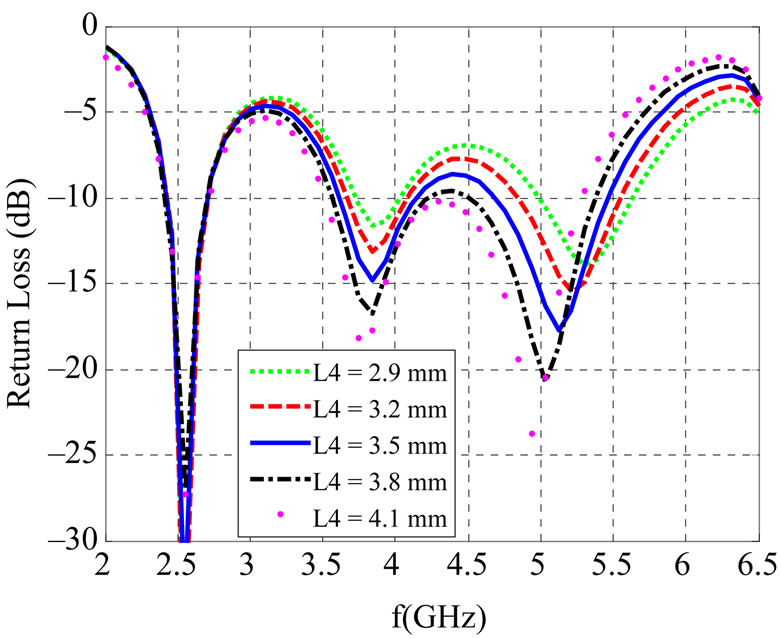
Figure 5. Effect of L4.
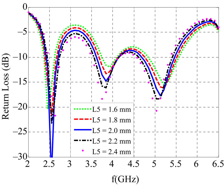
Figure 6. Effect of L5.
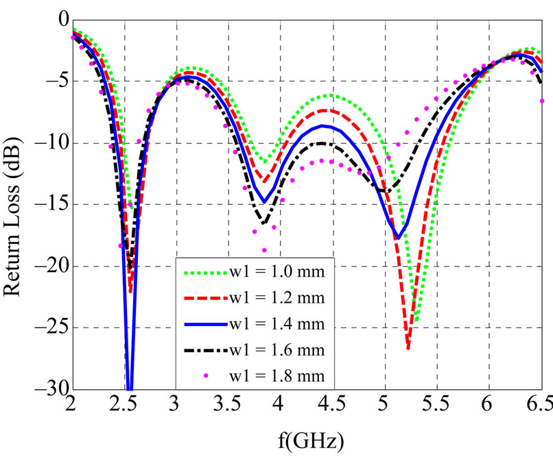
Figure 7. Effect of w1.
3. Results
The return loss and radiation patterns are computed using Ansoft HFSS for Designs 1, 2 and 3. The reconfiguration is carried out by connecting or disconnecting appropriate rectangular strips to model the MEM switches. The rectangle width is “S” and its height is the same like the
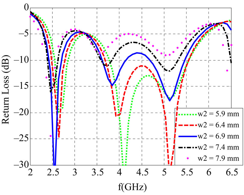
Figure 8. Effect of w2.
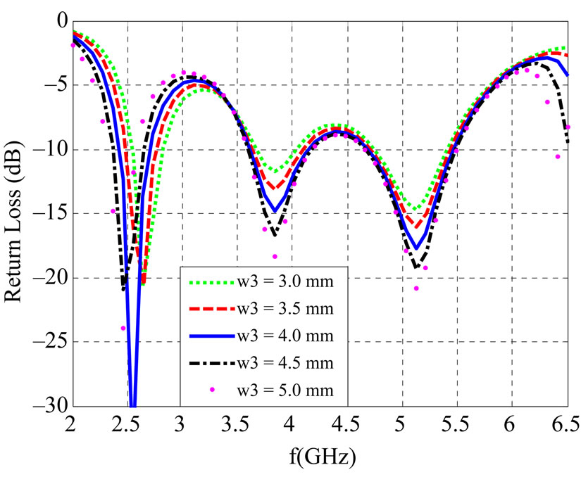
Figure 9. Effect of w3.
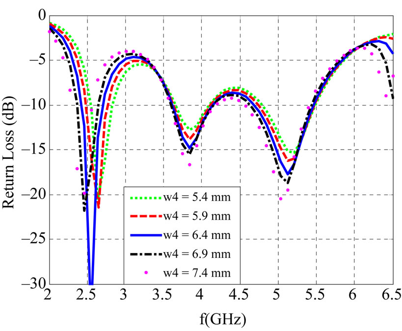
Figure 10. Effect of w4.
strip on which Pin diode or MEMs can be installed. Since we have four switches, we can create 16 cases starting from Case 0000 when all switches are open, to Case 1111 when all switches are closed. However, only 10 different combinations are considered after excluding the similar cases such as 0010 and 0001.
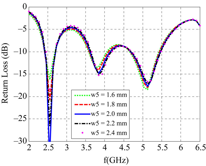
Figure 11. Effect of w5.
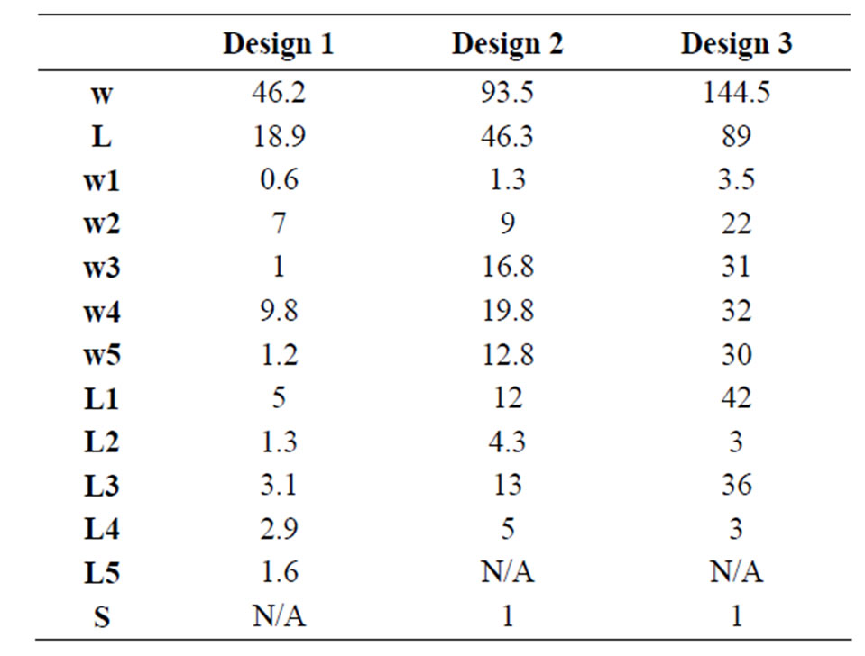
Table 1. Dimensions (mm) of the proposed designs.
Figure 12 shows the multiband (0011) and broadband (1100) cases in addition to the cases when all switches are ON/OFF (0000 and 1111). These cases are the symmetrical cases where S1 and S3 are the same as S2 and S4, respectively. The operating bands of the three designs in this figure are summarized in Tables 2, 3, and 4 for Designs 1, 2, and 3, respectively. With only four cases out of ten, Design 1 covers 90% of the band between 2.22 and 6.28 (95% bandwidth), Design 2 can operate in 90% of the band between 1.64 and 3.2 (64% bandwidth), and Design 3 also covers almost all the band between 0.83 and 2.34 (95% bandwidth). In the broadband Case, the three Designs provide from 22% to 56% bandwidth. Figure 13 shows some unsymmetrical cases which show that we still can make these antennas operate at other frequencies.
These results show many advantages for these designs. First, we can switch between different frequency bands without changing the antenna. Second, we can also change between multi-band and broadband modes. In addition, the overall antenna operating bandwidth is at least 1.7 times the maximum bandwidth of all cases.
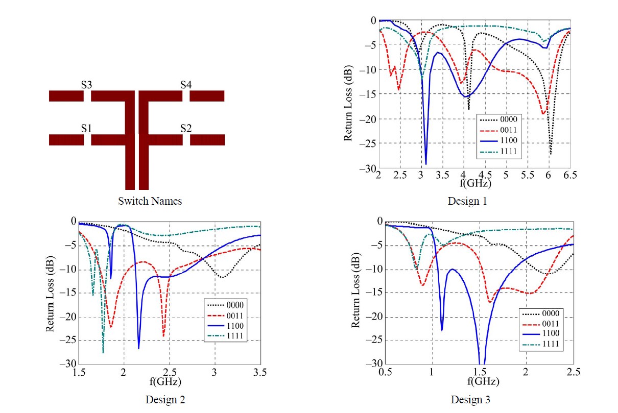
Figure 12. Return Loss (dB) for the symitrical cases.

Table 2. Operating frequency bands and bandwidth for Design 1 in the symitrical cases.

Table 3. Operating frequency bands and bandwidth for Design 2 in the symitrical cases.
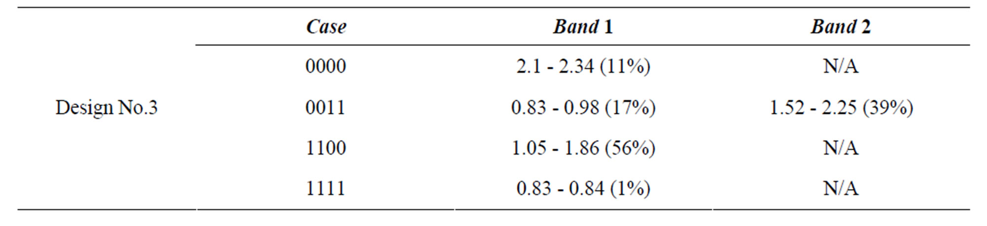
Table 4. Operating frequency bands and bandwidth for Design 3 in the symitrical cases.

Figure 13. Return Loss (dB) for the unsymitrical cases.
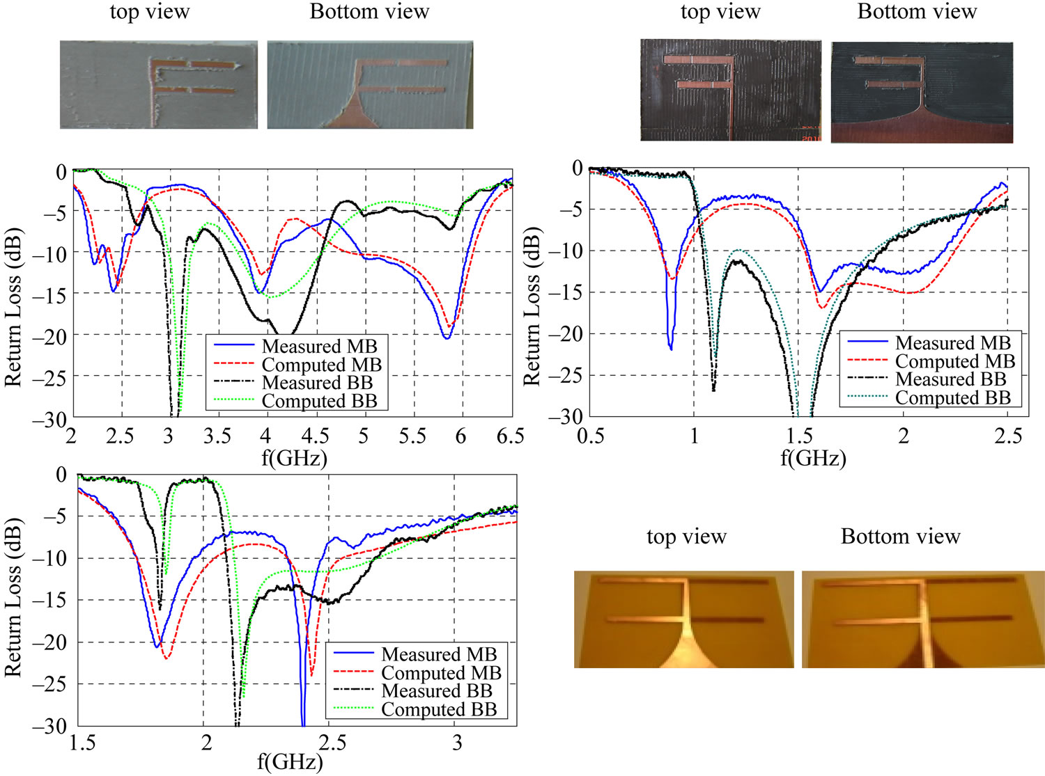
Figure 14. Measured and computed return loss and antenna prototypes.
Prototypes from the three designs are fabricated using LPKF milling machine. The return loss is measured using vector network analyzer for the different reconfigurable cases. Figure 14 shows a good agreement between the measured and computed results in the multi-band (MB) and broadband (BB) modes. Finally, the radiation patterns are computed and measured using anechoic chamber. Figures 15 to 17 show the co-polarized fields at selected resonance frequencies for Designs 1, 2 and 3, respectively, for the MB and BB cases. The lower half is cropped because of the symmetry. An acceptable match is obtained between the measured and computed results. Currently, we are in the process of sending antenna prototypes to specialized for integrating reconfigurable enabling technology such as MEMs in these designs.
4. Conclusions
Three novel reconfigurable microstrip antenna designs are presented for wireless communications applications. The proposed antennas are combination of two dipole antennas of similar and different lengths. By changing the dipoles’ lengths, we were able to change the antenna
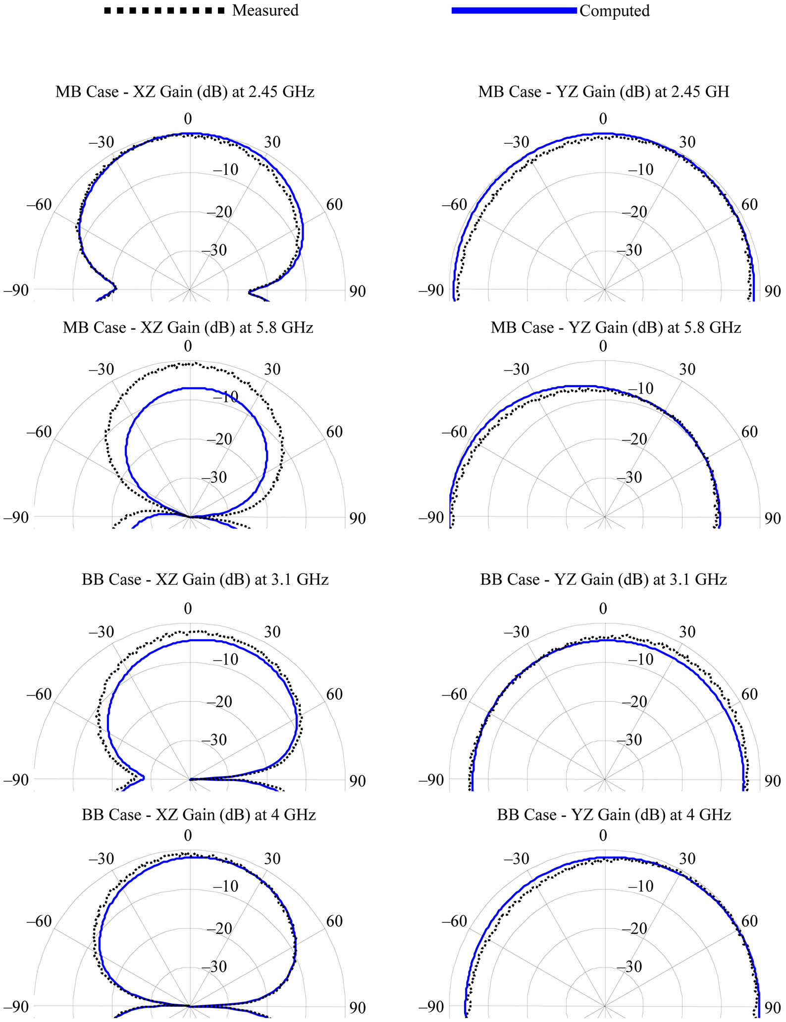
Figure 15. Radiation Patterns for Design 1 in multiband and broadband modes.
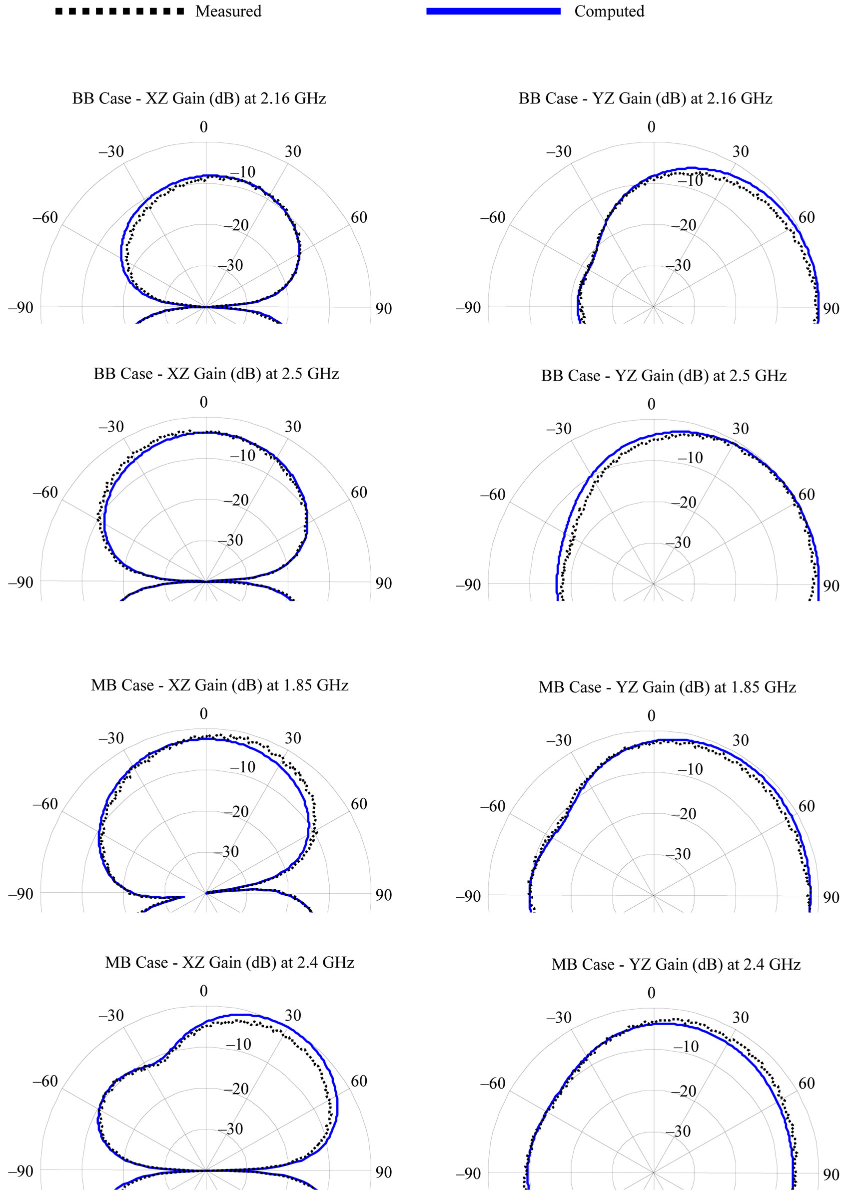
Figure 16. Radiation Patterns for Design 2 in multiband and broadband modes.
operating frequency as well as the operation mode. The antenna is merging two operating modes: Multi-band and Broadband in a single design. The presented designs cover different frequency bands: 0.83 - 2.34 GHz, 1.64 - 3.2 GHz, and 2.22 - 6.28 GHz. A wide overall bandwidth of 95% was obtained and a wide single case operating
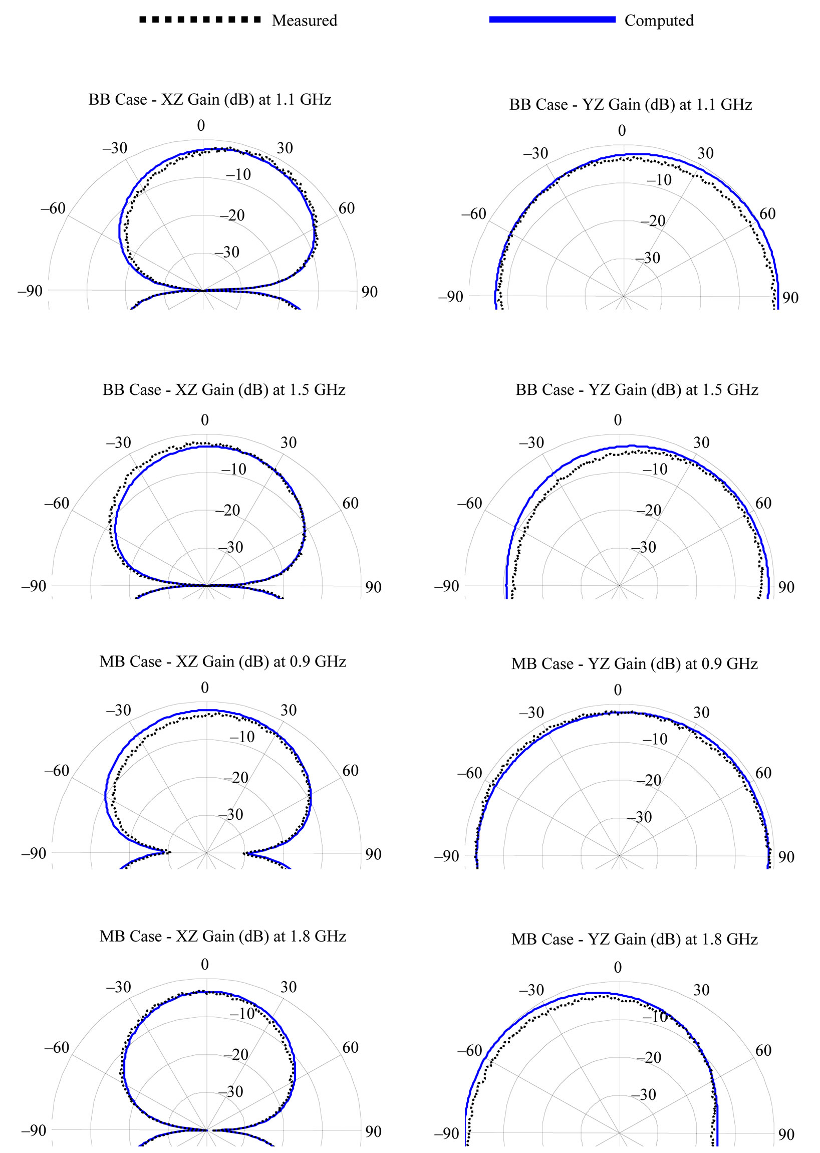
Figure 17. Radiation Patterns for Design 3 in multiband and broadband modes.
bandwidth of 56% was also provided.
5. Acknowledgements
The authors would like thank the Air Force Research Laboratory (AFRL)—Minority Leaders Program (MLP), and Clarkson Aerospace Corp for funding this research through contract number FA8650-05-D-1912. Many thanks are also to Mr. William Munn and Mr. Christopher Munn from Jackson State University for their help in building the proposed antennas.
REFERENCES
- C. B. Dietrich, Jr., R. M. Barts, W. L. Stutzman and W. A. Davis, “Trends in Antennas for Wireless Communications,” Microwave Journal, vol. 46, no. 1, January 2003, p. 22.
- S. N. Yang, C. N. Zhang, H. K. Pan, A. E. Fathy and V. K. Nair, “Frequency Reconfigurable Antennas for Multiradio Wireless Platforms,” IEEE Microwave Magazine, vol. 10, no. 1, February 2009, pp. 66-83. doi:10.1109/MMM.2008.930677
- D. Peroulis, K. Sarabandi and P. B. K. Katehi, “Design of Reconfigurable Slot Antennas,” IEEE Transactions on Antennas and Propagation, Vol. 53, No. 2, 2005, pp. 645- 654. doi:10.1109/TAP.2004.841339
- S. V. Shynu, G. Augustin, C. K. Aanandan, P. Mohanan, and K. Vasudevan, “A Reconfigurable Dual Frequency Slot Loaded Microstrip Antenna Controlled by Pin-Diodes,” Microwave and Optical Technology Letters, vol. 44, No. 4, 2005, pp. 374-376.
- S. V. Shynu, G. Augustin, C. K. Aanandan, P. Mohanan, and K. Vasudevan, “Design of Compact Reconfigurable Dual, Frequency Microstrip Antennas Using Varactor Diodes,” Progress in Electromagnetics Research, Vol. 60, 2006, pp. 197-205. doi:10.2528/PIER05120101
- W. H. Weedon, W. J. Payne and G. M. Rebeiz, “MEMsSwitched Reconfigurable Antennas,” IEEE Antennas and Propagation Society International Symposium, Boston, vol. 3, 8-13 July 2001, pp. 654-657.
- K. C. Gupta, J. Li, R. Ramadoss and C. J. Wang, “Design of Frequency-Reconfigurable Rectangular Slot Ring Antenna,” IEEE Antennas and Propagation Society International Symposium, Salt Lake City, vol. 1, 16-21 July 2000, p. 326.
- S. Xiao, B. Z. Wang and X. S. Yang, “A Novel Frequency-Reconfigurable Patch Antenna,” Microwave and Optical Technology Letters, vol. 36, no. 4, February 2003, pp. 295-297. doi:10.1002/mop.10746
- P. F. Wahid, M. A. Ali and B. C. Deloach, “A Reconfigurable Yagi Antenna for Wireless Communications,” Microwave and Optical Technology Letters, vol. 140, no. 2, July 2003, pp. 140-141. doi:10.1002/mop.10997
- A. A. Eldek, A. Z. Elsherbeni, C. E. Smith and K. F. Lee, “Wideband Slot Antennas for Radar Applications,” Proceedings of IEEE Radar Conference, Huntsville, 5-8 May 2003, pp. 79-84.
- S. Raghavan, T. Shanmuganantham and M. S. K. Kumar, “Reconfigurable Patch Antenna with Switchable L-Shaped Slots for Circular Polarization Diversity,” Microwave and Optical Technology Letters, vol. 50, no. 9, September 2008, pp. 2348-2350. doi:10.1002/mop.23674
- A. Mirkamali, P. S. Hall and M. Soleimani, “Reconfigurable Printed-Dipole Antenna with Harmonic Trap for Wideband Applications,” Microwave and Optical Technology Letters, vol. 48, no. 5, May 2006, pp. 927-929. doi:10.1002/mop.21521
- C. N. Zhang, S. N. Yang, H. K. Pan, A. E. Fathy, S. El-Ghazaly and V. K. Nair, “A Reconfigurable Multiband Patch Antenna for Wireless Applications Using MEMS Switches,” Microwave and Optical Technology Letters, vol. 51, no. 8, August 2009, pp. 1892-1896. doi:10.1002/mop.24474
- F. Tefiku and C. A. Grimes, “Design of Broad-Band and Dual-Band Antennas Comprised of Series-Fed PrintedStrip Dipole Pairs,” IEEE Transactions on Antennas and Propagation, vol. 48, no. 6, 2000, pp. 895-900. doi:10.1109/8.865221
- A. A. Eldek, “Pattern Stability Optimization for Wideband Microstrip Antennas for Phased Arrays and Power Combiners,” Microwave and Optical Technology Letters, vol. 48, no. 8, August 2006, pp. 1492-1494. doi:10.1002/mop.21740
- A. A. Eldek, “Design of Double Dipole Antenna with Enhanced Usable Bandwidth for Wideband Phased Array Applications,” Progress in Electromagnetics Research, Vol. 59, 2006, pp. 1-15. doi:10.2528/PIER06012001
- Ansoft Corporation, “HFSS: High Frequency Structure Simulator Based on the Finite Element Method,” Version 12, 2008.