Smart Grid and Renewable Energy
Vol. 4 No. 3 (2013) , Article ID: 33403 , 9 pages DOI:10.4236/sgre.2013.43033
Regulation of the Excitation Reactive Power of the Asynchronous Wind Turbine at Variable Speed
![]()
1University Mohammed, Ecole Supérieure de Technologie OujdaSchool of Technology Oujda, Laboratoire de Génie Electrique et Maintenance LGEM,Laboratory of Electrical Engineering and Maintenance (LEEM), Oujda, Morocco; 2University Mohammed, National School of Applied Sciences, Oujda, Morocco; 3University of Picardie Jules Vern, Amiens, French.
Email: *ced_ouchbel@yahoo.fr, *szouggar@gmail.com
Copyright © 2013 Taoufik Ouchbel et al. This is an open access article distributed under the Creative Commons Attribution License, which permits unrestricted use, distribution, and reproduction in any medium, provided the original work is properly cited.
Received March 19th, 2013; revised April 20th, 2013; accepted April 29th, 2013
Keywords: Renewable Energy; Wind Energy; Modeling; Control of Reactive Power
ABSTRACT
This work focuses, initially, on modeling and simulating an isolated wind system in MATLAB/SIMULINK. And in the second part, it presents the simulation results of the wind system to start unloading and in resistive load, and the third part will discuss the strategy for adjusting the output voltage of the wind system to connect it to a rural operating load. The results show that in a dynamic environment where the wind speed and the load, changes abruptly, the voltage of the output is controlled at the desired value.
1. Introduction
In remote areas, the asynchronous wind turbines are the most widely used ones for the electricity generation. They, generally, do not produce reactive power, for this reason, the use of the capacitor banks connected in parallel to the terminals of the stator coils of the asynchronous generator, for the generation of the needed reactive power, is necessary.
This article is divided into three parts:
Firstly, from the experimental tests, we have modeled and simulated, in transient state, under MAT-LAB/ SIMULINK environment, an isolated wind system composed by: Turbine, multiplier, Shaft, self-excited asynchronous machine of 1.5 kw, static inverters AC-DC, LC filter, and resistive load [1-4].
Secondly, we have determined the shaft angular speed of the induction generator according to wind speed, the turbine parameters and the multiplier, the resistive torque and frictions [5].
In the third part and in taking account that the output voltage of the asynchronous generator varies with the sudden change of wind speed and load [3-6], we have developed a law and adaptive control for regulating the output voltage of the system at a constant value [6-10]. The adaptive control is based on the use of reactive power necessary to excite the asynchronous generator.
Finally, the simulation results obtained are discussed to show that the output voltage is exactly controlled at the desired value.
2. Modeling of the Isolated Wind System
In this part of this work, we modelled and simulated a system consisting of a wind turbine with blades of length R, involving an asynchronous generator with gearbox of speed gain M.
2.1. The Turbine Model
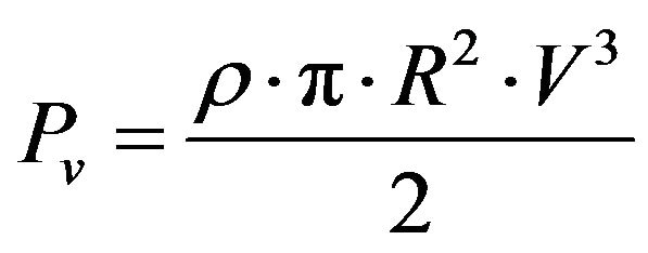
The power of the wind is defined by:
 (1)
(1)
where  is the air density, R is the blade length, and V the wind speed.
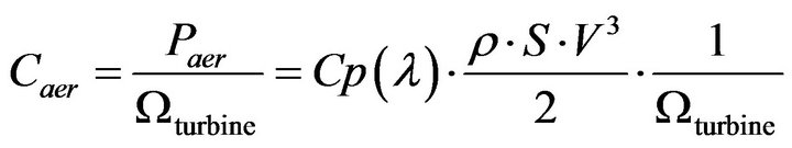
The aerodynamic power appearing with the rotor of the turbine is given by:
 (2)
(2)
Such as:  represents the aerodynamic performance of the wind turbine. The ratio speed
  is the relationship between the linear velocity of the blades and the speed of the wind
 (3)
(3)
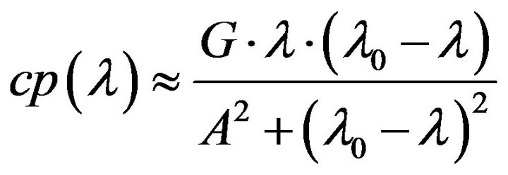
Where  is a mechanical rotation speed of the turbine, for the turbine used in this study, the reactive power coefficient
  is approached by the following formula [7]:
 (4)
(4)
Figure 1 shows the variation of the coefficient  (Equation (4)) as a function of lambda.
  By using the preceding equation we deduced the aerodynamic torque according to the Equation (5):
 (5)
(5)
2.2. Model of the Gear
The torque of the generator is given by Equation (6) and the mechanical speed appeared on the shaft of the generator given by the Equation (7).
 (6)
(6)
 (7)
(7)
M is the gear ratio.
2.3. Dynamic Equation of the Generator Shaft
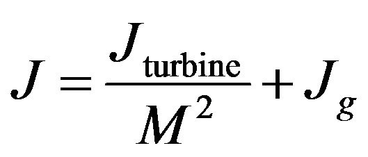 (8)
(8)
And
 (9)
(9)
 (10)
(10)
 (11)
(11)
where  is the mechanical torque,
  the electromagnetic torque produced by the generator and
  the viscous friction torque. The schematic model of the mechanical equation is given by Figure 2.
2.4. Model of the Self-Excited Induction Generator SEIG
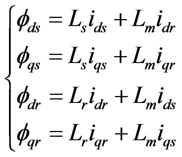
The classical electrical equations of the SEIG in the Park frame are written as follows:
 (12)
(12)
 are respectively the voltage and current output of the generator in the model of Park.
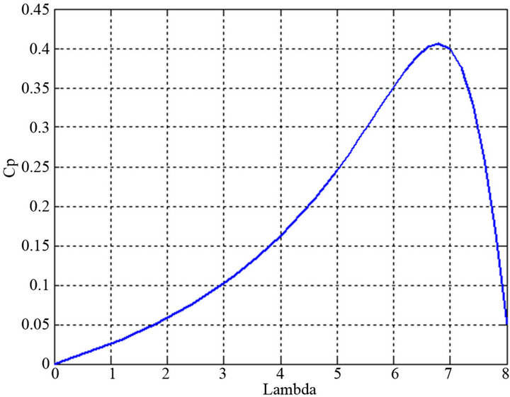
Figure 1. Evolution of the function .
.

Figure 2. Block diagram of the turbine.
 and
and  are respectively the resistance and inductances of the stator and rotor winding,
 is the main inductance and
  is the rotor speed, p is the number of pole pair.
 (13)
(13)
The electromagnetic torque is given by the following formula:
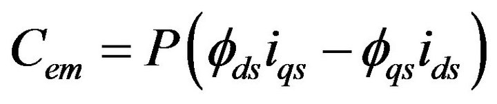 (14)
(14)
2.4.1. Steady-State Model
The Self-excited Induction Generator SEIG is modelled in the steady-state by using the equivalent diagram shown in the Figure 3:
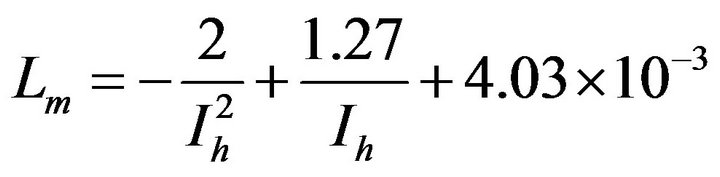
The linear model of SEIG considers that the magnetizing inductance is constant, which is not true, as it’s seen in the Figure 4, because the magnetic material used for manufacturing is not linear.
It is very essential to take into account the saturation effect of the magnetic circuit and of the variation of magnetizing inductance.
To approach the characteristics of the induction machine (All the experimental points Lm) by a mathematical function, we used an approximation method.
The experimental curve of the magnetic inductance is divided into three parts
For 
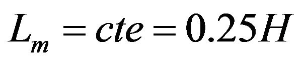
For 
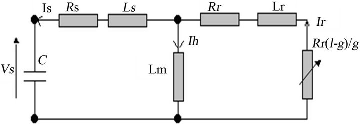
Figure 3. The Phase equivalent circuit of the SEIG.

Figure 4. Magnetizing inductance of the induction machine.
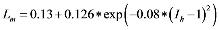
For 
2.4.2. Transient Model of SEIG
By taking into account the initial conditions for the process of self excitation, the transient state of (SEIG) is represented in the model of Park by the matrix according to:
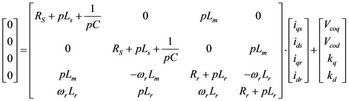
Kq and Kd are constant, they represent respectively the initial induced voltages of the d-axis and q-axis axes (d,q).
Vcqo and Vcdo are initial voltages of the capacitor bank on the two axes d and q.
From this matrix we have developed a mathematical model of the asynchronous generator that we use in the simulation of the wind system.
2.5. Simulation Results of Wind Systems
To simulate the wind system (SEIG and turbine), we used a machine wound rotor and a turbine of characteristics mentioned in Tables 1 and 2 respectively.
2.5.1. Start-Up with No Load
In this part of our work, we discuss the simulation results.

Table 1. Parameter of SEIG.
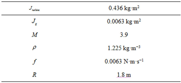
Table 2. Parameter of turbine.
Figure 5 illustrates the voltage of leadless starting of the SEIG versus time. The starting time is about 2.7 seconds for a wind speed and a capacity constants of 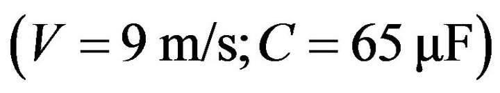 .
.
Also, we propose to simulate and analyze the behaviour of the system when the electrical (capacity, load) and the mechanical parameters (speed) vary, and to study the influence of the variation of each parameters on the stability and the performance of the installation.
Figure 6 illustrates the variation of the angular velocity on the generator shaft for various values of the wind speed. We observe that the mechanical speed varies proportionally with the wind speed.
Figure 7 shows the curves of RMS voltage Vs of a phase stator during the start-up period for different values of capacity. We note that the voltage changes for each value of the capacity.
Figure 8 shows the evolution of the RMS voltage (Vs) when the generator is driven empty and loaded gradually.
For different values of resistive loads, we traced the evolution of the output voltage in function of the time.
Figure 9 shows the curves of the RMS voltage (Vs) of a stator phase during the starting period for different values of the wind speed. We also obtained the same curves for each speed but with a time lag of starting of the machine and a change in the stability voltage. Thus the evolution of the electromagnetic torque generated by SEIG, exposed in the Figure 10, during the start-up period for a given capacity and wind speed, On the previous figures we have presented the typical results of simulation of RMS voltage at the system output (SEIG and turbine), its objective is to study the behaviour of the
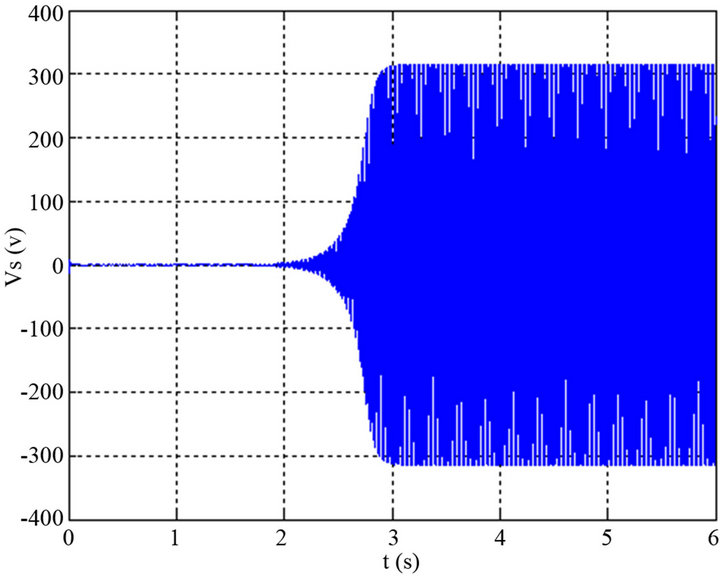
Figure 5. Evolution of the output voltage Vs versus time for (V = 9 m/s and C = 65 F).
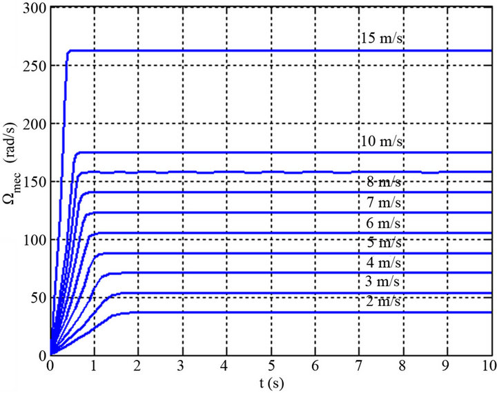
Figure 6. Evolution the angular velocity on the generator shaft to the speed of the wind.

Figure 7. Variation of stator RMS voltage versus time for different values of capacity and for R = 300 ohms and V = 9 m/s.

Figure 8. Variation of stator RMS voltage versus time for different resistance and for C = 65 F and V = 9 m/s.

Figure 9. Variation of stator effective voltage versus time for various wind speeds and for R = 300 ohm and C = 65 F.
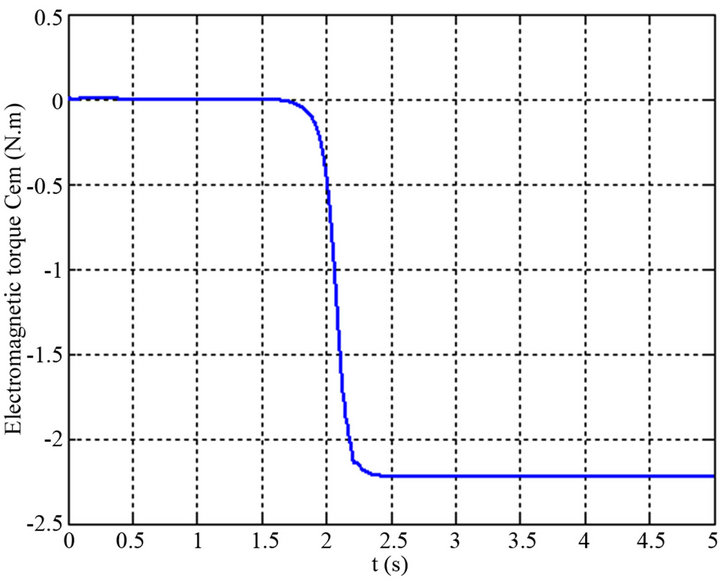
Figure 10. The electromagnetic torque of empty (no-load) SEIG for (V = 9 m/s, C = 65 F).
system without regulation when it submitted the changes in the wind speed, in the ability of excitation and in the load.
2.5.2. Start-Up on the Resistive Load
Figure 11 shows the voltage shape Vs of a stator phase in function of the capacity and for different values of the wind speed and the resistive load R = 100 Ω.
Figure 12 shows the evolution of the voltage Vs as a function of the capacity, but, in this case, for different load values. We observe that the voltage follows the same form for different values of the wind speed and the load, for this reason it is simple to find a control law of wind system.
Figure 13 shows the variation of the wind speed based on the capacitor for start-up of SEIG, in order to complete the study on the effect of different parameters

Figure 11. Variation in output voltage for each wind speed based on the ability of excitation to a load of 100 .
.

Figure 12. Variation of output voltage according to the excitation capacitor for different values of the load.

Figure 13. Variation of the minimum excitation capacitor depending on the speed of the wind.
(speed, capacity and load) on the system behavior especially on the output voltage. We also studied the influence of each parameters on other components. To determine an adaptive control of output voltage and will be our goal in the next section.
3. Adjusting the Output Voltage of the Wind System
3.1. System without Adjusting Voltage
Figure 14 shows the block diagram of a wind system which is based, in our case, on an induction machine and feeds a resistive load (RS) through a AC/DC converter.
3.2. The Simulation Result
For the values of the characteristic parameters the system of the Figure 14 (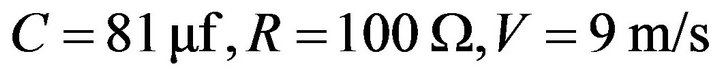 and filter settings:
 ), we obtained the results of simulation (Figure 15). We find that the output voltage is round 311 V which is our value searched.
3.3. Algorithm for Adjusting the Output Voltage of the Wind System
In a dynamic environment where the wind speed changes abruptly, the adaptation of the voltage across the load at a constant value (220 V) is necessary.
Based on previous results we deduce that the reactive power supplied by the capacitors boot generator is one of the parameters which is variable in relation to the value of the output voltage This relationship allows us to find an evolution law suitable with the voltage and wind speed (Equations (15) and (16)).
In this work we have taken a reference wind speed  with a fixed excitation capacitor
 . In less windy

Figure 14. Schematic diagram of a wind system with a rectifier connected to a resistive load.
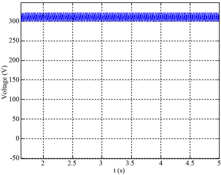
Figure 15. Evolution of the output voltage of the wind system with load.
areas we can consider that  for
for  and
and , the change in the excitation capacitor of the SEIG depending on the wind speed is an exponential function (Figure 16).
By interpolation polynomial we deduce:
 (15)
(15)
For , the change in the excitation capacitor of the SEIG depending on the wind speed is a hyperbolic function (Figure 17).
By interpolation polynomial we deduce:
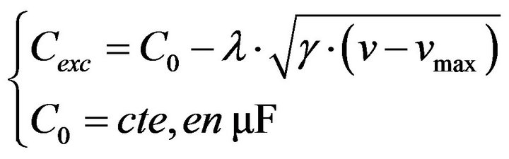 (16)
(16)
From the previous results (15) and (16), we deduced an algorithm to adjust the voltage reference value which

Figure 16. Evolution of the amended capacity for wind speed less than .
.
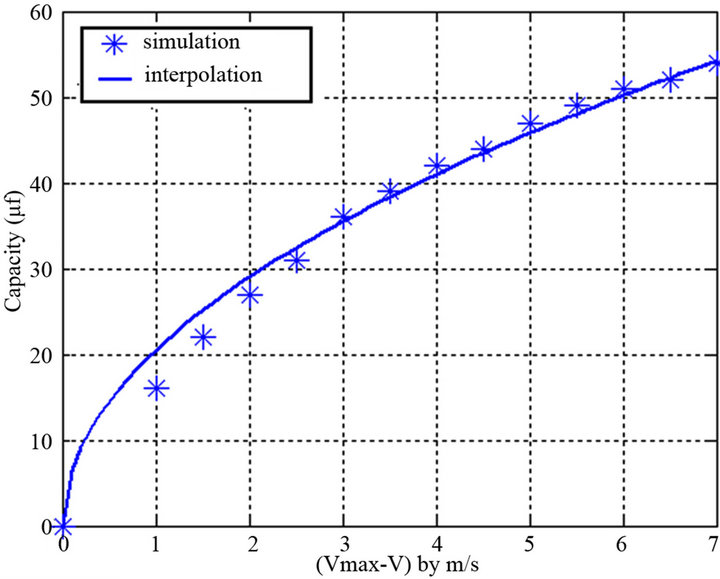
Figure 17. Evolution of the amended capacity for wind speeds greater than .
.
simulate the wind system in MATLAB/SIMULINK, in Figure 18.
3.4. Results of Simulation of Wind System with Adaptive Control
On the curves of Figure 19 we represented the typical
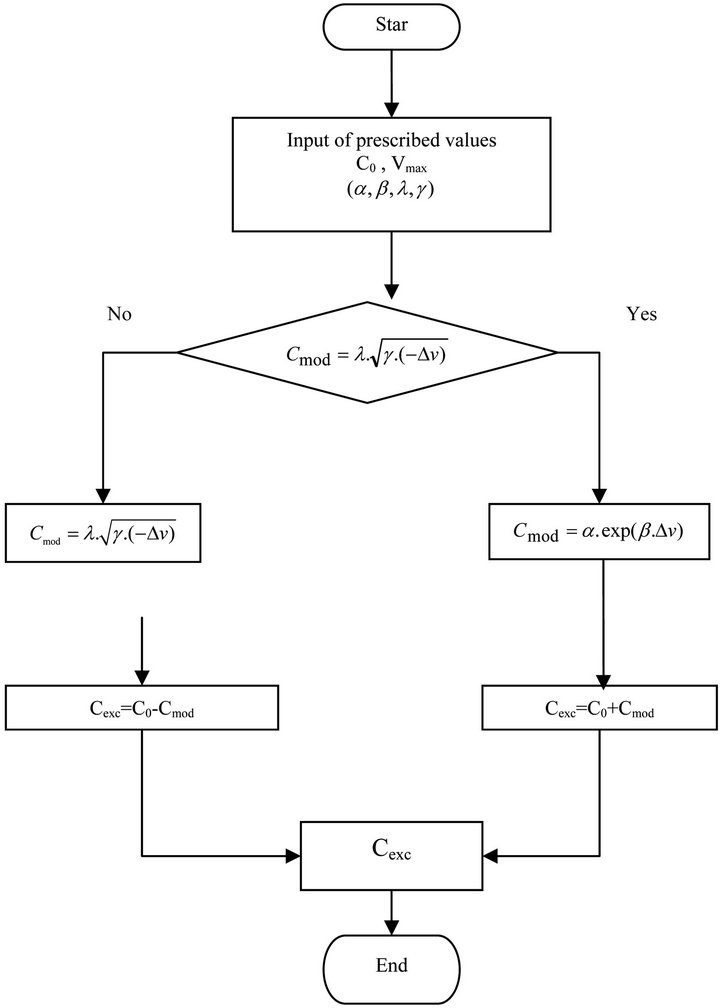
Figure 18. Algorithm for calculating the capacity of modified seed generator.
 (a)
(a)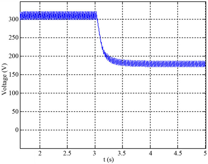 (b)
(b)
Figure 19. Evolution of the output voltage with a sharp decrease (a) Evolution of the output voltage with a sharp decrease in wind speed of 9 m/s to 8 m/s; (b) Evolution of the output voltage with a sharp decrease in wind speed of 9 m/s to 7 m/s.
simulation results in Matlab/Simulink, of the output voltage of the rectifier (voltage delivered by the SEIG).
The aim is to study the behavior of the system without regulation when he submitted a variation on the wind speed for 
 .
.
On the curves of Figure 20 we represented the same conditions of the Figure 19, the typical simulation results of the output voltage rectifier controlled by the adaptive control of the Figure 18.
The simulation results show that:
• The output voltage of the system of Figure 20 remains at a constant value whatever is the value of the wind speed in the turbine terminals.
• The adaptive control by reaction capabilities of exci-
 (a)
(a) (b)
(b)
Figure 20. Evolution of the output voltage with a sharp decrease in wind speed of 9 m/s to 8 m/s with adapting the reactive power excitation. (a) Evolution of the output voltage with a sharp decrease in wind speed of 9 m/s to 8 m/s; (b) Evolution of the output voltage with a sharp decrease in wind speed of 9 m/s to 7 m/s.
tation is effective and efficient; it allows the convergence of the system after a suitable time.
4. Conclusion
In this paper, we have presented the results of study of a system consisting of a wind turbine and an asynchronous generator connected to an AC/DC converter and a LC filter to supply a resistive load. Algorithm for adjusting reactive power excitation is proposed to maintain the voltage at a fixed value with an increase or decrease in the wind speed from a reference value. For the practical implementation of our control studied in this paper, we have opted to use a filters based on active dimmer or UPS (capacity varies), making these switches control as ways to track the value of the desired capacity. Thus, these results should be supplemented by an analysis of power losses in the changing speed moment.
REFERENCES
- Y. Zidani and M. Naciri, “A Steady State Analysis of the Self Excited Induction Generator Controlled by an Electronic Load Governor,” 4th IEEE on PEDS Power Electronics and Drive Systems, Bali, 22-25 October 2001, pp. 903-907.
- M. L. Elhafyani, S. Zouggar, Y. Zidani and M. Benkaddour, “Permanent and Transient Behavior of a Self-Excited Asynchronous Machine in Balanced Regime,” PREMME 2005, My Ismail University, FST, Errachidia, 15-16 September 2005.
- M. L. Elhafyani, S. Zouggar, Y. Zidani and M. Benkaddour, “Permanent and Dynamic Behaviours of Selfexcited Induction Generator in Balanced Mode,” M. J. Condensed Mater, Vol. 7, No. 1, 2006, pp. 49-53.
- A. Kishore, R. C. Prasad and B. M. Karan Birla, “Institute of Technology, India MATLAB SIMULINK Based DQ Modeling and Dynamic Characteristics of Three Phase Self Excited Induction Generator Progress in Electromagnetics Research Symposium,” Cambridge, 26-29 March 2006.
- M. Lopez, P. Dessante, D. Morales, J.-C. Vannier and D. Sadarnac, “Optimisation of a Small Non Controlled Wind Energy Conversion System for Stand-Alone Applications,” International Conference on Renewable Energies and Power Quality, Seville, 28-30 May 2007.
- Y. Zidani, S. Zouggar and M. Ghammouri, “Using an Active Filter for Voltage Regulation in a Self Excited Asynchronous Machine,” International Renewable Energy Symposium (CER 2007), E11, Oujda, 4-5 May 2007.
- M. L. Elhafyani, S. Zouggar, A. Aziz and M. Benkaddour, “Design and Modeling of a Wind System Controlled by a Voltage Regulator,” Renewable Energy Journal CER, CER’2007, Oujda, 4-5 May 2007, pp. 41-45.
- Y. Zidani and M. Naciri, “A Numerical Analytical Approach for the Optimal Capacitor Used for the Self Excited Induction Generator,” 32nd IEEE PESC Power Electronics Specialists Conference, Vancouver,17-22 June 2001, pp. 216-220.
- E. Mujadi, B. Gregory and D. Bord “Self Excited Induction Generators for Variable-Speed Wind Turbine Generation,” IEEE Industry Application Conference 34 IAS Annual Meeting, Arizona, 3-7 October 1999, pp. 343-352.
- K. Idjdarene, D. Rekioua, T. Rekioua and A. Tounzi, “Vector Control of Autonomous Induction Generator Taking Saturation Effect into Account,” Energy Conversion and Management Science, Vol. 49, No. 10, 2008, pp. 2609-2617.
NOTES
*Corresponding authors.