Smart Grid and Renewable Energy
Vol.2 No.2(2011), Article ID:4956,13 pages DOI:10.4236/sgre.2011.22011
Production of Freshwater and Energy from Earth’s Atmosphere
![]()
Consulting and Research Co., New York, USA.
Email: aBolonkin@juno.com
Renewal Electric Plant
Received January 24th, 2011; revised March 12th, 2011; accepted March 16th, 2011.
Keywords: Extraction Freshwater, Method of Getting Freshwater, Receiving Energy from Atmosphere, Powerful
ABSTRACT
The author offers a new, cheap method for the extraction of freshwater from the Earth’s atmosphere. The suggested method is fundamentally dictinct from all existing methods that extract freshwater from air. All other industrial methods extract water from a saline water source (in most cases from seawater). This new method may be used at any point in the Earth except the Polar Zones. It does not require long-distance freshwater transportation. If seawater is not utilized for increasing its productivity, this inexpensive new method is very environmentally-friendly. The author’s method has two working versions: 1) In the first variant warm (or hot) atmospheric air is lifted by the inflatable tube in a high altitude and atmospheric water vapor is condensed into freshwater; 2) in the second version, the warm air is pumped 20 - 30 meters under the sea-surface. In the first version, wind and solar heating of air are used for causing air flow. In version 2) wind and fans are used for causing air movment. The first method does not need energy, the second needs a small amount. Moreover, in variant 1) the freshwater has a high pressure (> 30 or more atm) and can be used for production of energy such as electricity and in that way the freshwater cost is lower. For increasing the productivity the seawater is injected into air and a solar air heater may be used. The solar air heater produces a huge amount of electricity as a very powerful electrical generation plant. The offered electricity installation is 100 - 200 times cheaper than any common electric plant of equivalent output.
1. Introduction
The suggested method requests the high tower. The early offered high towers [1-19] may be useful for design of given tower for getting the freshwater and energy from atmosphere.
A Freshwater [20-24] body contains low concentrations of dissolved salts and other total dissolved solids. It is an important renewable resource, necessary for the survival of most terrestrial organisms, and required by humans for drinking and agriculture, among many other uses.
Freshwater can be defined as water with less than 0.5 parts per thousand dissolved salts. Freshwater bodies include lakes, rivers, and some bodies of underground water. The ultimate source of fresh water is the precipitation of atmosphere in the form of rain and snow.
Access to unpolluted fresh water is a critical issue for the survival of many species, including humans, who must drink fresh water in order to survive. Only three percent of the water on earth is freshwater in nature, and about two-thirds of this is frozen in glaciers and polar ice caps. Most of the rest is underground and only 0.3 percent is surface water. Freshwater lakes contain seven-eighths of this fresh surface water. Swamps have most of the balance with only a small amount in rivers.
It is estimated that 15% of world-wide water use is for household purposes. These include drinking water, bathing, cooking, sanitation, and gardening. Basic household water requirements are at around 50 liters per person per day, excluding water for gardens. Many countries and regions do not have enough freshwater.
Desalination refers to any of several processes that remove the excess salt and other minerals from water in order to obtain fresh water suitable for animal consumption or irrigation, and if almost all of the salt is removed for human consumption, sometimes the process produces table salt as a by-product. Desalination of ocean water is common in the Middle East (because of water scarcity) and the Caribbean, and is growing fast in the USA, North Africa, Singapore, Spain, Australia and China.
Desalination of brackish water is done in the United States in order to meet treaty obligations for river water entering Mexico. Several Middle Eastern countries have energy reserves so great that they use desalinated water for agriculture. Saudi Arabia's desalination plants account for about 24% of total world capacity.
Current methods of extraction fresh water [21]. There are a lot of methods for distillation: Distillation, Evaporation/Condensation, Multiple-effect. Membrane processes, Electrodialysis reversal, Nanofiltration, Freezing, Solar humidification, Methane hydrate crystallisation, vacuum distillation, and so on. All request a lot of energy and produce high cost freshwater.
As of July 2004, the two leading methods were Reverse Osmosis (47.2% of installed capacity world-wide) and Multi Stage Flash (36.5%).
Reverse Osmosis. In the last decade, membrane processes have grown very fast, and Reverse Osmosis (R.O.) has taken nearly half the world’s installed capacity. Membrane processes use semi-permeable membranes to filter out dissolved material or fine solids. The systems are usually driven by high-pressure pumps, but the growth of more efficient energy-recovery devices has reduced the power consumption of these plants and made them much more viable; however, they remain energy intensive and, as energy costs rise, so will the cost of R.O. water.
The membranes used for reverse osmosis have a dense barrier layer in the polymer matrix where most separation occurs. In most cases the membrane is designed to allow only water to pass through this dense layer while preventing the passage of solutes (such as salt ions). This process requires that a high pressure be exerted on the high concentration side of the membrane, usually 2 - 17 bar (30 - 250 psi) for fresh and brackish water, and 40 - 70 bar (600 - 1000 psi) for seawater, which has around 24 bar (350 psi) natural osmotic pressure which must be overcome.
This process is best known for its use in desalination (removing the salt from sea water to get fresh water), but has also purified naturally occurring water for medical, industrial process and rinsing applications since the early 1970s.
Multi-stage flash distillation is a desalination process that distills sea water by flashing a portion of the water into steam in multiple stages. First, the seawater is heated in a container known as a brine heater. This is usually achieved by condensing steam on a bank of tubes carrying sea water through the brine heater. Thus heated, the water is passed to another container known as a “stage”, where the surrounding pressure is lower than that in the brine heater. It is the sudden introduction of this water into a lower pressure “stage” that causes it to boil so rapidly as to flash into steam. As a rule, only a small percentage of this water is converted into steam. Consequently, it is normally the case that the remaining water will be sent through a series of additional stages, each possessing a lower ambient pressure than the previous “stage”. As steam is generated, it is condensed on tubes of heat exchangers that run through each stage.
Cogeneration. There are circumstances in which it may be possible to use the same energy more than once. With cogeneration this occurs as energy drops from a high level of activity to an ambient level. Distillation processes, in particular, can be designed to take advantage of cogeneration. In the Middle East and North Africa, it has become fairly common for dual-purpose facilities to produce both electricity and water. The main advantage being that a combined facility can consume less fuel than would be needed by two separate facilities.
Economics. A number of factors determine the capital and operating costs for desalination: capacity and type of facility, location, feed water, labor, energy, financing and concentrate disposal. Desalination stills now control pressure, temperature and brine concentrations to optimize the water extraction efficiency. Nuclear powered desalination might be economical on a large scale, and there is a pilot plant in the former USSR. The world fresh water Resources and average annual water runoff are shown in Figures 1 and 2.
Critics point to the high costs of desalination technologies, especially for poor third world countries, the impracticability and cost of transporting or piping massive amounts of desalinated seawater throughout the interiors of large countries, and the “lethal byproduct of saline brine that is a major cause of marine pollution when dumped back into the oceans at high temperatures”. While noting that costs are falling, and generally positive about the technology for affluent areas that are proximate to oceans, one study argues that “Desalinated water may be a solution for some water-stress regions, but not for places that are poor, deep in the interior of a continent, or at high elevation”. Unfortunately, that includes some of the places with biggest water problems. Indeed, one needs to lift the water by 2000 m, or transport it over more than 1600 km to get transport costs equal to the desalination costs. Thus, desalinated water is only really expensive in places far from the sea, like New Delhi, or in high places, like Mexico City. Desalinated water is also expensive in places that are both somewhat far from the sea and somewhat high, such as Riyadh and Harare. In other places, the dominant cost is desalination, not transport. This leads to relatively low costs in places like BeijingBangkok, Zaragoza, Phoenix, and, of course, coastal cities
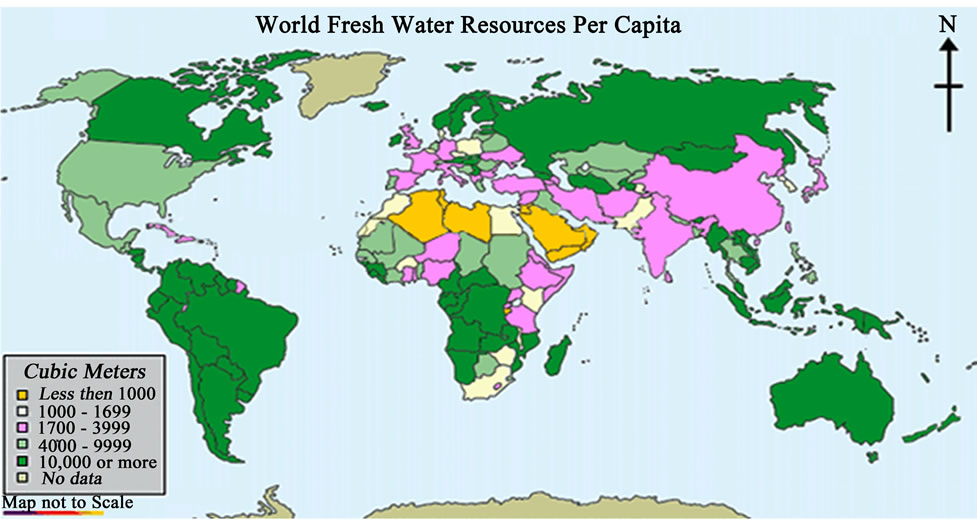
Figure 1. World fresh water resources.
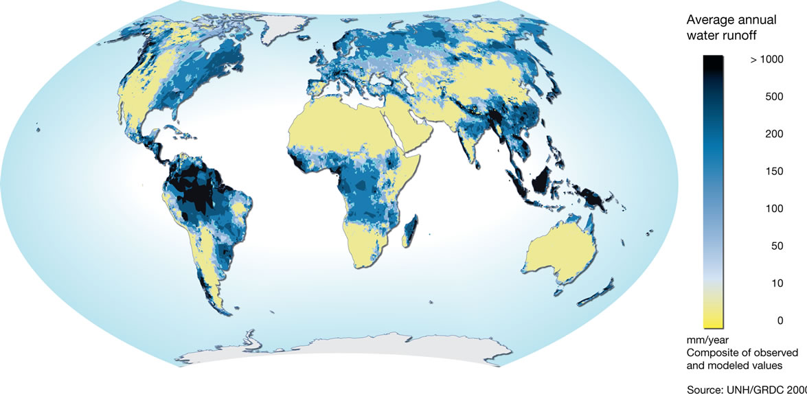
Figure 2. Average annual water runoff.
like Tripoli.
The desalination technology requests a lot of energy. The World energy possibilities are shown in Figure 3.
Environmental [22]. Regardless of the method used, there is always a highly concentrated waste product consisting of everything that was removed from the created “fresh water”. These concentrates are classified by the U.S. Environmental Protection Agency as industrial wastes. With coastal facilities, it may be possible to return it to the sea without harm if this concentrate does not exceed the normal ocean salinity gradients to which osmoregulators are accustomed. Reverse osmosis, for instance, may remove 50% or more of the water, doubling the salinity of ocean waste.
The hypersaline brine has the potential to harm ecosystems, especially marine environments in regions with low turbidity and high evaporation that already have elevated salinity. Examples of such locations are the Persian Gulf, the Red Sea and, in particular, coral lagoons of atolls and other tropical islands around the world. Because the brine is more dense than the surrounding sea water due to the higher solute concentration, discharge into water bodies means that the ecosystems on the bed of the water body are most at risk because the brine sinks and remains there long enough to damage the ecosystems. Careful re-introduction attempts to minimize this problem.
The benthic community cannot accommodate such an extreme change and many filter-feeding animals are destroyed when the water is returned to the ocean. This presents an increasing problem further inland, where one needs to avoid ruining existing fresh water supplies such as ponds, rivers and aquifers. As such, proper disposal of “concentrate” needs to be investigated during the design phase.
Experimental techniques and other developments. In the past many novel desalination techniques have been researched with varying degrees of success. Some are still on the drawing board now while others have attracted re-
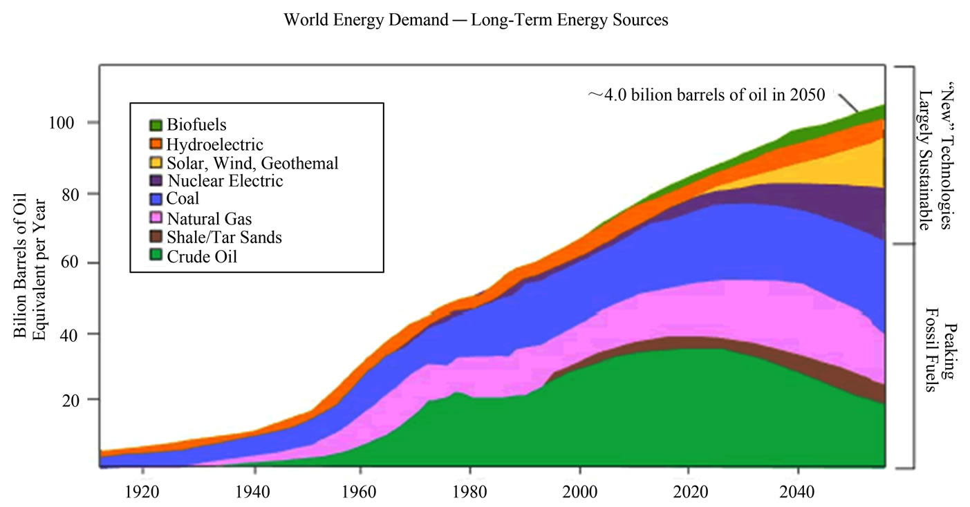
Source:Lynn Orr, Changing the World’s Energy Systems, Stanford University Global & Energy Project (after John EwardsAmerican Association of Petroleum Geologists); SRI Consulting
Figure 3. Current and future demand of World Energy.
search funding. For example, to offset the energetic requirements of desalination, the U.S. Government is working to develop practical solar [23] desalination.
Other approaches involve the use of geothermal energy. An example would be the work being done by SDSU CITI International Consortium for Advanced Technologies and Security. From an environmental and economic point of view, in most locations geothermal desalination can be preferable to using fossil ground-water or surface water for human needs, as in many regions the available surface and groundwater resources already have long been under severe stress.
About 577 000 km3 water vaporizes from Earth’s surface in one year (505 000 km3 of them from oceans). One person consumes from 10 - 50 liters per day (the last number for industrial countries and includes the watering of house gardens). Plants require large quantities of water. For example, one hectare of wheat requires 2000 kL (kL is kiloliter = 1 ton), the cabbage - 8000 kL, a hectare of forest requires 12 000 - 15 000 kL per summer.
The author offers a new cheap method for extraction of freshwater from atmosphere and incidentally the extraction of energy. This method may be used at any point of Earth except the polar regions. It does not require long distance transportation of water or to import large amounts of fuel or supplies. If you not use seawater injection for increasing its productivity, this method is very friendly to the environment [20-23]. Related works and information about this topic the reader may find in [1-24].
2. Method
2.1. Description of Innovations
2.1.1. High Height Tube Extractor and Electric Plant
The offered extractor is shown in Figure 4. The main part is an inexpensive inflatable high altitude tube 1 (up to 3 - 5 km tall) supported by bracing wires 14. This Tube is designed from inflatable toroids (rings) 13. They preserve the overall tube form (a stacked pile of rings). Tube has freshwater collector 2 and freshwater pipeline 3 inside. The tube can have a film solar heater 8 (optional) located on ground. That is constructed of a bubble of transparent film over the ground (a black surface provided to absorb it). The entering air flows between film and ground and is heated by solar radiation. That strongly increases the speed of airflow (see computation). If we additionally inject saline water 7 into the airflow, we additionally increase the water productivity (see computation section). The installation can have a propeller 15 for increased airflow in windless weather. The top end of tube has air turbine and electric generator 19. The top end can also has an wind turbine 20 (optional). The top end has also the observation desk 16 and elevator 18. The tube enter and exit 10 (Figure 4) have wind leafs (2, 3 in Figure 5). The other parts are noted under Figures 4 and 5.
The installation works the following way. The wind leafs (slats to control air flow) (2, 3 in Figure 5) automatically are opened so to use the wind dynamic pressure
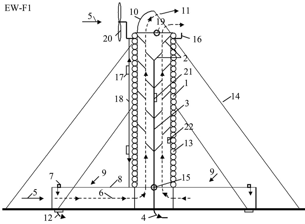
Figure 4. Inflatable extractor freshwater from atmosphere and electric plant (side view). Notation: 1, vertical tube; 2, freshwater collector; 3, freshwater pipe line; 4, exit of freshwater; 5, wind; 6, air flow; 7, injector of sea (saline) water (optional); 8 , transparent film and solar heater of air (optional); 9, solar radiation (optional); 10, air exit; 11, air flow; 12, collector of seawater (optional); 13, inflatable toroid; 14, support cable (bracing wire); 15, ventilator (wind turbine) (optional); 16, observation desk for tourists and communication installation (optional); 17, passenger cabin; 18, elevator; 19, top propeller-electric generator; 20, wind electric generator; 21 and 22, mobile cabins.

Figure 5. Inflatable extractor freshwater from atmosphere (top view). Notation: 1, vertical inflatable tube; 2, solar heater (optional); 3, wind leafs of solar heat; 4, wind leafs of air exit; 5, wind at ground; 6, wind at altitude; 7, solar radiation; 8, exit tube air flow; 9, tube support cable.
(and to draw off for top end of tube). The air enters into the solar heater 8 (or in entrance of tube when the solar heater is absent), is warmed and goes to the vertical uplift tube. At high altitude the air expands, cools and air steam (water vapor) condenses in the water collector. The pipeline delivers the freshwater under high pressure (because the altitude is high) and it may flow to an uphill, waterneedy region. The high pressure of water may be used alternatively for production of energy (electricity). Moreover, we can install an air turbine and electric generator at the top of tube and get electricity when we do not need a large amount of freshwater. In this case the solar energy of the solar heater is transferred into electric energy (see computation).
2.1.2. Sea Air-Water Extractor
The sea air-water extractor is shown in Figure 6. This has the air/wind dynamic entrance and exit that are the same as the previous version. New in this version is a sea heat exchanger. That is located at a depth 20 - 30 meters where temperature is 5˚C - 10˚C. (in the open ocean; in a closed sea such as, for example, the Mediterranean, it is typically almost 13˚C) The sea heat exchanger is made from steel tubes, which can withstand 2 - 3 atm outer pressure. For increased productivity the installation has a propeller (fan, air pump) that moves the air through the tube and seawater injector. That can also have solar air heater same as the previous variant.
Possible forms of the offered towers are shown in Figures 7 and 8.
2.2. Computations and Estimations
A reader can get the equations in below from well-known physical laws. Therefore the author does not give detailed derivations or explanations.
2.2.1. Amount of Water in Atmosphere
The amount of water in atmosphere depends upon ambient temperature and humidity. For relative humidity 100% the maximum partial pressure of water vapor is shown in Table 1.
The amount of water in 1 m3 of air may be computed by equation
 , (1)
, (1)
where mW is mass of water, kg in 1 m3 of air; p(t) is vapor (steam) pressure from Table 1, relative h = 0 ¸ 1 is relative humidity. The computation of Equation (1) is presented in Figure 9. Typical relative humidity of atmosphere air is 0.5 - 1. Standard atmosphere is in Table 2.
2.2.2. The Wind Dynamic Pressure
The wind dynamic pressure is computed by equation
 , (2)
, (2)
where pd is wind dynamic pressure, N/m2; r is air density, for altitude H = 0 the r = 1.225 kg/m3; V is wind speed, m/s.
The same Equation (2) is used for decreasing of air pressure in the tube exit. The computation is presented in Figure 10.
2.2.3. Additional Decreasing Air Pressure from Warm Air
When entering air is warmer than atmospheric air (for example is heated by solar heater, Figure 4) the pressure of tube air column is less than atmosphere pressure and air is sucked skyward by vertical tube. This additional air pressure (or rarefaction) may be estimated by equation
 , (3)
, (3)
Figure 6. Sea extractor freshwater from atmosphere. Notations: 1, wind; 2, air entrance; 3, solar air heater; 4, injector of sea water; 5, collector of superfluous sea water; 6, air ventilator; 7, air tube; 8, radiator (heat exchanger); 9, exit air tube; 10, exit air flow; 11, air flow; 12, freshwater line; 13, sea; 14, ground.

Figure 7. Possible forms of the offered towers.

Figure 8. Right: Possible form of the offered tower.

Table 1. Maximum partial pressure of water vapor in atmosphere via air temperature.
where pT is additional air pressure (rarefaction), N/m2; p0 is atmospheric pressure on Earth’s surface, N/m2; m = 28.96 is molar weight of air ; g = 9.81 m/s2 is Earth gravity; H is altitude, m; R = 8314 is gas constant, t is average air temperature, K; dt is increasing of air temperature, K.
The computations are presented in Figure 11.
2.2.4. Altitude Wind Speed
Wind speed, V, increases with altitude, H, as follows
 (4)
(4)
where a = 0.1 - 0.25 exponent coefficient depends from surface roughness. When the surface is water, a = 0.1; when surface is shrubs and woodlands a = 0.25. The sub “0” means the data at Earth surface. The standard values for wind computation are Vo = 6 m/s, Ho = 10 m/s. The computations of this equation are presented in Figure 12.

Figure 9. Amount of water in 1 m3 of air versus air temperature and relative humidity (rh) t1 = 0 ˚C.
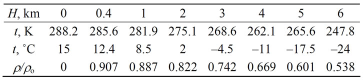
Table 2. Standard atmosphere ro = 1.225 kg/m3.

Figure 10. Wind dynamic pressure versus wind speed and air density.
2.2.5. The Air Friction of Tube Walls
The air friction of tube walls is computed by equation
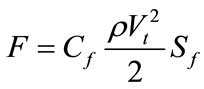 (5)
(5)
where F is friction force, N; Cf is friction coefficient, Cf = 0.001 ¸ 0.002 for laminar air flow and Cf = 0.005 ¸ 0.01 for turbulent air flow; r is average air density, kg/m3; Vt is air speed into tube, m/s; Sf is a friction surface, m2.
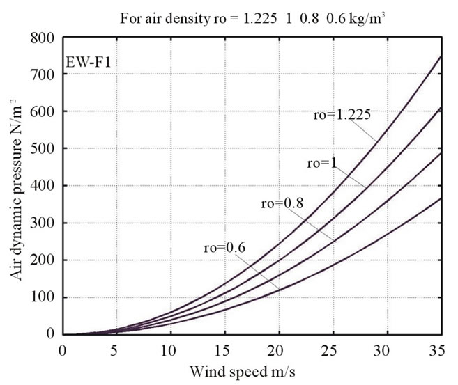
Figure 11. Additional air pressure (rarefaction) into vertical tube versus altitude and additional air warming (dt) by solar heater.
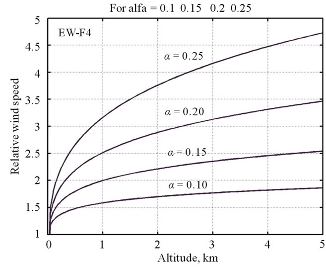
Figure 12. Relative wind speed versus altitude for Vo = 6 m/s, Ho = 10 m/s.
2.2.6. Air Speed into Tube
From balance of pressure we can get the equation for air speed into tube
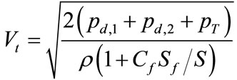 (6)
(6)
where pd,1, pd,2 are wind dynamic pressure in entrance and exit of tube respectively, N/m2; pT is warm air pres sure, N/m2; r is average air density into tube, kg/m3; S is cross-section area of tube, m2.
The results of computation are shown in Figure 13.
2.2.7. Air Propeller at Tube Entrance (Expense of Energy for Air Pumping)
The sea air-water extractor needs the air propeller (pump) in entrance of tube for cases when the wind is absent or for the increasing the fresh water production. This propeller may be used when no wind and sun.
The power N (and consumption of energy) of this propeller can be computed by equation
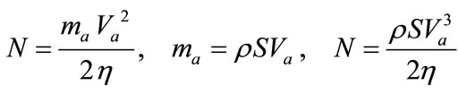 (7)
(7)
where ma is mass of pumped air, kg/s; Va is additional speed of pumped air, m/s; h » 0.8 ¸ 0.9 is coefficient of propeller efficiency. The computations are presented in Figure 14.
2.2.8. Getting of Energy from High Altitude Freshwater
The energy may be received from freshwater condensed into vertical tube at high altitude. The power of high altitude freshwater Nh can be computed by equation
 (8)
(8)
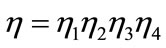
where h = 0.9 ¸ 0.94 is summary efficiency of water turbine and electric generator; Mw is mass of freshwater, kg; H is altitude of condensation, m.
As an interesting example we compute the energy from high altitude freshwater. Let us take the following initial typical data for air (non sea) extractor: Air temperature is t = 35˚C, humidity is h = 0.7, the entrance area of vertical tube S = 4 ´ 104 m2 (radius tube is 113 m), airspeed in tube is V = 4 m/s, standard air density r = 1.225 kg/m3.
Then the air consumption is C = rSV = 160 000 m3/s (about 200 tons/s). One m3 of air contains mw = 0.0216 kg/m3 of freshwater (see Equation (1)) suitable for condensation. The flow of freshwater (freshwater productivity of installation) is Mw = mwC = 3460 kg/s, Liter/s). They produce an energy of N = hMwH = 31´103 kW.
The reader might object to this as an example of a per-
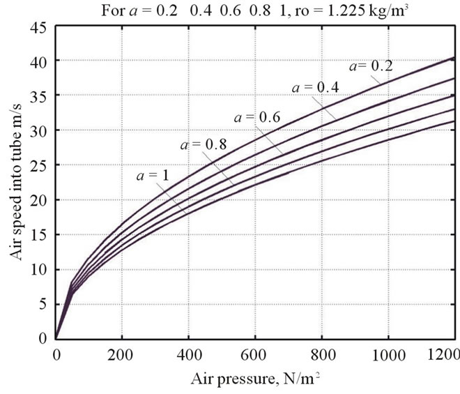
Figure 13. Air speed into tube versus sum of air pressurefor different values a = Cf Sf /S.
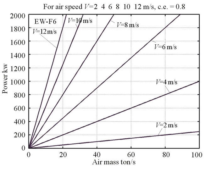
Figure 14. The power needed for air pumping versus air pumped mass and additional air flow speed. Coefficient pump efficiency h = 0.8.
petual motion engine! When wind and Sun are absent (night time), you spend 2000 kW power for moving (blowing) 200 tons/s of air for speed 4 m/s (Figure 9) and get 31 000 kW energy (in 15 times more!) plus freshwater. It is not surprising however. The air expands at high altitude and produces net energy. The same situation is in rain, mountain rivers and glaciers. The sun has already “paid” for this energy gain—the potential energy is already there invisibly in form of heat and vapor.
2.2.9. Obtaining Energy from Solar Heater
When the vertical tube extractor has a solar air heater at lower end and air turbine (plus electric generator) at top of tube, we can get additional energy. The solar radiation heats the air. The warm air makes a less pressure into tube; the airflow into tube has more (high) speed and air turbine at a top tube end produces the energy. This energy (power) may be estimated by equation
 (9)
(9)
where N is power, W; h is efficiency coefficient, q = 1400 W/m2 is solar power at Earth’s orbit in 1 m2, W/m2; Sh is area of solar heater, m2.
The coefficient of efficiency is product of the efficiency coefficients of the series of devices which take part in energy transferring and change:
 (10)
(10)
where h1 = 0.1 ¸ 0.8 allows for the loss in atmosphere (top value for cloudless time); h2 = 0 ¸ 1 account the heater location and its position to solar ray direction; h3 = 0.8 ¸ 0.95 allows for air friction loss into tube; h3 = 0.9 ¸ 0.95 is common air turbine + electric generator efficiency coefficient. As the result the solar heater has h = 0 ¸ 0.75. If solar heater has area 1 ´ 1 km, located near equator and on a sunny day, the maximum energy will be about N = 0.7 ´ 1400 ´ 106 » 1 GW energy. The daily energy (include the night time) will be on average three-four times less approximately 250 ¸ 330 MW.
If we make transparent the outer layer of tube and black the internal layer, the tube may be used as a solar heater. The tube having diameter equals 200 m and height 4 km has useful (for heating) surface area of 0.8 km2.
The tube exit air speed V may be estimated by equations
 (11)
(11)
where r is air density at altitude, kg/m3; S is cross-section of tube exit, m2.
2.2.10. Seawater Injection into Tube
Correct injection of seawater into airflow increases the humidity of the air (up to the maximum possible), but on the other side, vaporization of water requests a lot of energy and decreases the temperature of air flow. This decreasing of air temperature we can estimate from equation of heat balance
 , (12)
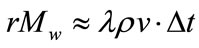
where r = 2260 kJ/kg is energy of water vaporization; Mw is expensed mass of water, kg/s; l = 1 kJ/kg·˚C is heat capacity of air; v is air flow, m3/s; Dt is increasing of air temperature, ˚C.
From Equation (12) we find that vaporization 1 g water decreases the temperature of 1 m3 air in 1.84˚C. That decreasing is bad for atmospheric extractor with vertical tube because the decreases the speed of airflow (and total amount of freshwater) and that is good for sea extractor because decreases sea heat exchanger and increases the fresh water production. Last means: the sea exchanger must works all time in maximum humidity of air.
2.2.11. Solar Heater for Vertical Extractor
The size of solar heater for vertical extractor - electric generator may be estimated from heat balance:
 (13)
(13)
where Q is request heat, J; l = 1 kJ/kg·˚C is heat capacity of air; Ma is air mass flow, kg/s; Vt is air speed into tube entrance, m/s; S is cross-section area of tube entrance, Sh is requested the heater area, m2; r = 1.225 kg/m3 if air density; q » 6000 ¸ 1000 W/m2 is solar radiation on Earth’s surface.
Equation (13) gives: for heating of 1 m3/s of airflow in 1˚C we need a minimum about 1.5 ¸ 2 m2 of the solar heater.
In daytime the Sun stockpiles the ground or water (reservoir) with heat. We can use this stockpile of heat for increasing the humidity and power potential of the incoming air in the nighttime.
2.2.12. Heat Exchanger for Sea Extractor
The transferring of heat in sea exchanger may be computed by equation
 , (13)
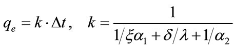
where qe is heat transmission, W/m2; k is coefficient of heat transmission, W/m2·˚C; a1 » 100 is coefficient of heat transmission from air to tube wall, W/m2·˚C; a2 » 5000 W/m2·˚C is coefficient of heat transmission from water to tube wall, W/m2·˚C; d is thickness of tube wall, m; l » 50 W/m2·˚C is coefficient of heat transmission from through steel wall; x = 1 ¸ 20 is coefficient of ribbing the gilled-tube radiator.
For x = 10, d = 0.01 m the coefficient k = 700 W/m2 ˚C.
2.2.13. Cost of Freshwater Extractor
The cost of produced freshwater may be estimated by the equation
 , (14)
where C is cost of installation; l is live time of installation, years; Me is annual maintenance; c is cost of energy unit;
Ey annual expense of energy (net production of energy is indicated by a minus sign); Mwy is annual amount of received freshwater.
The retail cost of electricity for individual customers is $0.18 per kWh at New York in 2007. Cost of other energy from other fuel is in [8, p.368.] Average cost of water from river is $0.49 - 1.09/kL in the USA.
2.2.14. Energy is Requested by the Different Methods
Below in Table 3 is some data about expense of energy for different methods.
As you see the offered sea extractor decreases the energy expense in 1000 times. The high tube extractor produce freshwater and give a good energy.
2.2.15. Using the High Altitude Tube of Extractor for Tourism, Communication and Wind Energy
The high altitude tube tower can give good profit from tourism. As it shown in [8, p. 93] for 4800 tourists in day and ticket cost $9 the profit will be about $15 million/ year.
The profit may be from communication (TV, cell telephone, military radars, etc). The very good profit will be from high altitude wind electric station [4] (for wind speed V = 13 m/s at H = 4 km, wind rotor R = 100 m the power will be about 20 MW. In reality the wind speed at this altitude is more strong (up 35 m/s), stable, and rotor may to have radius up 150 m. That means the wind power may reach up to 30 - 50 times more power.
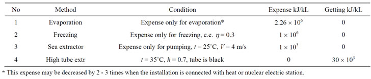
Table 3. Estimation of energy expenses for different methods of freshwater extraction.
3. Projects
3.1. High Tube Freshwater and Energy Extractor
Let us make some estimations of the high altitude tube freshwater extractor. Our data is far from optimum. Our aim is to demonstrate the methods of estimation and some possibility offered idea.
Take the radius of inflatable tube R = 115 m (S = 4 ´ 104 m2), height of tube H = 3 km, air temperature on Earth’s surface t = 25˚C, air relative humidity h = 0.7, wind speed V = 6 m/s. From equations and graphs above we get:
1)Amount of freshwater into 1 m3 of air is mw 0.0052 kg/m3 = 5.2 g/m3 [Equation (1)].
2)The average wind speed at altitude H = 3 km for a = 0.15 is V = 14 m/s [Equation (2)].
3)The wind dynamic pressure at H = 0 is p1 = 22 N/m2 and the air wind rarefaction at H = 3 km is p2 = 89 N/m2 [Equation (3)].
4)For average coefficient of air friction Cf = 0.005 and average air density r = 1.1 kg/m3 the air speed into tube is Vt = 12.6 m/s [Equation (3)].
5)The volume and mass of air flow are v = SV = 5 ´ 105 m3/s, Ma = rv = 612 tons/s.
6)The freshwater flow is Mw = vmw = 2600 L/s = 224640 kL/day = 7,862,4000 kL/year (1 kL = 1 ton).
Energy estimation:
1) Power from freshwater (H = 2500 m) is 60 MW.
2) Power from wind turbine on tube (one at top, R = 100 m, A = pR2, h = 0.5, V = 12.6 m/s) is N = 0.5hrAV3 = 14.3 MW.
3) Power from black tube (heating from Sun radiation, q = 500 W/m2) is 345 MW.
4) Power from solar heater on Earth’s surface (Sh = 1 ´ 1 km, q = 500 W/m2) is 500 MW. If solar heater has area Sh = 2 ´ 2 km the power will be 2000 MW. That is power of powerful electric station.
5) If night time and no wind, we can turn on the lower ventilator. For Va = 4 m/s the request ventilator power is 1.57 MW [Equation (8)]. But the getting energy from high altitude freshwater is 19 MW.
Cost of high tube extractor-generator. The cost of thin film (main construction material of inflatable tower and solar heater) is about $1/m2 US. The full area of tower (H = 3 km) is 2.2 km2, the area of Solar Heater (2 ´ 2 km) is 4 km2. The total cost of film is about $6.2 million (mln). Add the cost of 3 ventilator-electric generators - $3 mln. The total cost of offered installation (include building) may be about $20 mln. That is for the freshwater extractor of productivity 224640 kL/day and a powerful electric station with maximal power more than 2000 MW.
Each 1 MW of a nuclear electric station costs about $1 mln. The offered installation (electric plant same power) is cheaper a same nuclear electric station by 100 times. One is safe, friendly to environment, and produce free energy and freshwater. The nuclear station requires nuclear fuel and produces energy, which costs as in the conventional heat electric station.
Reminder, our estimation (data) is not optimal.
3.2. Sea Freshwater Extractor
Let us take the following initial data for estimation: air temperature is t = 30˚C, we have 4 tubes, each has radius R = 5 m, speed of pumped air V = 4 m/s, relative h = 1 (after injection of sea water), mw = 0.023 kg/m3 .
Then:
1) entrance cross-section area is S = 4 ´ p ´ R2 = 314 m2
2) second volume of air flow into tubes is v = SV = 1256 m3/s
3) flow of air mass is Ma = rv = 1540 kg/s, produced freshwater is Mw = vmw = 35.4 L/s = 3060 kL/day.
4) need (ventilator) power (h = 0.82) N = MaV2/2h = 15 kW
5) amount of the receding heat (from t2 = 30˚C to t1 = 10˚C) is Q = CpMa(t2 – t1) = 31 ´ 106 J/s
6) needed tube area of sea radiator for k = 700 W/m2˚C is Sr = Q/k = 4.4 ´ 104 m2.
If we use standard steel tubes d = 1.2 m, the radiator requests 58 tubes length 200 m.
4. Result, Discussion and Conclusions
Author began this research as investigation of new method for receiving cheap freshwater from atmosphere. In processing research he discovered that method allows producing huge amount energy, in particular, by transferring the solar energy into electricity with high efficiency (up 80%). If solar cell panels are very expensive and efficiency of about 15%, plastic thin film (as in shopping bags) is very cheap. They are thrown out hundreds of tons every day and harm the environment. The theory of inflatable space towers [1-5] allows to build very cheap high towers, which can be used also for tourism, communication, radio-location, producing wind electricity, space research [8].
The other methods and ideas are described in [1-24].
Reader finds some of author’s articles in http: //Bolonkin.narod.ru/p65.htm, http://www.scribd.com, http: //www.archive.org and http://arxiv.org, search “Bolonkin,” in books “Non-Rocket Space Launch and Flight,” Elsevier, 2006, 488pgs, http://www.archive.org/details/ Non-rocketSpaceLauncAndFlight and http://www.scribd. com/doc/24056182; “New concepts, Ideas and Innovation in Aerospace, Technology and Human Science,” NOVA, 2007, 502 pgs., http://www.scribd.com/doc /24057071; “Macro-Projects: Environment and Technology,” NOVA, 2008, 536 pgs., http://www.scribd.com/ doc/24057930; “New Technologies and Revolutionary Projects”, Scribd, 2009, 324 pgs, http://www.scribd.com/ doc/32744477.
5. Acknowledgements
The author wishes to acknowledge Joseph Friedlander (Shave Shomron, Israel) for correcting the author’s English and useful advice and suggestions.
REFERENCES
- A. A. Bolonkin, “Optimal Inflatable Space Towers of High Height,” COSPAR-02 C1.1-0035-02, Proceedings of the 34th Scientific Assembly of the Committee on Space Research, The World Space Congress, Houston, 10-19 October 2002, See also Ch. 3 in http://www.archive.org/details/Non-rocketSpaceLaunchAndFlight
- A. A. Bolonkin, “Optimal Inflatable Space Towers with 3 - 100 km Height”, Journal of the British Interplanetary Society, Vol. 56, No. 3/4, 2003, pp. 87-97. See also Ch.3 in http://www.archive.org/details/Non-rocketSpaceLaunchAndFlight
- A. A. Bolonkin, “Kinetic Space Towers and Launchers,” Journal of the British Interplanetary Society, Vol. 57, No. 1/2, pp. 33-39, 2004. See also Ch.4 in http://www.archive.org/details/Non-rocketSpaceLaunchAndFlight
- A. A. Bolonkin, “Utilization of Wind Energy at High Altitude,” AIAA-2004-5705, AIAA-2004-5756, Proceedings of the International Energy Conversion Engineering Conference at Providence, Rhode Island, 16-19 August 2004. http://arxiv.org/ftp/physics/papers/0701/0701114.pdf
- A. A. Bolonkin, “Optimal Solid Space Tower,” AIAA- 2006-7717, ATIO Conference, Wichita, 25-27 September 2006. http://arxiv.org/ftp/physics/papers/0701/0701093.pdf .
- A. Bolonkin and R. Cathcart, “A Low-Cost Natural Gas/Freshwater Aerial Pipeline,” 2006. http://arxiv.org/ftp/physics/papers/0701/0701061.pdf
- A. A. Bolonkin, “Cheap Textile Dam Protection of Seaport Cities against Hurricane Storm Surge Waves, Tsunamis, and Other Weather-Related Floods,” 2006. http://arxiv.org/ftp/physics/papers/0701/0701059.pdf
- A. A. Bolonkin, “Non-Rocket Space Launch and Flight,” Elsevier, Oxford, 2006. http://www.archive.org/details/Non-rocketSpaceLaunchAndFlight, http://www.scribd.com/doc/24056182
- A. Bolonkin and R. Cathcart, “The Java-Sumatra Aerial Mega-Tramway,” 2006. http://arxiv.org/ftp/physics/papers/0701/0701099.pdf
- A. Bolonkin and R. Cathcart, “Inflatable Evergreen Polar Zone Dome (EPZD) Settlements,” 2006. http://arxiv.org/ftp/physics/papers/0701/0701098.pdf
- A. A. Bolonkin and R. B. Cathcart, “A Cable Space Transportation System at the Earth’s Poles to Support Exploitation of the Moon,” Journal of the British Interplanetary Society, Vol. 59, No. 10, 2006, pp. 375-380. See also Ch.7 in http://www.scribd.com/doc/24057071.
- A. A. Bolonkin, “Non-rocket Space Launch and Flight,” book published in 2006, web in 2009. http://www.archive.org/details/Non-rocketSpaceLaunchAndFlight
- A. Bolonkin, “Control of Regional and Global Weather,” 2006. http://arxiv.org/ftp/physics/papers/0701/0701097.pdf
- A. Bolonkin and R. Cathcart, “Antarctica: A Southern Hemisphere Windpower Station?” 2006. http://arxiv.org/ftp/physics/papers/0701/0701055.pdf
- A. A. Bolonkin and R. B. Cathcart, “Inflatable ‘Evergreen’ Dome Settlements for Earth’s Polar Regions,” Clean Technologies and Environmental Policy 2006, doi 10.1007/s10098-006-0073-4. See also Part b Ch.4 in http://www.scribd.com/doc/24057930 http://www.archive.org/details/Macro-projectsEnvironmentsAndTechnologies
- R. Cathcart and A. Bolonkin, “The Golden Gate Textile Barrier: Preserving California Bay of San Francisco from a Rising North Pacific Ocean,” 2006. http://arxiv.org/ftp/physics/papers/0702/0702030.pdf
- R. Cathcart and A. Bolonkin, “Ocean Terracing,” 2006. http://arxiv.org/ftp/physics/papers/0701/0701100.pdf
- A. A. Bolonkin, Extraction of Freshwater and Energy from Atmosphere, 2006. http://arxiv.org/ftp/arxiv/papers/0704/0704.2571.pdf
- A. A. Bolonkin, R. Cathcart, “Macro-Projects: Technology and Environment,” 2008, NOVA, p. 536. http://narod.ru/disk/13292420000/Book_Macro_Projects_for_Internet%209%2018%2009.doc.html
- V. Badescu, R. Cathcart and R. Schuiling “Macro-Engineering—A challenge for the Future,” Collection of articles, Springer, London, 2006. (Collection contains Bolonkin’s articles: Space Towers; Cable Anti-Gravitator, Electrostatic Levitation and Artificial Gravity).
- P. Gleick, et al. (edited by S. H. Schneider) “Encyclopedia of Climate and Weather,” Oxford University Press, Oxford, 1996.
- Encyclopedia of Desalination and water and Water. http://www.desware.net
- “Encyclopedia of Earth—Surface Water Management,” http://www.eoearth.org/article/Surface_water_management
- “The MEH-Method (in German): Solar Desalination Using the MEH Method,” Diss. Technical University of Munich.
- Wikipedia, “Some Background Material in this Article is Gathered from Wikipedia under the Creative Commons License,” http://wikipedia.org