Energy and Power Engineering
Vol.5 No.3(2013), Article ID:31124,13 pages DOI:10.4236/epe.2013.53021
Theoretical Considerations about the Steady State Combustion of Wood Char in a Bubbling Fluidized Bed Reactor
Transport Phenomena Research Center, Department of Mechanical Engineering, Faculty of Engineering, University of Porto, Porto, Portugal
Email: ctp@fe.up.pt
Copyright © 2013 Carlos Pinho. This is an open access article distributed under the Creative Commons Attribution License, which permits unrestricted use, distribution, and reproduction in any medium, provided the original work is properly cited.
Received February 5, 2013; revised March 8, 2013; accepted March 22, 2013
Keywords: Biomass; Wood Char; Fluidized Bed
ABSTRACT
A theoretical study on the performance of steady state bubbling fluidized bed burners is presented using a simple mathematical model. The proposed model has pedagogical and practical advantages due to its simplicity. The calculations, whose results are plotted in several graphics, were based on data obtained in laboratory scale experiments. The experiments were carried out with wood chars and the model allows a proper evaluation of physical and chemical phenomena taking place inside the reactor, as well as a fast approach to the pre-design phase, before going towards more complex and time consuming numerical modeling. In the first part of the paper the steady state modeling is compared with the combustion of successive batches of char particles. Afterwards, the performance of a 1 m diameter bed operating from 700˚C to 800˚C is shown.
1. Introduction
The urgent need to use energy sources that could guarantee a reduction or the control of CO2 emissions has led many researchers to look for the renewable sources of energy, like biomass [1]. Wood is the oldest and the most relevant solar energy conveyor known and used by mankind [2-7]. Presently more than 15% of the primary energy consumed by mankind comes from the combustion of wood or ligneous residues [8], but the efficiency of combustion under these circumstances is low. The interest on this energy resource is raising and European Union targets as far as bioenergy is concerned are rather ambitious [9].
The use of biomass as an energy source in a country like Portugal, through the combustion of wood, can be considered under two ways, fast growing plant species exclusively dedicated to combustion leading to an exploitation rate of about 80 t/ha/year, or the use of the forest for other ends and using the corresponding ligneous forest cleaning waste of about 2 to 3 t/ha/year. These numbers are typical values for the Atlantic coast of the Iberian Peninsula [10-13]. In the use of forest cleaning residues it is necessary to avoid soil depletion of minerals and nutrients [14]. The forest cleaning process can then be considered, under very limited restrictions, a source of biofuel easing the economic costs of the cleaning operation [15]. In either of these situations the main attracttiveness is on the achievement of a closed carbon cycle [16-19].
In developing countries biomass is frequently the most important source of primary energy corresponding to 35 % of their energy needs [8,9,15]. In the developed countries the increase of the efficiency of biomass utilization is one important target. In the USA the efficiency of a power plant stays around 20% - 25% based on the higher calorific value of the biomass, while forecasts concerning the maximum efficiency through biomass gasification plants can go up to 43% [17,20].
Fluidized bed burners are flexible in terms of fuel quality and have a relatively fast response to load variations [2-6]. In fluidized bed combustion, fuel particles below 25 mm burn inside a bed of inert particles commonly of 0.5 to 1 mm diameter [21]. The amount of fuel particles is a small mass fraction of the bed, around 1%. The solid fuel is sent to the bed and is rapidly heated up to the bed operating temperatures, this provokes a strong devolatilization of the fuel particles and the majority of the volatiles burn above the free surface of the bubbling bed, while the charcoal solid core of the particle stays inside the bed while burning [22-32]. With this type of low temperature combustion (800˚C to 900˚C), low levels of NOx emissions are obtained. Other advantages are the high heat transfer coefficients that can be obtained if the heat transfer surfaces are placed inside the bubbling bed [33], a relatively wide operating ratio and its ability to burn different fuels with high combustion efficiency, namely low calorific value fuels as biomass [34]. The rice husk is a good example, it cannot be efficiently burned in conventional furnaces whereas it has been burned with combustion efficiencies of 95% to 99% in fluidized bed burners [35].
When the sulfur content of the biomass is low the co-combustion of wood and coal is very attractive by keeping the sulfur oxides concentration in the flue gases under acceptable values [36]. Also due to the low nitrogen concentration of the biomass, the co-combustion can lead to a reduction of the formation of NOx [36-38].
Due to the high flexibility of fuel utilization the fluidized bed combustion is becoming a reference in the combustion of coal and biomass [21].
2. Steady State Combustion of Coke or Char Particles in a Fluidized Bed
In continuously working furnaces, the fuel supply can be considered in steady state regime although changes arrive according to the energy demands from the boiler user. As the fuel concentration inside the bubbling bed is very small, many authors consider that the individual behavior of a burning particle is not affected through interaction with other fuel particles and that the steady state combustion can be considered as combustion of a sequence of batches of solid particles [21,39]. There are however more or less elaborated models for this steady state combustion process [39], but such models are very complex.
Here a simple mathematical model for the steady state combustion is proposed. It is an evolution of a mathematical model for the combustion of batches of coke or char particles in bubbling fluidized bed reactors [22-30]. This model can be based upon experimental data obtained in laboratory studies of the combustion of batches of coke or char particles and is simple enough to allow the students to rapidly grasp the relative importance of the different phenomena taking place during the combustion process.
The fluidized bed reactor is considered an isothermal reactor and the burning particles are at bed temperature. This supposition can lead to some errors, for coke particles burning in a bubbling fluidized bed at 930˚C Roscoe et al. [40] verified experimentally that particles could be burning at temperatures around 130˚C to 160˚C above the bed temperature. This was obtained from visual analysis of the particles floating at the bed surface; it may be possible that they are not representative of the overall behavior of the particles that compose the majority of the batch under combustion. There is some contradiction among several authors that more recently looked at this subject [21,41]. For example, Khraisha [42] considers that particles burn at bed temperature, while Komatina et al. [43] consider that the type of coal, the batch size and the O2 concentration, all are important to define the evolution of the temperature of the particles during the combustion process. Here it is considered that the combustion takes place in isothermal conditions.
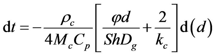
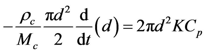
A solid particle undergoing a combustion process, Figure 1, takes an elemental time dt to suffer an elemental reduction of its diameter  [22-30],
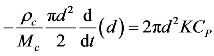 (1)
(1)
and taking into account the overall resistance to combustion 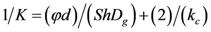
 (2)
(2)
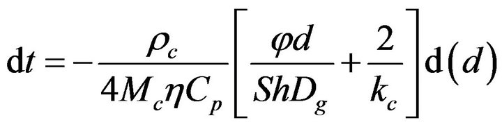
But this particle belongs to a flow of particles that is continuously introduced into the bed and they compete among them for the available oxygen. To account for such competition a multiplying factor  is used for the O2 concentration [44],
 (3)
(3)
A value of  close to one means that the inter particles competition for the available oxygen is small, whereas low values of
  mean low oxygen availability. There is some subjectivity on the choice of
  values, but this it is nonetheless a simple and attractive way to quantify the importance of the easiness of access to the available O2.
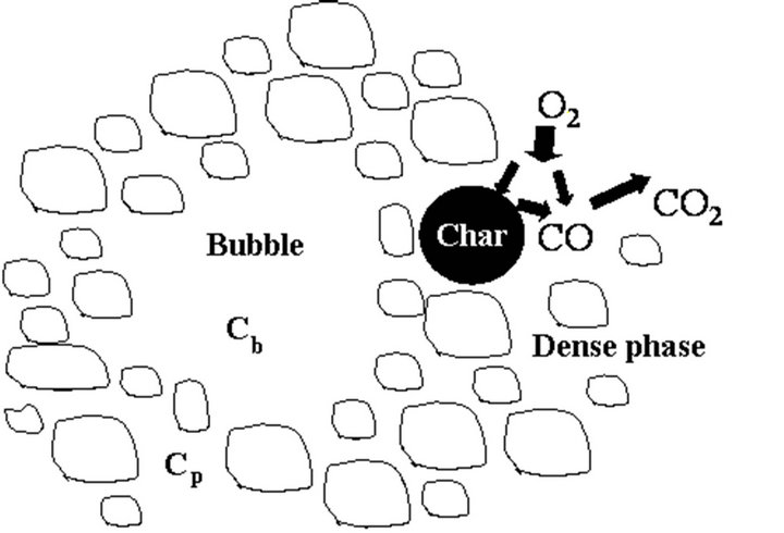
Figure 1. Schematic representation of the combustion of a carbon particle.
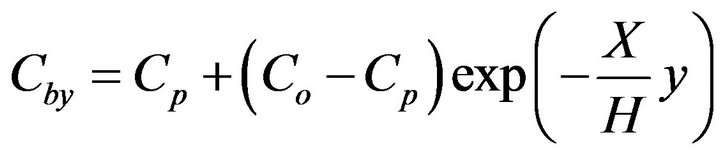
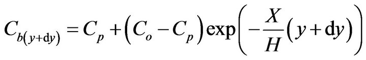
Figure 2 shows the O2 balance inside the fluidized bed. Oxygen enters the bed through the fluidizing air and is distributed into the dense and the bubble phase [45]. In the dense phase the O2 concentration is uniform and equal to , for the bubble phase the oxygen concentration is given by
 (4)
(4)
where  is the number of times the bubble volume is swept during its ascension inside the bed [46]. The dense phase is a uniformly mixed flow reactor while the bubble phase is a plug flow reactor [47]. The particles burn in the dense phase and their burning time is dependent on
 .
.
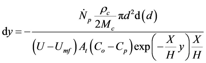
Making an oxygen balance in a slice of fluidized bed with a thickness of dy at level y and looking inside the bubbles there, is then,
 (5)
(5)
while at level ,
,
 (6)
(6)
In this slice of the fluidized bed the O2 inlet minus the outlet will be consumed in the combustion of the particles remaining inside it. As the O2 concentration in the dense phase is constant and equal to , it is only necessary to carry out the oxygen balance of the bubble phase, to determine the oxygen that has been consumed in the combustion of the particles contained inside the bed slice under analysis.
But,
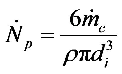
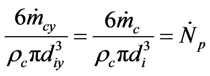 (8)
(8)
is the number of particles introduced in the bed per unit of time, assuming that the solid mass flow is composed of particles of uniform size and that their number stays constant during the combustion process. So, all the particles entering the bed at a given time instant burn at the same combustion ratio.
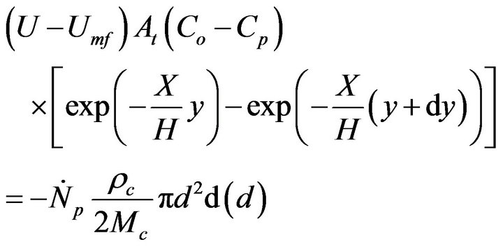
Thus, the O2 balance in the mentioned bed slice is given by,
 (9)
(9)
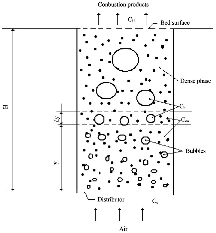
Figure 2. Schematic representation of the fluidized bed reactor.
There is now the following system of equations,
 (10)
(10)
 (11)
(11)
as well,
 (12)
(12)
The set composed by Equations (10) and (11) has no analytical solution. To follow an analytical path, an approximation can be adopted. The difference,
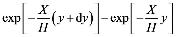 (13)
(13)
can be replaced by
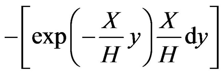 (14)
(14)
with an error of 13% relatively to the results obtained with Equation (13).
The system of equations will now become,
 (15)
(15)
 (16)
(16)
Equation (16) has an analytical solution. Reorganizing and integrating,
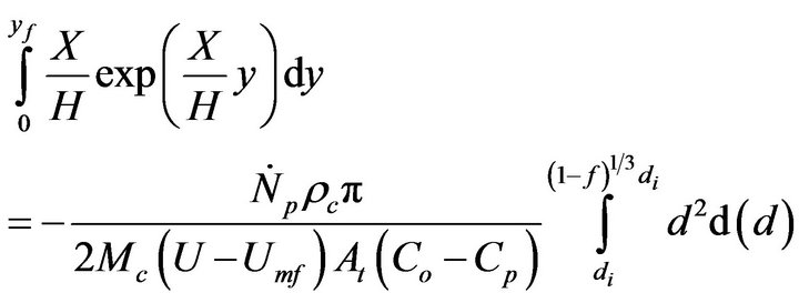 (17)
(17)
it gives the following result,
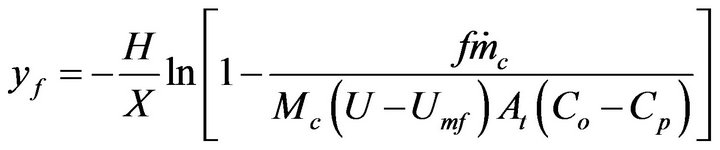 (18)
(18)
Integrating now Equation (15)
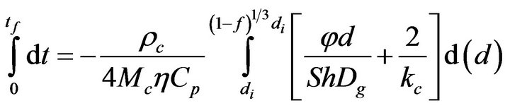 (20)
(20)
it is obtained that,
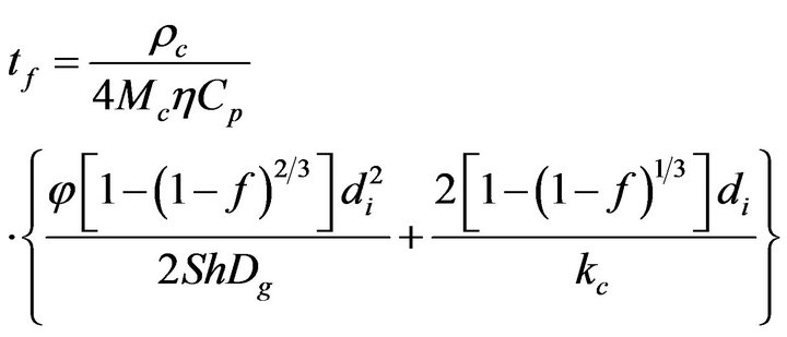 (21)
(21)
This is the combustion time of mass fraction  of a particle from a mass flow of carbon particles introduced in the fluidized bed at the rate of
 . This combustion time is dependent upon the load of particles inside the bed and the bed dimensions and such dependency is implicit in the oxygen concentration in the dense phase
 . If the objective is that the combustion of a mass fraction
  takes place inside the bubbling bed, then Equation (20) with
  is solved in order to get the adequate value of
 ,
,
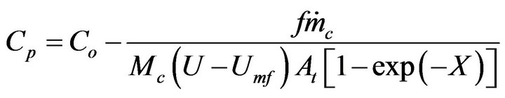 (22)
(22)
Then Equation (22) is introduced into Equation (20) to obtain,
 (23)
(23)
In opposition to the combustion of batches of carbon particles, when the oxygen concentration in the dense phase changes along the combustion time and the bed hydrodynamics term stays in series with the kinetic and the diffusive terms, for the steady state combustion regime, the bed hydrodynamics is superimposed on the kinetic and on the diffusion terms.
In this development and in the subsequent analysis, the mass of a coal particle, or the mass of a batch of particles, or the mass flow rate of coal being introduced inside the bed, will always represent the equivalent carbon value. According to this approach the density of the particles is corrected, by taking into account the corresponding mass fraction of carbon content obtained from the proximate analysis of the chars and thus the particle diameters are kept unchanged.
3. Carbon Inventory of the Bed
When a given mass flow rate of carbon is introduced into the bed it is assumed that all the particles have the same initial diameter . So, all the particles existing inside the bed with the same generic diameter d, will all have the same life time. The mass flow rate of carbon fed into the bed corresponds to the introduction of
  particles/second.
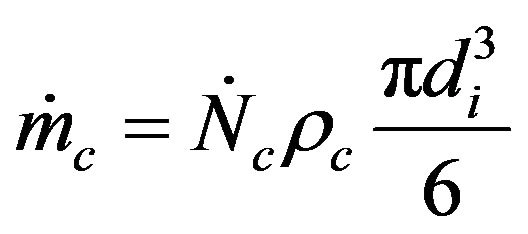 (24)
(24)
and during the life time of these particles , obtained from Equation (21) with
 , many other particles will be entering the bed at the rate of
 , so that the total number of particles existing inside the bed during such time will be of,
 (25)
(25)
and the total mass of carbon remaining inside the bed will be given by
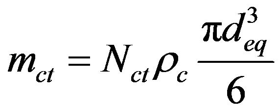 (26)
(26)
The average diameter of the fuel particles inside the fluidized bed , is obtained from the rate of fuel supply which is the same as the combustion rate.
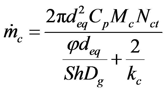 (27)
(27)
4. Analysis of Some Particular Situations
This model will now be applied to the determination of the steady state combustion rate of biomass char in fluidized bed, and the reaction rate constant for the heterogeneous phase reaction , for commercial chars made from nut pine and cork oak, is given by [48],
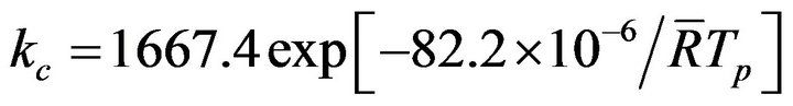 (28)
(28)
valid for the temperature range of 620˚C to 800˚C. The obtained experimental Sherwood numbers were coherent with the values obtained in previous studies of coke combustion [28,49]. Having as general basis these conclusions, as well as the operating conditions typical of the carried out laboratory experiments, it is proposed an analysis of the steady state analysis of the combustion of vegetable chars produced from nut pine and cork oak.
4.1. The Steady State Combustion and the Combustion of Successive Batches of Particles
As the steady state combustion can be approximated by the combustion of successive batches thrown into the bed, it is convenient to compare the combustion results for successive batches with an equivalent steady state situation. Starting from the combustion of successive batches of carbon particles in a bubbling fluidized bed reactor, the ratio between the carbon mass of the batch and the corresponding combustion time gives the mass flow rate of carbon supplied to the bed, which will be equivalent to the carbon bed inflow under steady state operating conditions. The result of the comparison between these two situations can be observed in the next figures. Results in Figure 3 concern particles with an initial diameter of 2 mm burning in a fluidized bed operating at 800˚C, while data in Figure 4 concern 5 mm particles burning in a bed at 750˚C. Table 1 shows the characteristics of the fluidized bed that was adopted for these calculations.
In this first analysis it is not considered a mass flow of carbon enough to guarantee the maintenance of an adequate bed temperature. It is implicit a supplementary heating support to assure the maintenance of the required bed temperature, like in laboratory scale experiments.
Through the comparison between the batch combustion time tbc and the corresponding steady state combustion time tstc, it is possible to verify that the divergence of
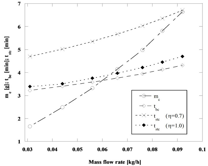
Figure 3. Combustion of batches and steady state combustion of pine nut char particles with 2 mm initial diameter, in a bed at 800˚C and for U/Umf = 7.
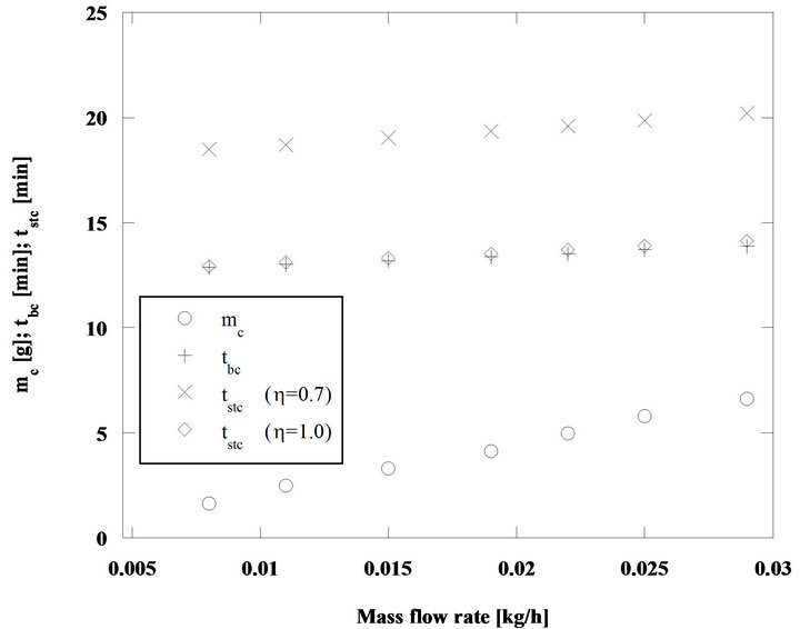
Figure 4. Batch and steady state combustion of pine nut char particles with di = 5 mm, Tb = 750˚C and for U/Umf = 7.
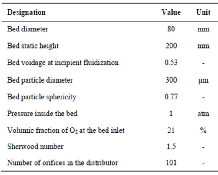
Table 1. Characteristics of the fluidized bed for comparison among batch and steady state combustion.
values goes around 5% to 9% adopting as the correct basis the batch combustion time and assuming a interparticle competition factor for the available oxygen of  in the steady state combustion regime, Figure 3.
In the situation considered in Figure 4 the difference between the two combustion times is smaller, now is of the order of 1% to 2%, when taking as reference the batch combustion time.
It is clear that the model for the steady state combustion allows a good approach for the particle life time of a particle burning inside the bed, when considering as a reference basis the combustion of successive batches of particles.
In Figure 5 it can be seen that between h = 0.6 and 1 there is a 65% reduction on the combustion time of a particle, using the h = 0.6 situation as the reference.
Analyzing now the influence of the bed temperature, keeping the other operating conditions constant (60 g/h of pine nut char, 2 mm initial diameter of fuel particles and U/Umf = 7), the curves shown in Figure 6 were obtained, whereas in Figure 7 burning times for particles with initial diameters between 1 and 5 mm, carbon mass flow rates of 60 and 120 g/h and for a bed temperature of 800˚C, are shown.
The importance of the superficial velocity ratio U/Umf is shown in Figure 8 for combustion at 750˚C and h = 0.7. The influence of this velocity ratio U/Umf is enhanced with the fuel particle diameter, indicating that for smaller particles the combustion reaction is kinetically controlled, while diffusion starts to dominate for larger diameters.
Diffusion and kinetics both compete for the control of the combustion reaction and the relative importance of these two phenomena changes, according to the operating conditions. Figure 9 shows the relative importance of these two phenomena along the development of the combustion process for the combustion of a carbon mass
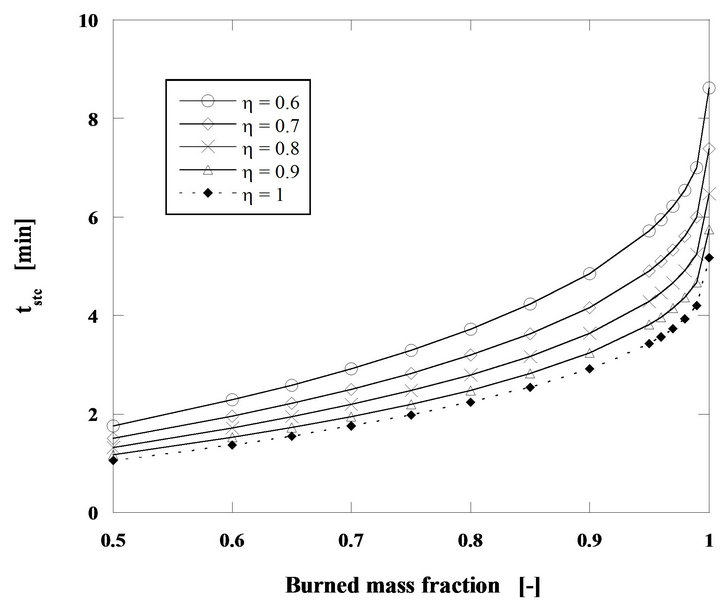
Figure 5. Particle burning time for steady state combustion of a mass flow rate of 60 g/h of pine nut char with 2 mm, for U/Umf = 7 and Tb = 750˚C.
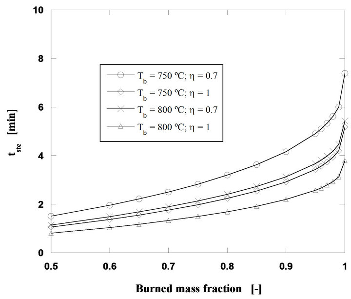
Figure 6. Particle burning time for a mass flow rate of 60 g/h of pine nut char at 750˚C and 800˚C (di = 2 mm and U/Umf = 7).
flow rate of 60 g/h of pine nut char with 5 mm initial diameter in a bed operating at 750˚C and for U/Umf = 15.
Another interesting comparison is the analysis of the relative importance of kinetics and diffusion for cork oak char and for an initial fuel particle diameter of 2 mm, Figure 10. It is now found that in spite of this char being more reactive than the previous one [48], the importance of the smaller initial diameter is the dominant influence and the reaction is always kinetically controlled. The same happens with the pine nut char with di = 2 mm, its lower reactivity makes it even more dependent upon the kinetics and consequently on the combustion temperature.
In Figure 11 the behavior of pine nut and cork oak chars is compared. The cork oak char being less dense,
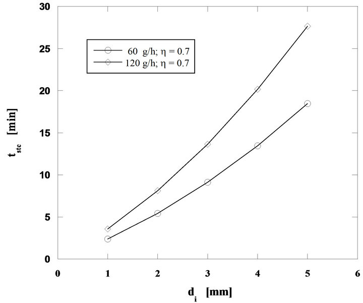
Figure 7. Particle burning time for mass flow rates of 60 and 120 g/h of pine nut char at 800˚C and U/Umf = 7.
Figure 8. Importance of U/Umf upon steady sate particle combustion. Mass flow rate of pine nut char 60 g/h, h = 0.7 and bed temperature of 750˚C.
thus more porous, is more reactive and presents a higher intrinsic area available for the heterogeneous phase reaction leading to shorter combustion times.
In all these plots, Figures 3-11, the calculated results are based on the assumption that both the temperature of burning fuel particles the bed temperature, are identical. As previously said the burning fuel temperature should be about 100˚C above the bed temperature. However such information was obtained at laboratory scale experiments through the study of combustion of batches of particles and there are no data, also at laboratory scale, to get reliable information about particle burning temperatures under steady state conditions. A higher burning temperature means a lesser importance of the kinetic
Figure 9. Relative importance of diffusion and kinetics for the combustion of 60 g/h of pine nut char particles at 750˚C. di = 5 mm, h = 0.7 and U/Umf = 15.
Figure 10. Relative importance of diffusion and kinetics for the combustion of 60 g/h of cork oak char particles at 750˚C. di = 2 mm, h = 0.7 and U/Umf =15.
control. However, in general terms the conclusions drawn from Figures 3-11 remain intact.
4.2. Performance of a Fluidized Bed Burner with 1 m Diameter
The next example is the analysis of the behavior of a larger size bubbling fluidized bed burner, working in steady state and self-sustained combustion of pine nut char. The dimensions and main properties of this reactor are presented in Table 2.
There are other basic assumptions adopted for the present development, which must now be stressed, because for a self-sustained combustion the amount of thermal energy released by the combustion reaction taking place
Figure 11. Steady state combustion of pine nut and cork oak char. Mass flow rate of 60 g/h, initial particle size of 2 mm and U/Umf = 7.
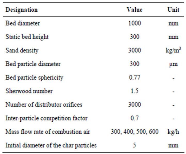
Table 2. Dimensions and main properties of a 1 m diameter reactor.
inside the bubbling bed must be carefully accounted for in order to assure a proper combustion temperature:
• The bed confining walls are refractory and adiabatic and the bed does not lose heat through radiation heat transfer from its free surface;
• Losses through unburned fine particles elutriated from the bed are neglected. In practical terms this approach makes sense as fluidized bed burners are usually equipped with cyclonic separation systems in order to collect unburned solid particles reintroducing them into the bed;
• The primary fragmentation of the fuel particles occurring at the moment of their introduction into the bed is neglected;
• Fuel particles burn at the uniform bed temperature;
• The inlet air flow is at 25˚C and 1 atm.
In Figure 12 results from the application of this model to the four mass flow rates of combustion air presented in Table 2 are plotted. The burner is fed with ambient air (21% (v/v) O2) and works at atmospheric pressure. It is assumed that the CO formed by the heterogeneous phase reaction at the surface of the particles will lately burn away from them, but inside the bed [28,29,50].
The results in Figure 12 show the particle burning time in a steady state combustion process tstc, and the evolution of the bed temperature as a function of the nut pine char mass flow rate, effective carbon mass flow rate. Figure 13, presents the curves corresponding to the thermal power being released through the char particles combustion process, assuming a lower calorific value for de carbon of 32,794 kJ/kg. The evolution of U/Umf is also plotted in the figure.
Finally Figure 14, presents the instantaneous inventtory of carbon mass in the bed as well as the evolution of the oxygen volumic fraction inside the dense phase of the bed, whose values change from 13% to 14.7%. All these tendencies are plotted as a function of the equivalent carbon mass flow rate fed into the bed. The decomposition of these calculations results in four well defined fuel mass flow ranges; equivalent carbon mass flow rates from 6.5 to 8 kg/h, from 8.6 to 10.1 kg/h, from 11 to 12.6 kg/h and finally from 13.1 to 15.2 kg/h, for a constant mass flow rate of fluidizing air for each fuel flow range. This shows in a simple and clear way the dependence between the bed operating conditions and the combustion regime. In these three figures the mass flow rates of 300,
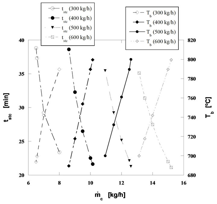
Figure 12. Steady state combustion of pine nut char. Bed diameter 1 m. Static bed height 0.3 m. Bed particle size 300 μm. Initial diameter of char particles, 5 mm.
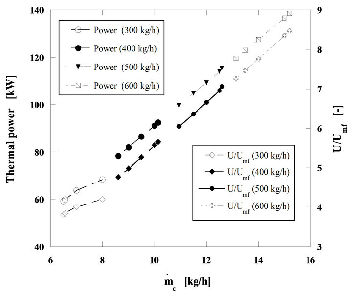
Figure 13. Steady state combustion of pine nut. Bed diameter 1 m. Static bed height 0.3 m. Bed particle size 300 μm. Initial diameter of char particles, 5 mm.
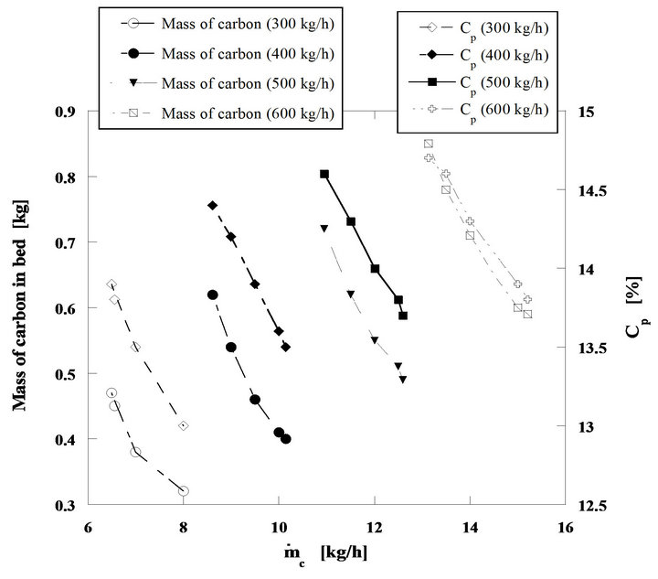
Figure 14. Steady state combustion of pine nut char. Bed diameter 1 m. Static bed height 0.3 m. Bed particle size 300 μm. Initial diameter of char particles, 5 mm.
400, 500 and 600 kg/h refer to the air mass flow rates necessary to establish the four operating regimes previously referred.
According to the carbon inventory in the bed, its value is always below to1 kg for all analyzed situations, while the total mass of the bed sand is of 332 kg, thus the carbon mass fraction inside the bed is always lower than 0.3%.
In Figure 15 results of the bed behavior in a situation closer to reality are presented because in practical terms the control systems adjust the fuel and comburent flows in order to keep the bubbling bed temperature inside close limits previously defined by the operator. For this
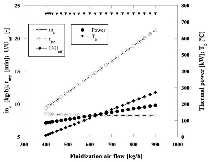
Figure 15. Steady state combustion of pine nut char. Bed diameter 1 m. Static bed height 0.3 m. Bed particle size 300 μm. Initial diameter of char particles, 5 mm.
case the working conditions are in general those of Table 2, with some slight changes that will be presented next.
This Figure 15 shows the performance of the fluidized bed burning nut pine char in steady state regime. Particles have an initial diameter of 2 mm and the bed temperature is of 750˚C. The mass flow rates of fluidizing air and fuel increase in order to keep the bed operating temperature in 750˚C. The thermal power released during the combustion process goes from 86 to 194 kW, when the fuel mass flow rate (as carbon equivalent value) raises from 9.4 to 21.3 kg/h, while the mass flow rate of the fluidizing air goes from 400 until 900 kg/h.
There is a minor reduction of the particle burning time because for this initial size the combustion is kinetically controlled, see Figure 10, and as the bed temperature stays constant the particle combustion time barely changes. Also from this Figure 15 it can be seen that the ratio U/Umf changes from 5.2 to 11.8, and the maximum value is still far away from the ratio Ut/Umf corresponding to the bed sand particles which is 26.4, meaning that the elutriation of the bed sand particles is negligible. The same cannot be said about the fuel particles, because of their lower density they will be easily dragged out of the bed in the fluidizing and combustion gases flow. However such event was not accounted for in the present simulation. In real systems solid unburned particles are captured by cyclonic systems placed in the exhaust section of the boilers or furnaces and are reintroduced back in the bed. As such, in a simple approach this can be done by simply ignoring this elutriation, capture and reintroducing sequence, as if fuel particles were never elutriated away from the bed.
The particle combustion time follows a very interesting path for the range of operating conditions considered.
For this particle size, type of char and bed temperature, the kinetics has some supremacy on the reaction control although there is also some influence of the bed hydrodynamics superimposing itself upon the competition between kinetics and diffusion. At the beginning of the combustion regime being analyzed, the burning time decreases with the increase of the fluidizing air mass flow rate, even if the carbon inventory in the bed is also increasing, but around 700 kg/h of fluidizing air mass flow, the combustion time stabilizes. In this situation the combustion reaction is being controlled by the kinetics and the combustion time does not change because there is no change on the bed temperature, Figure 16.
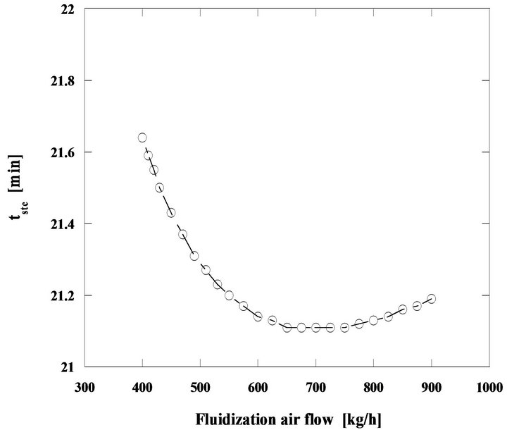
Another situation is the steady state combustion of the same pine nut char but with 5 mm initial diameter particles in a bed operating at 800˚C, so that the importance of diffusion on the control of the combustion is now enhanced, Figures 17 and 18.
Comparing Figures 16 and 18, it is found that for the second case the particle burning time suffers an initial reduction but then after reaching a minimum value it starts increasing. The initial decrease of the combustion time, is the result of the increase of the mass transfer rate with the augmentation of the mass flow of fluidizing air. From 650 to 750 kg/h the combustion time stays approximately constant, two contradictory effects are acting against each other, the diffusion and the fact that there is an increase of carbon inventory in the bed, which leads to an increase of the combustion time. When the weight of the increase of carbon inventory in the bed starts dominating, the combustion time increases, from 750 kg/h of fluidizing air mass flow and beyond. These time changes are however small, of the order of tenths of minutes.
5. Conclusions
Through the study of the steady state combustion of char
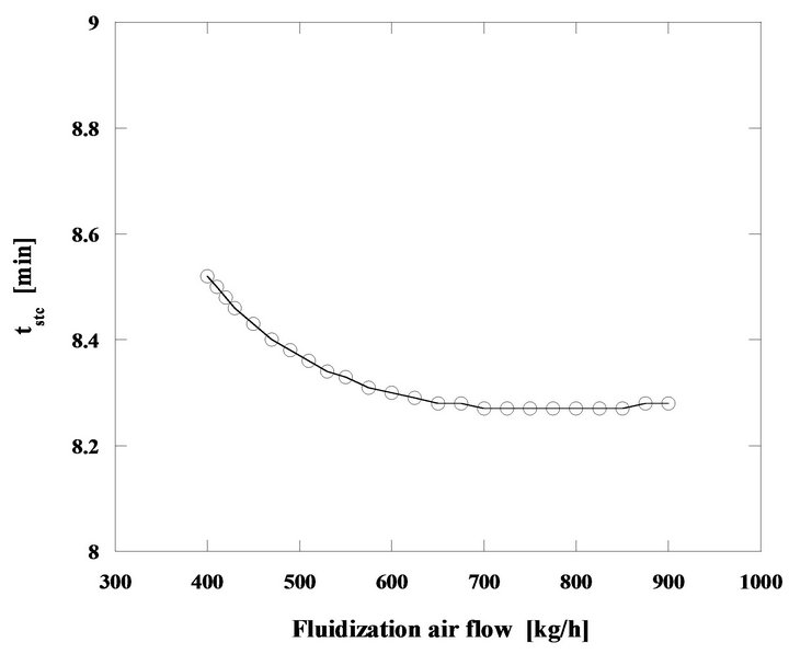
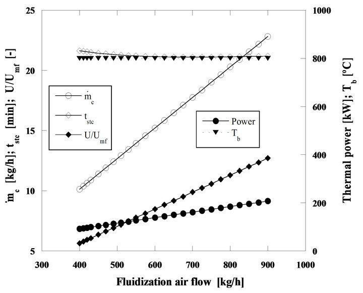
Figure 17. Steady state combustion of pine nut char. Bed diameter, 1 m and 0.3 m of static bed height. Sand particle size, 300 μm. Initial diameter of the char particles, 5 mm. Bed operating temperature, 800˚C.
particles in a bubbling fluidized bed reactor it is shown that:
• Starting with the experimental data obtained in laboratory scale studies of batch combustion of char particles such information about the kinetic and diffusive is adequate for the understanding of the performance of the same type of burners working in steady state conditions;
• It is possible to evaluate the relative importance of kinetics and diffusion for the control of the combustion reaction;
• It is possible by means of a simple mathematical model to carry out a primary design of this type of burners. The simple approach considered in this text allows, because of its simplicity, a quick understanding of the relative importance of the controlling mechanisms upon the combustion reaction;
• The pre-design approach allowed by this simplified method allows the designer to reach important clues for a subsequent deeper design approach.
REFERENCES
- G. P. Hammond and A. J. Stapleton, “Exergy Analysis of the United Kingdom Energy System,” Proceedings of the Institution of Mechanical Engineers, Part A: Journal of Power and Energy, Vol. 215, No. 2, 2001, pp. 141-162.
- I. Obernberger, “Decentralized Biomass Combustion: State of the Art and Future Development,” Biomass and Energy, Vol. 15, No. 1, 1998, pp. 33-56.
- A. Strehler, “Technologies of Wood Combustion,” Ecological Engineering, Vol. 16, Suppl. 1, 2000, pp. S25-S40. doi:10.1016/S0925-8574(00)00049-5
- P. McKendry, “Energy Production from Biomass (Part 1): Overview of Biomass,” Bioresource Technology, Vol. 83, No. 1, 2002, pp. 37-46. doi:10.1016/S0960-8524(01)00118-3
- P. McKendry, “Energy Production from Biomass (Part 2): Conversion Technologies,” Bioresource Technology, Vol. 83, No. 1, 2002, pp. 47-54. doi:10.1016/S0960-8524(01)00119-5
- P. McKendry, “Energy Production from Biomass (Part 3): Gasification Technologies,” Bioresource Technology, Vol. 83, No. 1, 2002, pp. 55-63. doi:10.1016/S0960-8524(01)00120-1
- J. G. Speight, “Synthetic Fuels Handbook. Properties, Process and Performance,” McGraw-Hill, New York, 2008.
- S. C. Bhattacharya, “State of the Art of Biomass Combustion,” Energy Sources, Vol. 20, No. 2, 1998, pp. 113- 135. doi:10.1080/00908319808970051
- G. Grassi, “Modern Bioenery in the European Union,” Renewable Energy, Vol. 16, No. 1-4, 1999, pp. 985-990. doi:10.1016/S0960-1481(98)00347-4
- L. Núñez-Regueira, J. A. Rodríguez-Añón and J. ProupínCastiñeiras, “Calorific Values and Flammability of Forest Species in Galicia. Continental High Mountainous and Humid Atlantic Zones,” Bioresource Technology, Vol. 61, No. 2, 1997, pp. 111-119. doi:10.1016/S0960-8524(97)00053-9
- L. Núñez-Regueira, J. Rodríguez, J. Proupín and B. Mouriño, “Forest Waste as an Alternative Energy Source,” Thermochimica Acta, Vol. 328, No. 1-2, 1999, pp. 105-110. doi:10.1016/S0040-6031(98)00630-3
- L. Núñez-Regueira, J. A. Rodríguez-Añón, J. ProupínCastiñeiras, A. Vilanova-Diz and N. Montero-Santoveña, “Determination of Calorific Value of Forest Waste Biomass by Static Bomb Calorimetry,” Thermochimica Acta, Vol. 371, No. 1-2, 2001, pp. 21-31.
- L. Núñez-Regueira, J. A. Rodríguez-Añón, J. ProupínCastiñeiras and O. Núñez-Fernández, “Calculation of Forest Biomass Indices as a Toll to Fight Fores Fires,” Thermochimica Acta, Vol. 378, No. 1-2, 2001, pp. 9-25. doi:10.1016/S0040-6031(01)00591-3
- European Environment Agency, “How Much Bioenergy Can Europe Produce without Harming the Environment?” EEA Report 7/2006, Copenhagen, 2006.
- G. Boyle, “Renewable Energy. Power for a Sustainable Future,” The Open University, Milton Keynes, 1986.
- N. El Bassam, “Energy Plant Species. Their Use and Impact on Environment and Development,” James and James (Science Publishers) Ltd., London, 1998.
- D. L. Klass, “Biomass for Renewable Energy, Fuels and Chemicals,” Academic Press, San Diego, 1998.
- J. Werther, M. Saenger, E. U. Hartge, T. Ogada and Z. Siagi, “Combustion of Agricultural Residues,” Progress in Energy and Combustion Science, Vol. 26, No. 1, 2000, pp. 1-27. doi:10.1016/S0360-1285(99)00005-2
- A. Demirbas, “Combustion Characteristics of Different Biomass Fuels,” Progress in Energy and Combustion Science, Vol. 30, No. 2, 2004, pp. 219-230. doi:10.1016/j.pecs.2003.10.004
- C. Descamps, C. Bouallou and M. Kanniche, “Efficiency of an Integrated Gasification Combined Cycle (IGCC) Power Plant including CO2 Removal,” Energy, Vol. 33, No. 6, 2008, pp. 874-881. doi:10.1016/j.energy.2007.07.013
- S. Oka, “Fluidized Bed Combustion,” Marcel Dekker, Inc., New York, 2004.
- M. M. Avedesian and J. F. Davidson, “Combustion of Carbon Particles in a Fluidised Bed,” Transactions of the Institution of Chemical Engineers, Vol. 51, 1973, pp. 121- 131.
- H. A. Becker, J. M. Beer and B. M. Gibbs, “A Model for Fluidized-Bed Combustion of Coal,” Institute of Fuel Symposium Series No. 1: Fluidised Combustion, 1975, pp. A1-1-A1-10.
- I. B. Ross and J. F. Davidson, “The Combustion of Carbon Particles in a Fluidised Bed,” Transactions of the Institution of Chemical Engineers, Vol. 59, 1981, pp. 108- 114.
- I. B. Ross, M. S. Patel and J. F. Davidson, “The Temperature of Burning Carbon Particles,” Transactions of the Institution of Chemical Engineers, Vol. 59, 1981, pp. 83-88.
- C. M. C. T. Pinho and J. R. F. Guedes de Carvalho, “The Combustion of Coke Particles in a Fluidised Bed. Some Aspects of Kinetic Data Collection,” I. Chem. E. Symposium Series, No. 87, 1984, pp. 77-84.
- A. N. Hayhurst, “Does Carbon Monoxide Burn inside a Fluidised Bed? A New Model for the Combustion of Coal Char Particles in Fluidised Beds,” Combustion and Flame, Vol. 85, No. 1-2, 1991, pp. 155-168. doi:10.1016/0010-2180(91)90184-D
- J. R. F. Guedes de Carvalho, A. M. F. R. Pinto and C. M. C. T. Pinho, “Mass Transfer around Carbon Particles Burning in Fluidised Beds,” Transactions of the Institution of Chemical Engineers, Vol. 69, No. 1, 1991, pp. 63-70.
- O. D. S. Mota, A. M. F. R. Pinto and J. B. L. M. Campos, “Fluidised-Bed Combustion of a Charge of a Coke with a Wide Distribution of Particle Sizes,” Chemical Engineering Science, Vol. 49, No. 8, 1994, pp. 1097-1105. doi:10.1016/0009-2509(94)85082-8
- A. N. Hayhurst and M. S. Parmar, “Does Solid Carbon Burn in Oxygen to Give the Gaseous Intermediate CO or Produce CO2 Directly? Some Experiments in a Hot Bed of Sand Fluidised by Air,” Chemical Engineering Science, Vol. 53, No. 3, 1998, pp. 427-438. doi:10.1016/S0009-2509(97)00334-5
- L. Ribeiro and C. Pinho, “Generic Behaviour of Propane Combustion in Fluidized Beds,” Chemical Engineering Research and Design, Vol. 82, No. 12, 2004, pp. 1597- 1603. doi:10.1205/cerd.82.12.1597.58039
- L. Ribeiro, and C. Pinho, “Combustion of Slugs of Propane and Air Moving through an Incipiently Fluidized Bed,” Combustion Theory and Modelling, Vol. 11, No. 3, 2007, pp. 401-425.
- J. S. M. Botteril, “Fluid-Bed Heat Transfer,” Academic Press, London, 1975.
- F. Scala and R. Chirone, “Combustion and Attrition of Biomass Chars in a Fluidized Bed,” Energy and Fuels, Vol. 20, No. 1, 2006, pp. 91-102. doi:10.1021/ef050102g
- S. C. Bhattacharya and W. Z. Wu, “Fluidized Bed Combustion of Rice Husk Disposal and Energy Recovery,” Energy from Biomass and Wastes Symposium, Institute of Gas Technology, New Orleans, 1988.
- D. A. Tillman, A. J. Rossi and W. D. Kitto, “Wood Combustion: Principles, Process and Economics,” Academic Press, San Diego, 1981.
- L-E. Åmand and B. Leckner, “Co-Combustion of Sewage Sludge with Wood/Coal in a Circulating Fluidized Bed Boiler—A Study of Gaseous Emissions,” 1st Biennial Meeting of the Scandinavian-Nordic Section of the Combustion Institute, Chalmers University of Technology. Göteborg, 18-20 April 2001.
- L-E, Åmand, H. Miettinen-Westberg, M. Karlsson, B. Leckner, K. Lucke, S. Budinger, E. U. Hartge and J. Werther, “Co-Combustion of Sewage Sludge with Wood/ Coal in a Circulating Fluidized Bed Boiler—A Study of NO and N2O Emissions,” 3rd International Symposium on Incineration and Flue Gas Treatment Technologies, Brussels, 2-4 July 2001, p. Session 5.
- W. C. Yang, “Handbook of Fluidization and Fluid-Particle Systems,” Marcel Dekker, Inc., New York, 2003. doi:10.1201/9780203912744
- J. C. Roscoe, A. R. Witkowski and D. Harrison, “The Temperature of Coke Particles in a Fluidised Combustor,” Transactions of the Institution of Chemical Engineers, Vol. 58, 1980, pp. 69-72.
- J. Adánez, F. de Diego, F. García-Labiano, A. Abad and J. C. Abanades, “Determination of Biomass Char Combustion Reactivities for FBC Applications by a Combined Method,” Industrial & Engineering Chemistry Research, Vol. 40, No. 20, 2001, pp. 4317-4323. doi:10.1021/ie0102394
- Y. H. Khraisha, “Batch Combustion of Oil Shale Particles in a Fluidized Bed Reactor,” Fuel Processing Technology, Vol. 86, No. 6, 2005, pp. 691-706. doi:10.1016/j.fuproc.2004.07.002
- M. Komatina, V. Manovic and D. Dakic, “An Experimental Study of Temperature of Burning Coal Particle in Fluidized Bed,” Energy and Fuels, Vol. 20, No. 1, 2006, pp. 114-119. doi:10.1021/ef050222o
- K. Annamalai, “Interactive Processes in Evaporation and Combustion of Liquid Drop Arrays and Clouds,” In: H. H. Chiv and N. Chigier, Eds., Mechanics and Combustion of Droplets and Sprays, Begell House, Inc., New York, 1995, pp. 116-160.
- J. F. Davidson and D. Harrison, “Fluidised Particles,” Cambridge University Press, Cambridge, 1963.
- S. Hovmand, W. Freedman and J. F. Davidson, “Chemical Reaction in a Pilot-Scale Fluidized Bed,” Transactions of the Institution of Chemical Engineers, Vol. 49, 1971, pp. 149-162.
- T. G. Dobre and J. G. Marcano, “Chemical Engineering. Modelling, Simulation and Similitude,” Wiley-VCH Verlag GmbH & Co. KGaA, Weinheim, 2007.
- N. A. R. Moreira, “Characterization of the Combustion of Vegetable Chars in Fluidized Bed (In Portuguese-Caracterização da Combustão de Carvões Vegetais em Leito Fluidizado),” Ph.D. Thesis, University of Oporto, Porto, 2008.
- R. D. La Nauze, K. Jung and J. Kastl, “Mass Transfer to Large Particles in Fluidised Beds of Smaller Particles,” Chemical Engineering Science, Vol. 39, No. 11, 1984, pp. 1623-1633. doi:10.1016/0009-2509(84)80089-5
- P. S. Fennell, S. Kadchha, H.-Y. Lee, J. S. Dennis and A. N. Hayhurst, “The Measurement of the Rate of Burning of Different Coal Chars in an Electrically Heated Fluidised Bed of Sand,” Chemical Engineering Science, Vol. 62, No. 1-2, 2007, pp. 608-618. doi:10.1016/j.ces.2006.09.024
Notation