Energy and Power Engineering
Vol. 4 No. 2 (2012) , Article ID: 18023 , 8 pages DOI:10.4236/epe.2012.42011
The Application of Radiation Shields for Thermal Control of Superheater Tubes in Boiler
1Department of Mechanical Engineering, Langrud Branch, Islamic Azad University, Langrud, Iran
2Department of Mechanical Engineering, Roudsar-Amlash Branch, Islamic Azad University, Roudsar, Iran
Email: {Falahatkar.sh, T_pourreza}@iaul.ac.ir, habib_karimi63@yahoo.com
Received December 13, 2011; revised January 20, 2012; accepted January 30, 2012
Keywords: Platen Superheater; Heat Transfer; Combustion; Radiation Thermal Shields; Boiler; CFD
ABSTRACT
Superheater tubes temperature control is a necessity for long lifetime, high efficiency and high load following capability in boiler. This study reports a new approach for the control strategy design of boilers with special shields. The presented control strategy is developed based on radiation thermal shields with low emissivity coefficient and high reflectivity or scattering coefficient. In order to simulate the combustion event in boiler and heat transfer to superheater tubes, an effective set of computational fluid dynamic (CFD) codes is used. Results indicate a successful identification of overheated zones on platen superheater tubes and effect of radiation shields for solving this problem.
1. Introduction
The quick and vast development of the numerical techniques and software abilities can presently take advantage of highly sophisticated engineering techniques, such as CFD (computational fluid dynamics) calculations. The use of CFD codes for modeling of combustion, heat and fluid flow is a useful tool to predict the performance of boilers among the scientific and industrial communities. Numerous sub-models for simulating in the furnace processes such as combustion, the conduction, convection and radiation modes of heat transfer and chemical reaction have been developed by researchers.
However, because of the expensive cost measurements of the combustion and heat transfer characteristics and limitation of measurements in this type of process a few experimental works were reported in the literature. For a good simulation of boiler, we have to solve fluid flow equations, radiation equations, transport turbulent equations and chemical reaction equations. As the temperature inside the boiler is high, the measurement tools could not be used to show the fluid specification and utility inside the steam product of boiler. Therefore, using the CFD in modeling this type of utility and processes are well known.
In investigation for using the CFD in the boilers modeling, a model was developed on the base of CFD technique for a waste heat recovery boiler by Manickam et al. [1]. The boiler fuel was a typical plant off gas consisting of both gaseous and particulate combustibles. The model allowed the calculation of the temperature of gas and particles within the boiler. In respect to this compute technique, Vafin and Abduliin [2] investigated the radiation heat transfer to these tubes from the combustion chamber in which there were water wall tubes. Rahimi et al. [3], modeled the boiler of Biston power plant, Kermanshah, Iran, and investigated the radiation heat transfer to the two rows of the superheater tubes as well as a micro structural and metrological investigation. A numerical simulation of the flow and combustion process in the furnace of a pulverized coal fired 350 MW utility boiler was presented by Xu et al. [4]. In that study, the boiler contains 24 swirl burners installed at the furnace front wall. The predicted results were compared with the plant data. A reasonable agreement between the site data and simulation results was reported by the authors.
In the present work, the 320 MW boiler of Isfahan power plant, Isfahan, Iran, was modeled with using the CFD technique. The main aim of this modeling is to find the reason for the tubes rupture inside the boiler. The study more focused on heat transfer to the superheater tubes and the temperature field on tubes besides other transport phenomena calculations.
2. Boiler and Its Attachments
According to the data on the boiler of the 4th unit of Isfahan’s power plant, a 320 (MW) boiler was analyzed in real scale. According to the complete map of the studied boiler (Isfahan Power plant Documents 2009) [5], the length, width and height of the boiler were presumed 10.458 m, 11.658 m and 39.774 m respectively.
The aforementioned boiler contained 16 gas burners with the capacity of using crude oil as the second fuel. These burners are located in four rows through the sides of the boiler. For more details, an overall view of the modeled power plant boiler is sketched in Figure 1. The burners of each rows of the boiler assembled with the angles of 37˚ and 46˚ of their lateral surfaces. This arrangement contributes to the formation of fire vortex in an effective way. This boiler has a drum with the feature of one-stage reheat and is designed with the capability of burner angle variation from 0 to 30 degrees to the horizon. The volume of this boiler is about 4700 cubic meters and the steam generation capacity in this boiler equals to 1056 tons/hour in the maximum work load. Each burner contains two gas nozzles and three air channels. In order to mix of gas with air in this boiler, gas nozzles, the upper and lower air channels in each flat of the boiler burners is adjusted to the angles of 5 and –5 to the surface of horizon. Figure 2 is depicted to provide more information with respect to one of the flats where a burner is located and introduce the modality of air channels’ arrangement
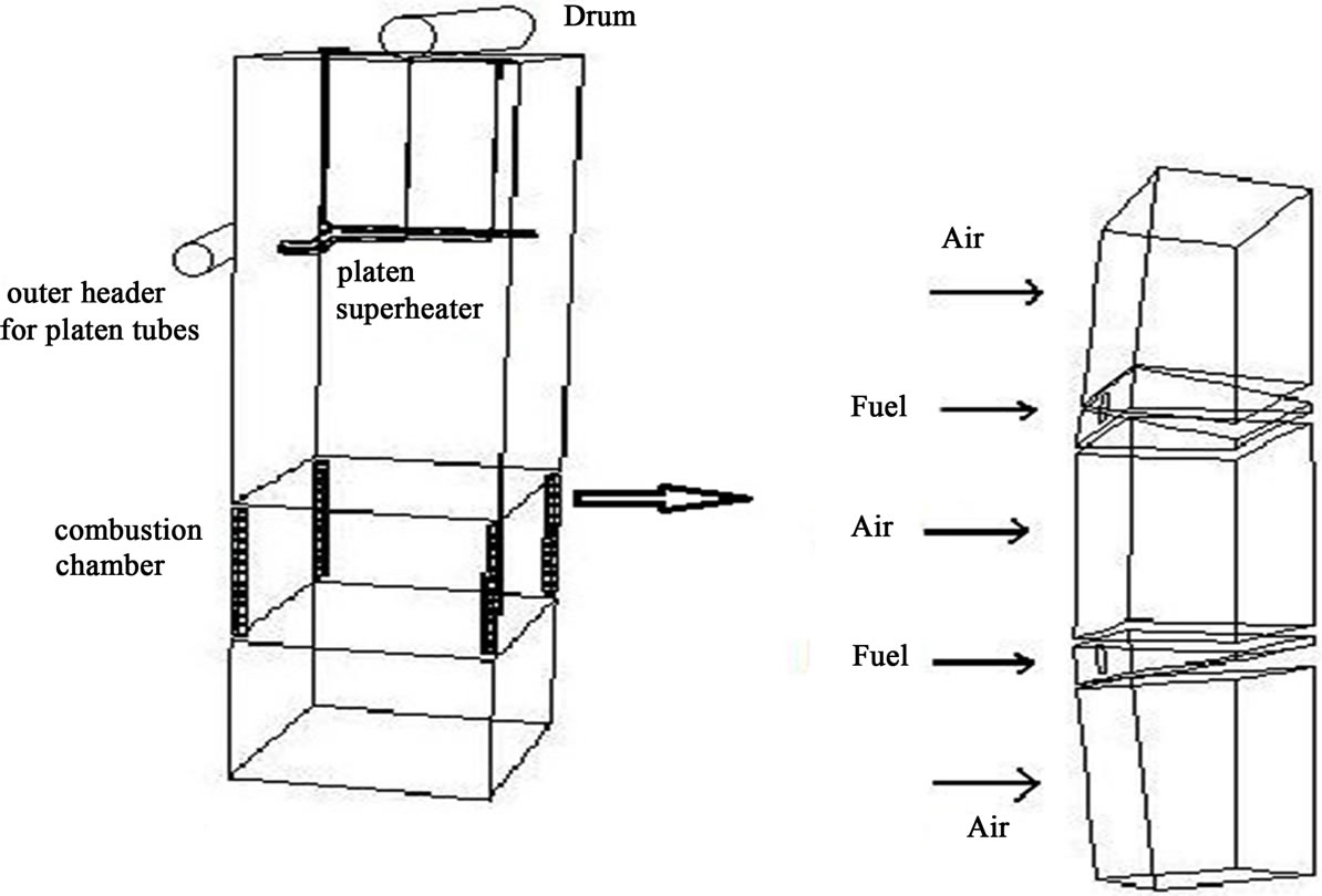
Figure 1. An overall view of the analyzed boiler.

Figure 2. Gas nozzles and air channels in each flat of the burners.
and fuel nozzles in each flat, as well. Based on the data provided by the power plant, the rate of flow of each air channel stands at approximately 5.6 kg/s and each gas nozzle at approximately 0.47 kg/s. The inlet pressure would be considered to be atmospheric. The temperature of inlet methane would be approximately 300 K and the temperature of the inlet air is about 600 K. The boiler has six banks of the superheaters tubes in three categories. Platen superheater region including: dual long tubes, dual medium tubes and dual short length tubes. The tubes were made from 14Cr5Mo stainless steel with an outer diameter of 0.038 m and an inner diameter of 0.028 m. A saturated steam with a pressure of 18.9 MPa from drum enters to the header box and after distributing in the tubes, it heats inside the boiler by all modes of heat transfer. Finally the steam is diverted from the platen superheater tubes into the junction header and collected.
3. Main Reasons for the Tubes Damage
The output steam of drum has to include more temperature to have more energy, this term called dry steam or superheat steam. This action is done inside the superheater which located as parallel tubes and on street of the hot gases resulting from combustion. These tubes transfer the heat resulting from combustion products to the steam. Then changing saturation steam into the superheat steam, the tubes make them ready to be transferred to high pressure floor of Turbin. In major power plants, rupture and bending along these tubes are one of the common problems reported that the boiler stops from the units of production line.
By inspection of these tubes, we have to study several parameters that there are in the inner space of boiler. This parameters including: Stress, fatigue, corrosion or erosion. Pollution region resulting from combustion and fast movement of superheat steam in the platen superheater tubes are main reasons for creation corrosion and fatigue on these tubes [6]. But based on the references [2,3], by focus on these tubes, no considerable reduction in the tube thickness observed. Therefore, the corrosion or erosion and fatigue and consequent reduction in the tube thickness cannot be the main reason for tube damage. In this study, primitive results show overheated phenomena on a series of elbows belongs to the long and medium tubes near the outlet header of platen superheater. This notice shows a reasonable agreement between the common reports of power plants and this simulation results. Hence, In this research, we focused on the thermal stress on the tubes. if an unconstrained tube is heated, its length will increase equal to αΤΔL. But when superheater tubes as a constrained tube is heated, a large thermal stress will make in these tubes. Therefore temperature of these tubes and large difference with design temperature is a main reason for rupture on the superheater tubes.
4. Governing Equations and CFD Work
The studied boiler was divided into more than 1.5 million control volumes with a quadrilateral or pyramidical geometry after being modeled with the real scales. Therefore, the boiler geometry was prepared for the numerical analysis. Computational Fluid Dynamic (CFD) method was used for the numerical analysis. In the majority of codes oriented on the CFD method, Reynolds and Navier-Stokes equations were used for remodeling the current [7] where defining the average time dependant properties for the current helps define the average time dependant Navier-Stokes equations as follow:
Continuity equation: This equation for gas mixture may be written in the form of:
 (1)
(1)
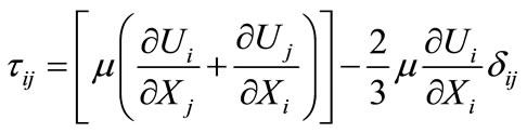
Navier-Stokes equations: The momentum conservation equation is the Navier-Stokes equation:
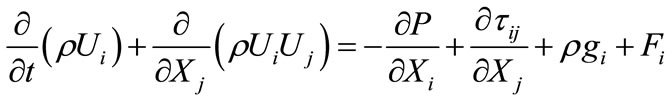 (2)
(2)
Here  is the tensor of stress:
 (3)
(3)
In order to model the turbulences governing on the current, the two-equation model of K and ε was employed accordingly [8]. This model includes the solution of transfer equations for the turbulence kinetic energy of K and its loss as ε.
Transport equations for kinetic energy (K):
 (4)
(4)
Transport equations for loss of energy (ε):
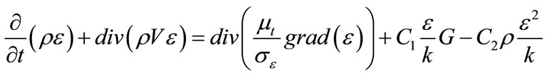 (5)
(5)
Eddy dissipation model was employed for the combustion calculations [9]. This model is predicated on the low-speed models and was first developed by [8]. In the relevant code of this method, the speed of reaction’s progress in turbulent combustion will be attributed to the failure of vortexes and the blend of their classes. It is presumed in this model that the fuel and oxidant come in separate vortexes in turbulent currents and they are mixed when the larger vortexes are turned into smaller ones and the smaller vortexes are disappeared as a result of viscosity in a way that the fuel and oxidant can be mixed. This model contains the solution of components’ transfer equations as follows.
Conservation equation for species:
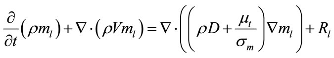 (6)
(6)
In the above equation, R stands for the speed of fuel consumption which will be defined on the basis of fuel vortexes’ disappearance or oxygen vortexes’ disappearance as follows:
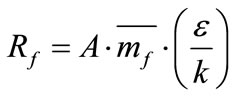 (7)
(7)
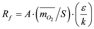 (8)
(8)
The value of Rf would be resulted from the two equations above and the smallest value will be used in the calculations.
The total equation of energy is written in the form of:
 (9)
(9)
Radiation Transfer Equation (RTE) for a gray environment at S-direction would be written as follows:
 (10)
(10)
In order to solve the RTE, the P-1 radiation model was employed. For calculating the radiation properties of the mixture resulting from combustion, the weighted sum of gray gases model (WSGGM) was used. In order to create an accurate relationship between the pressure and speed in the continuity and momentum equations, the SIMPLE method was used. Solution algorithm was also oriented on the segregated solver. Applying the relevant equations and proper models to solve them in the calculative slope of the studied boiler (with real dimensions) was the first step. Then, the identification of boundary conditions of the analysis slope was taken into consideration according to the data gathered from the power plant. Then, with the observation of convergence in the answers, the primary results of simulation were produced.
5. Results
After carried out the 800 computational iterations and convergence of the equations answer, temperature of the products resulting from combustion inside the boiler reaches about 2340 K. Figure 3 demonstrates fire vortex inner of boiler.
Following the examination of combustion process inside the boiler, the thermal analysis of platen superheater tubes as the first set of superheater tubes which are exposed to a broad spectrum of flames resulting from combustion, was put into agenda. All the three types of platen superheater tubes with long, medium and short lengths were analyzed from the view of their length. Platen superheaters comprise three set of twin tubes and each set constitute a single row of tubes and each row contains 100 tubes. As said earlier, the main part of heat transfer in the platen superheaters is of the radiation sort, for the reason that they are located in the nearest distance to the burners in compare with the rest of superheater tubes, and also the convection heat transfer coefficient of the vapor in these tubes is low. The saturated vapor with temperature of 357˚C and pressure of 18.94 MPa flows into the platen superheater tube from the upper header box. The superheat vapor flowing in these helical tubes undergoes a fall of pressure until reaching the pressure of outlet header box equal to 17.73 MPa. However, the fall of pressure through each tube varies according to its length and its proportional knee. In the consequential results of simulation, all the three rows of studied tubes realized the pressure of outlet header box with a proper accurate. Considering the CFD calculations of this study, 38% of the inlet vapor passes through the short tubes, 34% moves across the medium tubes and 28% traverses the long tubes; therefore, the reported mass flow rate for the short, medium and long tubes stood at about 1.12, 1.01 and 0.81 kg/s respectively.
Following this conclusion, the average speed of vapor in these three tubes would be different with together. Based on the results of the present research, the average speeds of vapor in these tubes, 19.3 m/s, 17.5 m/s and 14.2 m/s were reported for the short, medium and long tubes respectively. As the mass flow rate in the short tubes is more than of medium and long tubes which causes the speed of vapor in short tubes to be consequentially more than speed of vapor in medium and long tubes, the value of convection heat
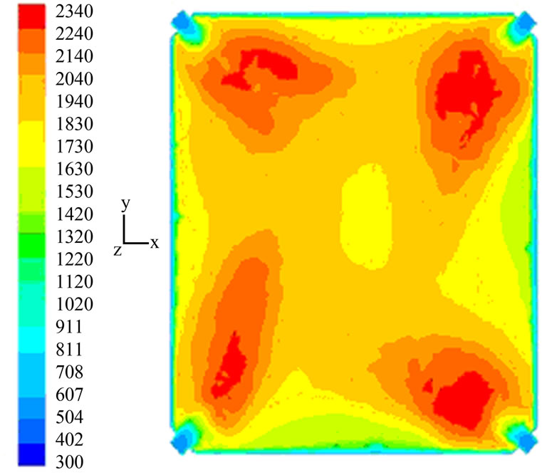
Figure 3. The fluid flow pattern colored by the fluid temperature.
transfer coefficient inside the short tubes would be also greater in compare with the medium and long tubes. It means that the quantity of heat transfer from the crust of such tubes into the hot vapor inside them would be augmented. This inevitably causes the temperature of the crust of such tubes to be lessened in the extremely hot environment of the boilers’ inner surface. Comparing with the long length tubes, the same results can be concluded with slighter intensity in support of the tubes with medium length, as well. Now, with regard to the results of numerical analysis and their comparison with the design temperature reported by the reference (Isfahan Power plant Documents 2009) [5], the fact has become unambiguous that thermally, the temperature of medium and long tubes in zones such as the knees close to the outlet header would function in temperatures higher than the design temperature. Figure 4 depicts the thermal variations of different types of platen superheater tubes and Figure 5 shows the pressure variations of superheat vapor inside these tubes.
6. Suggested Solutions and the Consequential Results
In this section, the decline of superheater tubes’ crust temperature in certain physical situations and localities has been taken into consideration as one of the important factors in preventing them from being ripped or destroyed. Then the following solutions have been applied:
1) Changing the angle of air channels and the fuel nozzles to the horizon (with notice to type of boiler fuel):
One of the effective contributors in the thermal distribution inside the boilers is the modality of burners’ arrangement or more precisely, the modality of air channels and fuel nozzles’ arrangement. We tried to direct the thermal pyramid resulting from combustion to the floor of the boiler by changing the angle of air channels and fuel nozzles to the surface of horizon. For this solution, the changes of burners’ angle to the floor of the boiler in the suggested area by the manufacturer company (0 to 30 degrees) was proposed. Then, with regard to the two facing paradoxical goals i.e. increasing the temperature of tubes’ outlet vapor from one hand and decreasing the temperature of superheater tubes from the other hand, the optimal angle was predicted. For that reason, the temperature of outlet vapor from the superheater tubes and the temperature of tubes’ surface were compared with the power plant data and the angle which could satisfied both of the objectives, was selected. For this purpose, twelve assumptive pages from the uppermost flat of the burners i.e. a 14 meter height from the floor of the boiler to a 26 meter height from the floor of the boiler which is a one-meter distance from the below of short platen superheater tubes, were presumed.
Then the average temperature was calculated for each of these 12 zones. Consequently, the effectuality of this solution on the quantity of temperature variations inside the boiler and the specified zones was examined by changing the angle of channels and nozzles in each flat of the burner.
Using the thermal radiation shields for the critical zones thermally:
After identifying the critical zones which are prone to the maximization of temperature, local thermal shields were used for this parts of the platen superheater tubes. for a simple description of theoretical analysis on how the application of radiation shields could reduce the heat transfer to critical zones, we should discuss about radiation interchange between combustion products, superheater tubes and water wall tubes.
At first, we consider the chemical reaction governing on the boiler as below:
 (11)
(11)
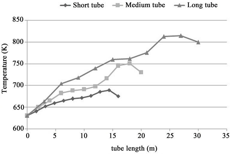
Figure 4. Changes of temperature on superheater tubes without the thermal shields.
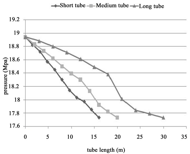
Figure 5. Changes of vapor pressure inside the platen superheater tubes.
where:

In next step, some of parameters are calculated, such as partial pressure of combustion products, Adiabatic flame temperature [10,11] and average path length (Le) of radiance [11,12].
With these data, we could measure emissivity and absorptivity coefficients of combustion products by help from several practical data base table that belong to Hottel and Egbert [11,12]. These parameters have main role for calculation radiation heat transfer from flame or combustion products to superheater tubes, (Please see to Figure 6).
Therefore, Radiation heat transfer to platen superheater tubes by combustion products is equal to:
 (12)
(12)
where A is side area of superheater tube, εg is emissivity coefficient of mixture of combustion products, αg is absorptivity coefficient of mixture of combustion products, σ is Stefan-Boltzmann coefficient, Tg is flame temperature and Tw is superheater wall temperature. Convection heat transfer to platen superheater tubes by combustion products is equal to:
 (13)
(13)
where h is convection coefficient. It is determined by Nusselt equation (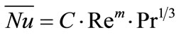 ) that for 40 < Re < 4000, constant factors C and m are 0.688 and 0.466 respectively.
Also velocity of combustion products is calculated by measurement outlet mass flow of stack or GR fan. These data are used for calculation of Reynolds number (Re) and Prantl number (Pr). When radiation thermal shields are applied on critical zones, radiation heat flux toward superheater is reduced by these shields, (Please see to Figure 7).
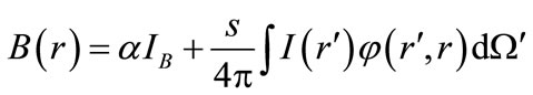
 (14)
(14)

In other words, with application radiation shields, the thermal resistance is increased and in following this state, radiation heat transfer to superheater tubes is reduced. With notice that the main part of heat transfer in the platen superheaters is carried out to radiation form, the radiation thermal shields happened to be effective in moderating the temperature of critical zones. Radiation shields were taken from materials with low emissivity coefficient and high reflectivity or scattering coefficient, such as: steel thermal shields, ceramic thermal shields and thermal shields with FGM cover. In this present research, only steel shields were used. Data of these shields is listed in Table 1.
7. Conclusion
With notice to type of fuel (gas) and reach to the temperature needed for high pressure turbin, also optimum
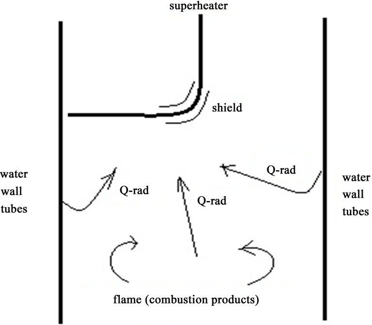
Figure 6. Radiation heat transfer toward the superheater.
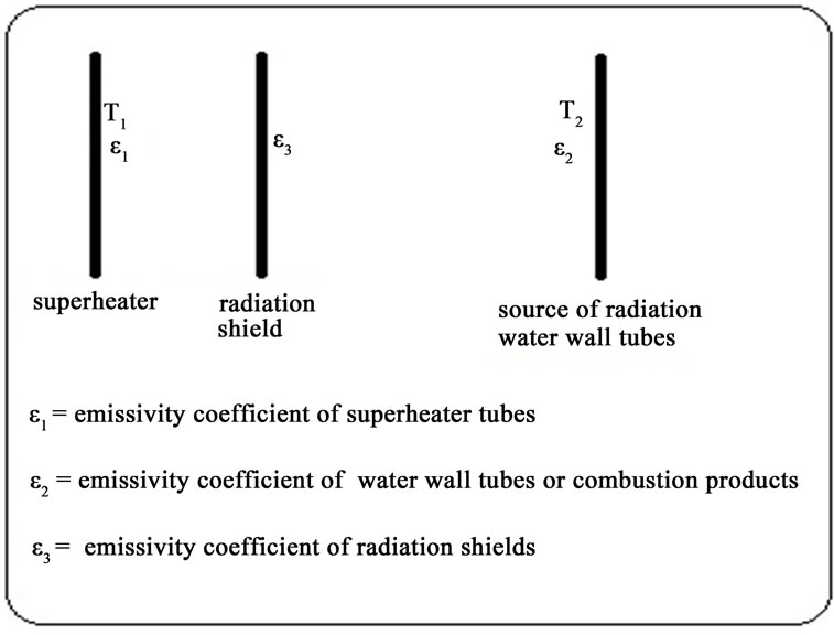
Figure 7. Radiation shield between superheater and source.
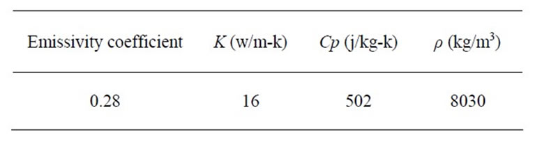
Table 1. Properties of thermal shield.
angles (5 to 10 degree) were predicted in between the angles that were offered by boiler composer factory (–30 to 30 degree). the heat pyramid was well decreased with change in burner’s angle toward the boiler floor (Please see to Figure 8). After the application of a set of thermal radiation shields with low emissivity coefficient and high reflectivity or scattering coefficient on the knees of long and medium tubes of platen superheater, and with comparing the temperature of three rows of the superheater tubes before and after using the thermal radiation shields, the effect of these shields is well known for the decrease of temperature in the critical bends (Please see to Figure 9). Please note that thermal radiation shields were used only on final bends of medium and long tubes. The results of this modeling are presented with Table 2 and Table 3 and then compare with other references or power plant’s data.
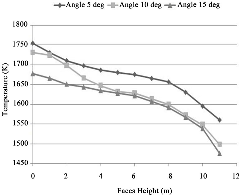
Figure 8. Changes of temperature pyramid with change of burners angles.
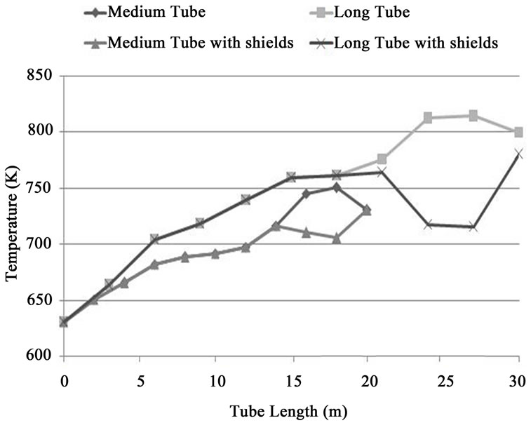
Figure 9. Changes of temperature on platen superheater tubes with & without thermal shields.
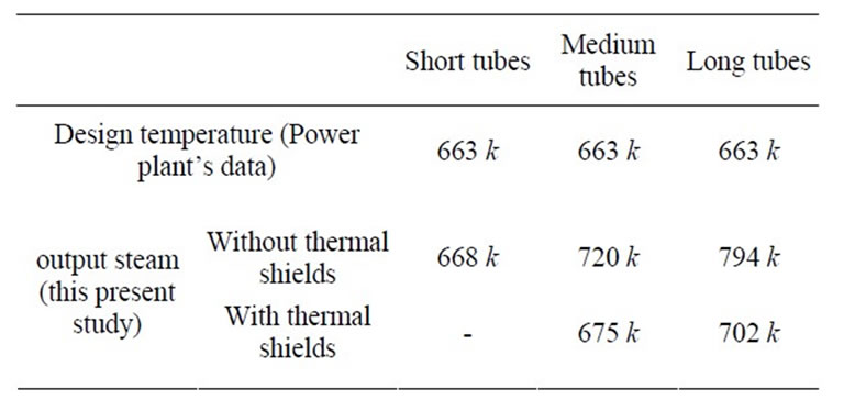
Table 2. Comparing the temperature of output steam resulting from this investigation.

Table 3. Comparing the temperature of tubes crust resulting from this investigation with other papers.
8. Acknowledgements
The authors of this paper would like to thank from managements of the Isfahan power station, city of Isfahan, Iran, for providing the boiler maps and documents.
REFERENCES
- M. Manickam and M. P. Schwarz, “CFD Modeling of Waste Heat Recovery Boiler,” Applied Mathematical Modeling, Vol. 22, No. 10, 1998, pp. 823-840. doi:10.1016/S0307-904X(98)10020-3
- M. Abdullin and V. Vafin, “Numerical Investigation of the Effect of a Tube Water-Wall and Combustion Products on Heat Transfer in Tube Furnaces,” Journal of Engineering Thermophysics, Vol. 65, No. 2, 1994, pp. 752-757.
- M. Rahimi, A. Khoshhal and S. M. Shariati, “CFD Modeling of a Boiler Tubes Rupture,” Applied Thermal Engineering, Vol. 26, No. 17-18, 2006, pp. 2192-2200. doi:10.1016/j.applthermaleng.2006.03.017
- M. Xu, J. L. Azevedo and M. G. Carvalho, “Modeling of the Combustion Process and NOx Emission in a Utility Boiler,” Fuel, Vol. 79, No. 13, 2000, pp. 1611-1619. doi:10.1016/S0016-2361(00)00019-3
- T. Esfahan, “Boiler Pressure Parts Data Sheets—Isfahan Power Plant’s Documents,” 2009, (Unpublished).
- S. H. Tufail and S. H. Pso, “Failure of Superheater of Boiler Tubes,” Corrosion Science and Engineering, Vol. 6, No. C100, 2005, pp. 100-106.
- H. K. Versteeg and W. Malalasekera, “An Introduction to Computational Fluid Dynamics,” Longman Ltd., London, 1995.
- D. B. Spalding, “Chemical Reaction in Steady Confined Turbulent Flame,” Symposium (International) on Combustion, Vol. 13, No. 1, 1976, pp. 649-657. doi:10.1016/S0082-0784(71)80067-X
- B. F. Magnussen and B. H. Hjertager, “On Mathematical Models of Turbulent Combustion with Special Emphasis on Soot Formation and Combustion,” Symposium (International) on Combustion, Vol. 16, No. 1, 1976, pp. 719-729. doi:10.1016/S0082-0784(77)80366-4
- F. P. Incropera, D. P. DeWitt, et al., “Introduction to Heat Transfer”, 5th Edition, Wiley, Hoboken, 2007.
- F. P. Incropera, D. P. DeWitt, et al., “Fundamentals of Heat and Mass Transfer,” 6th Edition, Wiley, Hoboken, 2007.
- J. C. Tannehill, D. A. Anderson and R. H. Pletcher, “Computational Fluid Mechanics and Heat Transfer,” Taylor & Francis Group, 1997.
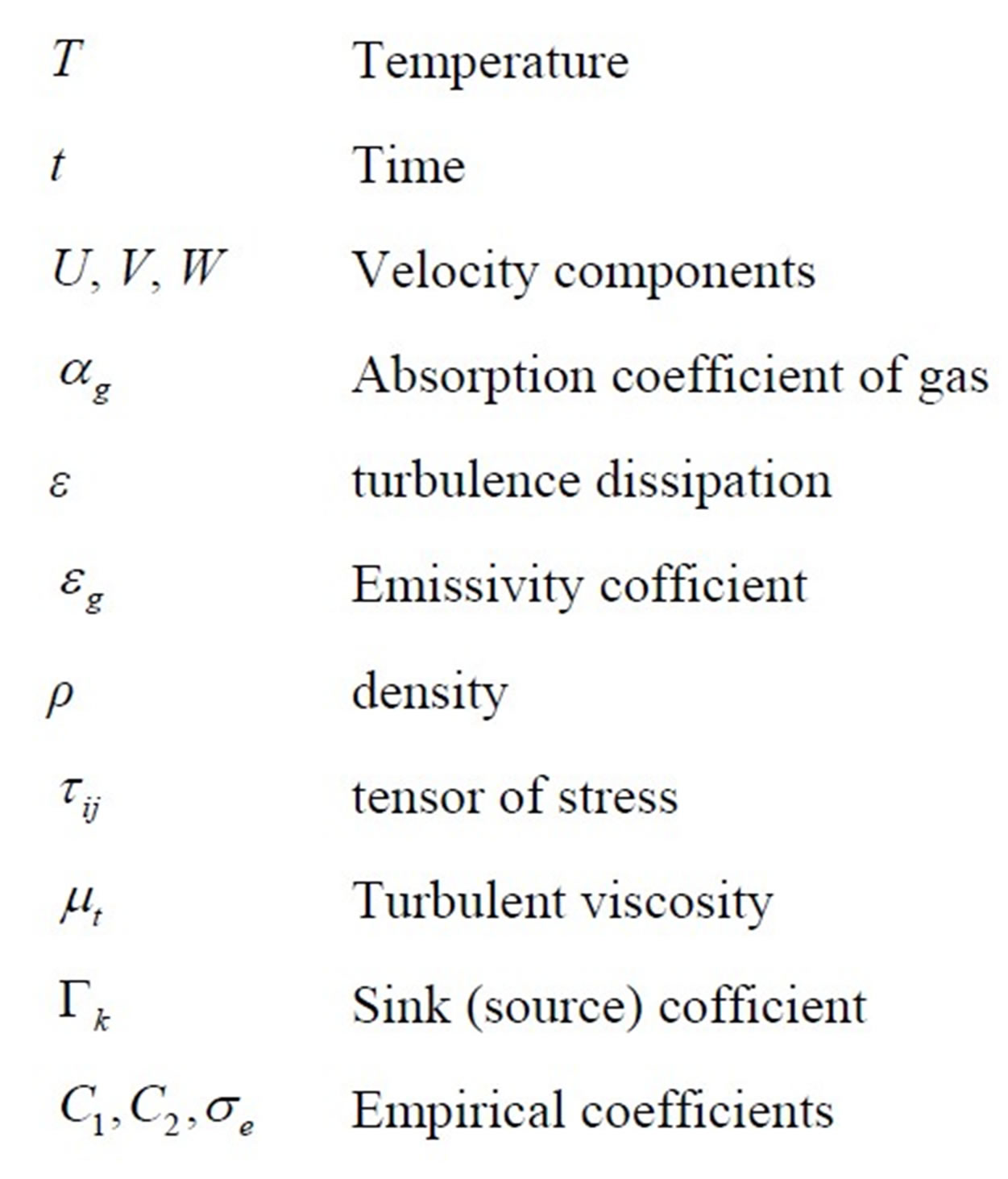
Nomenclature