World Journal of Mechanics
Vol.4 No.7(2014), Article
ID:48295,9
pages
DOI:10.4236/wjm.2014.47024
The Ratcheting Behaviour of Plain Carbon Steel Pressurized Piping Elbows Subjected to Simulated Seismic In-Plane Bending
S. J. Zakavi*, M. Ajri, V. Golshan
Department of Mechanical Engineering, University of Mohaghegh Ardabili, Ardabil, Iran
Email: *zakavi@uma.ac.ir
Copyright © 2014 by authors and Scientific Research Publishing Inc.
This work is licensed under the Creative Commons Attribution International License (CC BY).
http://creativecommons.org/licenses/by/4.0/


Received 9 May 2014; revised 4 June 2014; accepted 28 June 2014
ABSTRACT
In this paper, cyclic loading behavior of carbon steel pressurized piping elbows are described. Effects of internal pressure and bending moment amplitude on the ratcheting rate are investigated. The AF kinematic hardening model is used to predict the plastic behavior of the elbows. Material parameters and stress-strain data have been obtained from several stabilized cycles of specimens that are subjected to symmetric strain cycles. The results show that the maximum ratcheting strain occurred mainly in the hoop direction at flanks. Hoop strain ratcheting was found at intrados for individual specimen. Ratcheting strain rate increases with increase of the bending loading level at the constant internal pressure. The results show that the initial rate of ratcheting is large and then it decreases with the increasing cycles. The FE model predicts the hoop strain ratcheting rate to be near that found experimentally in all cases that .
.
Keywords:Pressure Pipe, Ratcheting, Carbon Steel, Nonlinear Kinematic Hardening Model, Cyclic Loading

1. Introduction
Piping systems, especially elbows are an important part of power plants components. When this components are cyclically loaded in the plastic regime, progressive plastics deformation can occur by a combination of primary (steady) loading and secondary (cyclic) loading. This phenomenon is called as ratcheting and the accumulated plastic strain produced during above-mentioned cyclic deformation is called as ratcheting strain. The ratcheting is a phenomenon for the asymmetrical stress-controlled cycling and is important in designing above-mentioned structural components. Various models have been proposed for simulating cyclic and time independent behavior of materials such as Prager [1] , Armstrong and Frederick [2] , Ohno and Wang [3] , Chaboche [4] -[6] plasticity models. Many efforts have been made to understand the ratcheting phenomena. Chen et al. [7] -[9] experimentally studied multiaxial ratcheting for pressurized low carbon steel elbows under reversed bending. It was shown that the maximum ratcheting strain occurred mainly in the hoop direction at flanks. Tasnim, et al. [10] -[12] simulated the plastic behavior of CS1026 and CS1020 carbon steels at cyclic loading. Zakavi et al. [13] studied the ratcheting behavior of the pressurized carbon steel (BS4360-43A) and stainless steel (304 L) straight pipe subjected to the seismic bending moment with the nonlinear combined hardening model using finite element code, ABAQUS. The finite element results were compared with those obtained from the experiments to evaluate the capability of the proposed AF model with isotropic/kinematic hardening rule to predict the cyclic loading behavior of the straight pipe. The results showed that the hoop-ratcheting strain predicted by FE analysis to be close to that found experimentally in all cases with M = MP0:2 ≤ 1. Otherwise, FE analysis gave overestimated values compared with the experimental data. The influences of mean stress and stress amplitude on ratcheting were evaluated using stress-controlled tests. Bari and Hassan [14] -[16] studied several kinematic hardening models for ratcheting prediction on steels. Koo and Lee [17] studied cyclic softening of the modified 9Cr-Mo steel at elevated temperatures. They showed that the cyclic softening behavior of the modified 9Cr-1Mo steel can invoke a ratcheting instability when the applied cyclic loads exceed a certain level of the ratchet loading condition. In this paper a finite element analysis with the nonlinear kinematic hardening model is used to evaluate ratcheting behavior of pressurized elbow subjected to dynamic bending moment. The results of this model are discussed for structures under various types of cyclic loads in references (Rahman, et al. [18] ; Eslami, et al. [19] ; Prager, [1] ).
2. Materials and Methods
In this paper, a finite element code, ABAQUS, is used to study the ratcheting of carbon steel pressurized elbow subjected to cyclic bending loading. In the experimental tests [20] , series of tests have been undertaken subjecting pressurized elbow specimens to rising amplitude dynamic (5 Hz, the resonant frequency) bending moments. Then, by conducting a series of finite element runs based on the nonlinear kinematic hardening model using the ABAQUS, the experimental tests are modeled and ratcheting data obtained. Then the two sets of results are compared with each other.
3. Nonlinear Kinematic Hardening Models
The kinematic hardening models are used to simulate the inelastic behavior of materials that are subjected to cyclic loading. The use of plasticity material models with isotropic type hardening is generally not recommended since they continue to harden during cyclic loading. The isotropic hardening model always predicts shakedown behavior, if creep is not considered [21] . The kinematic hardening plasticity models are proposed to model the inelastic behavior of materials that are subjected to repeated loading. For example, the ArmstrongFrederick [2] kinematic hardening model is suggested for the nonlinear strain hardening materials. Based on the Armstrong-Frederick nonlinear kinematic hardening rule, many constitutive models have been constructed to simulate the unaxial and multiaxial ratcheting of materials characterized by cyclic hardening or cyclic stable behaviors. The results of these models are discussed for structures under various types of cyclic loads in references.
The classical linear kinematic hardening rule and different nonlinear kinematic hardening models are available for the plastic analysis of structures. The nonlinear kinematic hardening model was first proposed by Armstrong and Frederick [2] . Nonlinearities are given as a recall term in the Prager rule. So that the transformation of yield surface in the stress space is different during loading and unloading. This is done by assuming different hardening modulus in loading and unloading conditions. The yield function for time independent plasticity, using the von-Mises yield criterion, is expressed as [22] :
 (1)
(1)
where ![]() is the back stress tensor,
is the back stress tensor,  the initial size of the yield surface, and denotes the von-Mises distance in the deviatoric stress space:
 (2)
(2)
where ![]() and
and ![]() are the stress and back stress tensors, and
are the stress and back stress tensors, and  and
and  are the stress and back stress deviatoric tensors in the stress space, respectively. The nonlinearities are given as a recall term in the Prager rule:
 (3)
(3)
where  is the equivalent plastic strain rate,
 ![]() and
and  are two material dependent coefficients in the Armstrong–Frederick kinematic hardening model, and
  stands for the linear kinematic rule. The normality hypothesis and the consistency condition
  lead to the expression for the plastic strain rate [22] :
 (4)
(4)
where ![]() denotes the Heaviside step function:
denotes the Heaviside step function:  if
if ,
,  if
if  and the symbol
  denotes the MacCauley bracket, i.e.,
 . The hardening modulus
  becomes:
 (5)
(5)
In the case of tension-compression, the criterion and the equations of flow and hardening can be expressed in the form (Lemaitre and Chaboche, [22] ):
 (6)
(6)
 (7)
(7)
 (8)
(8)
 (9)
(9)
The evolution equation of hardening can be integrated analytically to give:
 (10)
(10)
where  according to the direction of flow, and
  and
and  are the initial values, for example, at the beginning of each plastic flow.
4. Review of Experimental Set-up [20]
The experimental set-up for testing piping elbows under in-plane bending has been reported in reference [20] . The nominal pipe size was 2 inch NPS corresponding to an outside diameter of 60.3 mm. The component identification and relevant dimensions of the elbows are given in Table1 For carbon steel (ASTM A106B) material

Table 1. Component identification and geometry (Carbon steel) [20] .
*Components are labelled by a four-character coding: First character: C for carbon; Second character: L for long or S for short radius bends; Third character: S for standard weight or X for extra strong; Fourth character: I is used here to denote in-plane bending to differentiate from another programme concerned with out-of-plane 0 loading.
specification and properties obtained by tensile tests data is given in Table2 The parameters and section of the experimental results is shown in Figure 1. Pairs of 90˚ welding elbows [20] have, for symmetry, been tested simultaneously. The loading was applied in two stages. First, the test components were pressurized independently to their design pressure, calculated using the ASME Code formula. The internal pressure kept constant during testing. Next, the dynamic load to induce the cyclic bending was applied at the end nodes of the simulation model. It was specified as a sinusoidal force with a circular frequency. The frequency and design pressure of elbows is given in Table3 Hoop strains at the crown reading from the gauges attached to the elbows at the crown positions (Figure 1).
5. Finite Element Arrangement
For all specimens the finite element code, ABAQUS, was used to study ratcheting behavior of pressurized elbows under simulated seismic bending moments. The elbows have a 1.50 m long pipework modeled by 28 elements. The most accurate element in the ABAQUS code for this type of structural system considering beam
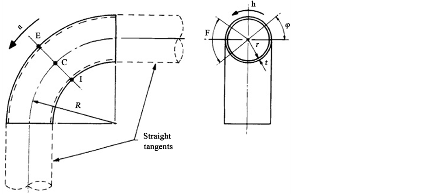
Figure 1. Elbow geometry, stress directions, angular coordinate and definition of important locations around the bend [20] ). a = axial direction; h = hoop direction; ϕ = angular position around mid-circumference section containing E, C and I = 0˚ at C and positive towards E; C = crown positions (ϕ = 0˚, 180˚); E = extrados (ϕ = +90˚); F = flank regions (defined by ϕ = ±45˚ about the crowns); I = intrados (ϕ = −90˚).
Table 2. Material (Carbon steel) properties obtained by tensile tests.
Table 3. The frequency and design pressure.
elements, pipe elements and elbow elements is the elbow element. Four types of elbow elements are available in the ABAQUS library, of which the two-noded element ELBOW31 was found to give the best results. ELBOW31 provides accurate predictions of the behavior of elbows under monotonic loading. In this paper, in order to predict the results, the tensile specimens were produced accordance with the materials properties that is given in Table2
The cyclic nonlinear constitutive model used in the FEM analyses in this study is derived from multiaxial formulations by Armstrong and Frederick. It is recommended that the model be calibrated with experimental data that is close to the expected strain range and loading history of the application. Stress-strain data is obtained from several stabilized cycles of specimens that are subjected to symmetric strain cycles. The material parameters ![]() and
and  determine the kinematic hardening component of the model. Three different ways of providing data for the kinematic hardening component of the mode can be given: using half-cycle test data, using single stabilized cycle, or test data obtained from several stabilized cycles. Stress-strain data can be obtained from several stabilized cycles of specimens that are subjected to symmetric strain cycles.
The calibration procedure consists of several cylindrical bar tests, one of which subjected to monotonic tension until necking and others were under symmetric strain-controlled experiments with different strains. During these calibration tests, the stress state must remain uniaxial.
From symmetric strain-controlled experiments, the equivalent plastic strain equals the summation of the absolute value of the change in longitudinal plastic strains:
 (11)
(11)
where  total strain,
  is the measured stress and E is the elastic modulus.
The equivalent back stress,  , equals one-half of the difference in yield stress between the end of the tensile loading and first yield of the subsequent compressive loading.
These results, corresponding  data pairs may be plotted, and the kinematic hardening parameters,
 ![]() and
and , may be calculated by fitting Equation (10) to the data and selecting parameters minimize the sum of the square of the error between Equation (10) and the data.
For symmetric strain-controlled experiments, a typical curve with strain amplitude ±0.75 is shown in Figure 2. The results gained experimentally and from FE using nonlinear kinematic hardening model with C = 2763.69 Mpa,  are detailed below.
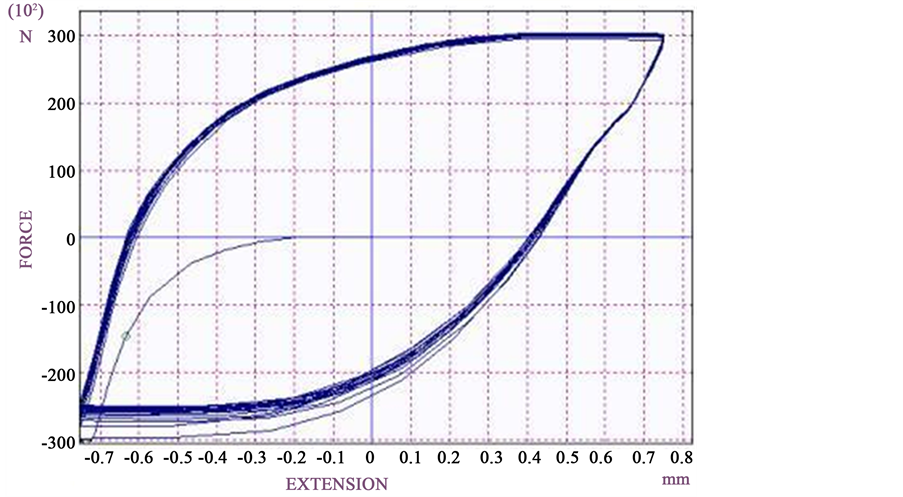
Figure 2. Typical cyclic loading curve with strain amplitude ±0.75 for carbon steel.
6. Experimental and FE Results
Detailed results will be presented for four of the specimens tested (CLSI, CLXI, CSSI and CSXI) and summary results will be given for all tests conducted. Typical strain response in presence of ratcheting in FE results are shown in Figure 3.
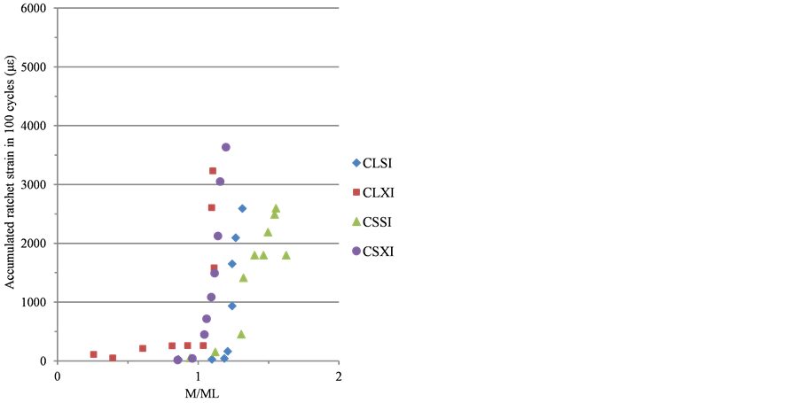
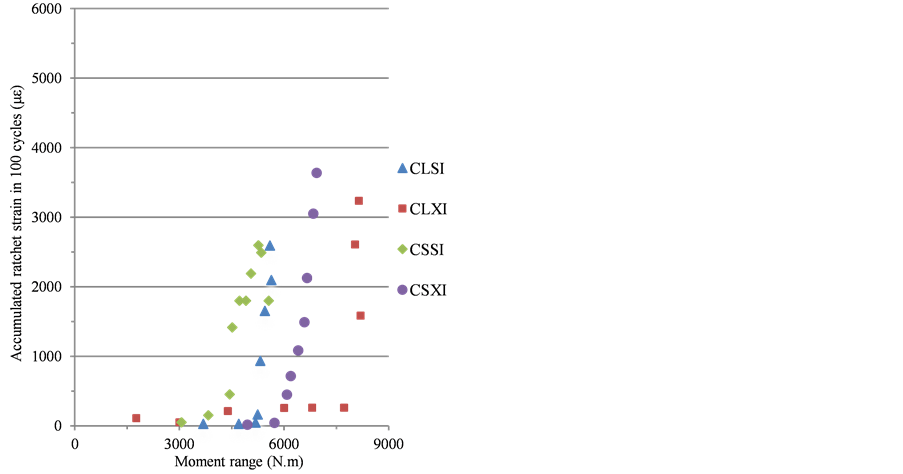
All of the experimental ratcheting results from the tests and from FE analysis on specimens CSSI, CLSI, CLXI and CSXI are plotted in Figure 4 and Figure 5. Here, the strain for each cycle has been calculated as the average over the period of the test and plotted against M/M0.2. Figure 4 and Figure 5 show the data recorded for the crown surface.
The response of the specimens during these tests is illustrated in Figure 5(a). The dynamic bending moment experienced by the specimen has been plotted against the input displacement for each of the specimens CLSI, CLXI, CSSI and CSXI. In Table 4, the ratchet strains found experimentally over the test period and by FE
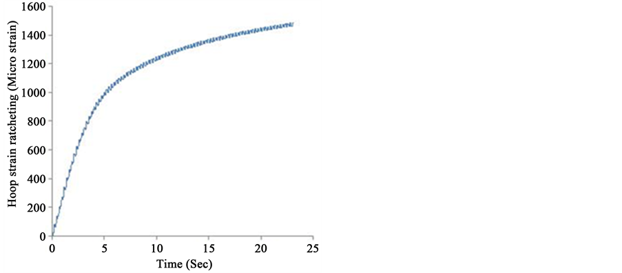
Figure 3. Typical strain response in presence of ratcheting in FE results for specimen CSXI at a dynamic bending moment of 6136.
 (a)
(a)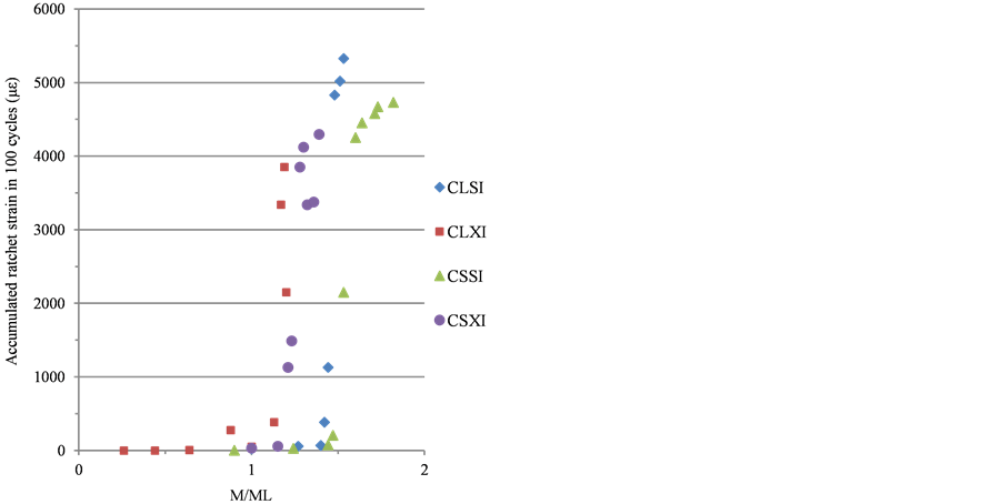 (b)
(b)
Figure 4. (a) Experimental ratcheting data [20] and (b) FE analysis against moment levels for carbon steel.
Table 4. Experimental and FE ratcheting data for specimen CSXI.
 (a)
(a) (b)
(b)
Figure 5. (a) Experimental ratcheting data [20] and (b) FE analysis against moment levels for carbon steel.
analysis, for the same period, for specimen CSXI are summarized.
7. Results and Discussion
Results on four pairs of carbon, long and short radius piping elbows with two different thicknesses have been presented. The components were subjected to steady internal pressure and resonant, dynamic in-plane bending moments. The cyclic strain accumulation as a function of geometry and load level was assessed for all components. This paper, reviews the experimental observations and the FEA results of the structural ratcheting. Experimental and simulation results show that cyclic bending of elbows induces cyclic strain accumulation. Ratcheting has been found to be greater in the crown hoop direction than in the axial direction in all specimens, and increased rapidly once initiated. Ratcheting strains mainly occur in the circumferential direction. Such responses are imperative for understanding the ratcheting-fatigue failure mechanisms, and developing and validating simulation models for tubular structures. Despite that there are considerable advancements in cyclic plasticity models, they are still not robust enough to simulate the structural response when model parameters are determined from material response only.
Typical data obtained experimentally and from FE model for specimens CLSI to CSXI on the crown surface are shown in Figure 4 and Figure 5. For the carbon steel elbows, the onset of ratcheting did not start until moment levels of about M/Ml = 1. Complete set of data for specimens CSXI is presented in Table4
8. Conclusion
The important conclusion of this paper is to show the properties of nonlinear kinematic hardening model to predict the cyclic loading behavior of the structures. In this study, stress-strain data and material parameters have been obtained from several stabilized cycles of specimens that are subjected to symmetric strain cycles. Both experimental results and the FE analysis agree that ratcheting is influenced by the material stress-strain curve and load history. The rate of ratcheting depends significantly on the magnitude of the internal pressure, dynamic bending moment and material constants for nonlinear kinematic hardening model. The results show that the initial rate of ratcheting is large and then it decreases with the increasing cycles. The FE model predicts the hoop strain ratcheting rate to be near that found experimentally in all cases that . The ratcheting strains were found to be in general higher for the high thickness than for the low thickness elbows.
Acknowledgements
Late Appreciation is expressed to the technical staff of the Applied Mechanics Division of the Department of Mechanical Engineering at the University of Mohaghegh Ardabili (Iran) for their assistance with the work.
References
- Prager, W. (1956) A New Method of Analyzing Stresses and Strains in Work-Hardening Plastic Solids. Journal of Applied Mechanics, 23, 493-496.
- Armstrong, P.J. and Frederick, C.O. (2007) A Mathematical Representation of the Multi Axial Bauschinger Effect. Materials at High Temperatures, 24, 1-26.
- Ohno, N. and Wang, J.D. (1993) Kinematic Hardening Rules with Critical State of Dynamic Recovery, Part I: Formulations and Basic Features for Racheting Behavior. International Journal of Plasticity, 9, 375-390. http://dx.doi.org/10.1016/0749-6419(93)90042-O
- Chaboche, J.L. (1986) Time-Independent Constitutive Theories for Cyclic Plasticity. International Journal of Plasticity, 2, 149-188. http://dx.doi.org/10.1016/0749-6419(86)90010-0
- Chaboche, J.L. (1991) On Some Modifications of Kinematic Hardening to Improve the Description of Ratchetting Effects. International Journal of Plasticity, 7, 661-678. http://dx.doi.org/10.1016/0749-6419(91)90050-9
- Chaboche, J.L. (2008) A Review of Some Plasticity and Viscoplasticity Constitutive Theories. International Journal of Plasticity, 24, 1642-1963. http://dx.doi.org/10.1016/j.ijplas.2008.03.009
- Chen, X., Gao, B. and Chen, G. (2005) Multiaxial Ratcheting of Pressurized Elbows Subjected to Reversed In-Plane Bending. Journal of Pressure Equipment and Systems, 3, 38-44.
- Chen, X., Gao, B. and Chen, G. (2006) Ratcheting Study of Pressurized Elbows Subjected to Reversed In-Plane Bending. Journal of Pressure Vessel Technology, 128, 525-532. http://dx.doi.org/10.1115/1.2349562
- Chen, X.H., Chen, X., Yu, D.J. and Gao, B.J. (2013) Recent Progresses in Experimental Investigation and Finite Element Analysis of Ratcheting in Pressurized Piping. International Journal of Pressure Vessels and Piping, 101, 113-142. http://dx.doi.org/10.1016/j.ijpvp.2012.10.008
- Tasnim, H. and Kyriakides, S. (1992) Ratcheting in Cyclic Plasticity, Part I: Uniaxial Behavior. International Journal of Plasticity, 8, 91-116. http://dx.doi.org/10.1016/0749-6419(92)90040-J
- Tasnim, H., Corona, E. and Kyriakides, S. (1992) Ratcheting in Cyclic Plasticity, Part II: Multiaxial Behavior. International Journal of Plasticity, 8, 117-146. http://dx.doi.org/10.1016/0749-6419(92)90010-A
- Tasnim, H., Lakhdar, T. and Shree, K. (2008) Influence of Non-Proportional Loading on Ratcheting Responses and Simulations by Two Recent Cyclic Plasticity Models. International Journal of Plasticity, 24, 1863-1889.
- Zakavi, S.J., Zehsaz, M. and Eslami, M.R. (2010) The Ratchetting Behavior of Pressurized Plain Pipework Subjected to Cyclic Bending Moment with the Combined Hardening Model. Nuclear Engineering and Design, 240, 726-737. http://dx.doi.org/10.1016/j.nucengdes.2009.12.012
- Bari, S. and Hassan, T. (2000) Anatomy of Coupled Constitutive Models for Ratcheting Simulation. International Journal of Plasticity, 16, 381-409. http://dx.doi.org/10.1016/S0749-6419(99)00059-5
- Bari, S. and Hassan, T. (2001) Kinematic Hardening Rules in Uncoupled Modeling for Multiaxial Ratcheting Simulation. International Journal of Plasticity, 17, 885-905. http://dx.doi.org/10.1016/S0749-6419(00)00031-0
- Bari, S. and Hassan, T. (2002) An Advancement in Cyclic Plasticity Modeling for Multiaxial Ratcheting Simulation. International Journal of Plasticity, 18, 873-894. http://dx.doi.org/10.1016/S0749-6419(01)00012-2
- Koo, G.H. and Lee, J.H. (2007) Inelastic Constitutive Models for the Simulation of a Cyclic Softening Behavior of Modified 9Cr-1Mo Steel at Elevated Temperatures. Journal of Mechanical Science and Technology, 21, 699-707. http://dx.doi.org/10.1007/BF02916348
- Rahman, S.M., Hassan, T. and Corona, E. (2008) Evaluation of Cyclic Plasticity Models in Ratcheting Simulation of Straight Pipes under Cyclic Bending and Steady Internal Pressure. International Journal of Plasticity, 24, 1756-1791. http://dx.doi.org/10.1016/j.ijplas.2008.02.010
- Eslami, M.R. and Mahbadi, H. (2001) Cyclic Loading of Thermal Stress. Journal of Thermal Stress, 24, 577-603. http://dx.doi.org/10.1080/014957301300158111
- Yahiaoui, K., Moffat, D.G. and Moreton, D.N. (1996) Response and Cyclic Strain Accumulation of Pressurized Piping Elbows under Dynamic in Plane Bending. Journal of Strain Analysis for Engineering, 31, 135-151.
- Mahbadi, H. and Eslami, M.R. (2006) Cyclic Loading of Thick Vessels Based on the Prager and Armstrong-Frederick Kinematic Hardening Models. International Journal of Pressure Vessels and Piping, 83, 409-419. http://dx.doi.org/10.1016/j.ijpvp.2006.02.031
- Lemaitre, J. and Chaboche, J.L. (1994) Mechanics of Solid Materials. Cambridge University Press, Cambridge, 584 p.
Notation
![]() Pipe Thickness
Pipe Thickness
 Pipe mean radius
![]() Young’s modulus
Young’s modulus
![]() Applied dynamic moment
Applied dynamic moment
 Yield strength
 Elbow limit moment under out-of-plane bending
 Allowable design stress intensity
 Ultimate strength
 Yield strength
 Bend characteristic = tR/r2
![]() Back stress tensor
Back stress tensor
 Back stress deviatoric tensor
 Initial size of the yield surface
 Materials constants for kinematic hardening
 Plastic strain tensor
 Equivalent plastic strain
 Angular position around the circumference of the bend ( = 0˚ at the crown)
 Test natural frequency
NOTES
![]()
*Corresponding author.