International Journal of Medical Physics, Clinical Engineering and Radiation Oncology
Vol. 1 No. 2 (2012) , Article ID: 21704 , 10 pages DOI:10.4236/ijmpcero.2012.12006
A Laplacian Surface Deformation and Optimization Based 3D Registration Algorithm for Image Guided Prostate Radiotherapy
1Department of Radiation Oncology, Flushing Radiation Oncology, New York, USA
2Department of Computer Science, Rutgers, The State University of New Jersey, Piscataway, USA
3Department of Radiation Oncology, UMDNJ-Robert Wood Johnson Medical School, New Brunswick, USA
Email: yuenj@umdnj.edu
Received May 17, 2012; revised June 22, 2012; accepted July 19, 2012
Keywords: Laplacian Surface Deformation; Laplacian Surface Optimization; 3D Deformable Registration; Prostate
ABSTRACT
Purpose: To develop a fast landmark-based deformable registration method to capture the soft tissue transformation between the planning 3D CT images and treatment 3D cone-beam CT (CBCT) images for the adaptive external beam radiotherapy (EBRT). Method and Materials: The developed method was based on a global-to-local landmark-based deformable registration algorithm. The landmarks were first acquired by applying a fast segmentation method using the active shape model. The global registration method was applied to establish a registration framework. The Laplacian surface deformation (LSD) and Laplacian surface optimization (LSO) method were then employed for local deformation and remeshing respectively to reach an optimal registration solution. In LSD, the deformed mesh is generated by minimizing the quadratic energy to keep the shape and to move control points to the target position. In LSO, a mesh is reconstructed by minimizing the quadratic energy to smooth the object by minimizing the difference while keeping the landmarks unchanged. The method was applied on 8 EBRT prostate datasets. The distance and volume based estimators were used to evaluate the results. The target volumes delineated by physicians were used as gold standards in the evaluation. Results: The entire segmentation and registration processing time was within 1 minute for all the datasets. The mean distance estimators ranged from 0.43 mm to 2.23 mm for the corresponding model points between the treatment CBCT images and the registered planning images. The mean overlap ratio ranged from 85.5% to 93.2% of the prostate volumes after registration. These results demonstrated reasonably good agreement between the developed method and the gold standards. Conclusions: A novel and fast landmark-based deformable registration method is developed to capture the soft tissue transformation between the planning and treatment images for prostate target volumes. The results show that with the method the image registration and transformation can be completed within one minute and has the potential to be applied to real-time adaptive radiotherapy.
1. Introduction
This Prostate cancer is the most commonly diagnosed cancer in men in the United States and is the second leading cause of cancer related deaths in males [1]. The external beam radiotherapy (EBRT) is one of the primary treatment modalities for prostate cancer and can be used to deliver conformal and precise radiation doses to the target volume of prostate while sparing adjacent critical normal organs. Intensity modulated radiation therapy (IMRT), one of the clinical radiation delivery technologies, is being increasingly used in the definitive treatment of prostate cancer compared to the three dimensional conformal radiotherapy (3DCRT). The beam intensity is modulated and optimized with sophisticated algorithms not only to produce more conformal dose coverage to the target volume but also to further reduce radiation doses to the surrounding critical structures. However, the organ motions and patient positioning deviations during treatment impose challenges in the EBRT and may compromise the efficacy of these advanced radiation delivery technologies [2-5].
Image guided radiotherapy (IGRT) has been developed to improve the detection of target deviations relative to the target position in an approved radiotherapy treatment plan [6]. When using IGRT, verification images may be acquired at the treatment and compared to the planning images, and the deviations can be detected and corrected. The combination of advanced imaging tools with the state of the art radiation delivery technologies may potentially improve both cancer control and quality of life for cancer patients. The success of this combination hinges on the following prerequisite: precise and fast delineation and registration of the target volume between the planning and the verification images. This is because not only planned dose needs to be delivered to the correct target volume but also the process of target localization at treatment cannot be prolonged to an unacceptable level to compromise patient comfort and treatment time.
Various imaging based rigid registration methods have been developed to automate the process of determining patient positioning [7-12]. These methods have been aimed at registering 3D CT data to 2D portal images. The significant downfall of these methods is that only rigid pelvic bony landmarks are used while the location of prostate itself is not considered. In one study [13], deformable soft tissues were evaluated using an automated CT-CT image registration method; however, that work only considered translations alone. Rigid registration can be an acceptable approach to a number of medical applications. However, the detection of target deviations in radiation treatment of prostate cancers is an area where the rigid registration alone is most likely not to be successful because the dense registration and correspondence problems are involved and need to be solved.
Various full 3D deformable registration methods have been developed to register images in the prostate region, such as biomechanical models, conformal mapping, thin plate spline, diffusion based models, and free form deformation [14-26].
Biomechanical models can be time consuming since the mechanical information of the tissue is required to perform the deformation [14-16]. Conformal mapping method is applied to map bladder deformations and difficulties can be encountered to model the interfaces between structures [17]. Thin plate spline (TPS) approach formulates landmark based image registration as a nonrigid point matching system [18-20]. The main concern related to this approach is the automatic finding of landmark correspondences. In diffusion based “demons” deformation method, images are processed to be a set of isointensity contours and the source image diffuses into the target image [21,22]. The free form deformation registration method is to deform the shape of an object by manipulating a regular control lattice overlaid on its volumetric embedding space [23-26].
In one of our previous studies [26], a global-to-local shape registration model was developed to formulate shape based non-rigid registration in a hierarchical manner: first, the mutual information criterion supporting the transformation models was optimized to perform global registration; then the information of the segmented volume was implicitly used by fitting deformable superquadric mesh models and the Euclidian distances of the corresponding nodal points from the global registration process were minimized in the local registration process. However, in the first step of global deformation, maximizing mutual information can be time consuming and make the approach impractical in a clinical treatment environment. In the second step of this previous approach, the use of deformable superquadric mesh models of local deformation can be limited and become ineffective in cases where deformation becomes excessive or the target shapes are irregular beyond certain limits.
To overcome the limitations of the previous method, we developed a new global-to-local deformable registration method which incorporated both computationally efficient landmark points based global registration method and a new computationally efficient local deformable mesh model based local registration algorithm.
2. Materials and Methods
In the global registration, the corresponding landmark points were first acquired by applying the anatomy-constrained robust active shape models (ACRASM) segmentation method [26]. Then, the corresponding landmark points based global registration method was applied. The speed of this global registration method was 50 - 70 times faster than that of volume based mutual information method.
In the local registration, the Laplacian surface deformation (LSD) [27] method was employed for local deformation and Laplacian surface optimization (LSO) [28] method was employed for refining mesh model to reach an optimal registration solution.
The flow chart of the segmentation and registration process is shown in Figure 1.
2.1. Patient Data
Eight different patients undergoing external beam prostate
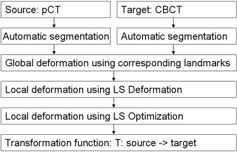
Figure 1. The flow chart of the segmentation and registration method of the prostate.
radiotherapy were randomly selected for the study and evaluations. Each of the patients had one set of planning CT images and one set of CBCT images. The planning CT (pCT) images were acquired with an AcQSim CT scanner (Philips Medical Systems, Andover, MA). The number of slices was different for different patients, ranging from 85 slices to 121 slices. Image slice was 512 × 512 pixels with a voxel dimension of 0.94 × 0.94 × 3 mm3. The treatment CBCT images were acquired by an On-Board Imager (OBI, Varian Medical Systems). The number of slices was also different for different patients, ranging from 55 slices to 61 slices. Each slice had 512 × 512 pixels with a voxel dimension of 0.3 × 0.3 × 2.5 mm3.
The target volumes in pCT images were contoured for treatment planning purposes on an Eclipse treatment planning system (Varian Medical Systems, CA) by an experienced radiation oncologist specializing in prostate cancer management. The target volumes were also manually delineated by the same radiation oncologist on the CBCT images. These manually delineated target volumes from the CBCT images were used as the benchmarks for comparison and evaluation. All the contours were rviewed and confirmed by another radiation oncologist.
2.2. Image Preprocessing
2.2.1. Mage Resampling and Image Contrast Enhancement
Since the pCT and CBCT image slice had different voxel dimensions and different field-of-view size, all the image datasets were resampled in both pCT and CBCT to a uniform voxel dimension 0.3 × 0.3 × 0.3 mm3. After the resampling process, the pCT and CBCT will have same voxel dimensions and similar field-of-view size.
The image intensity was first normalized to [0,1] and the histogram equalization method was applied to enhance the contrast of images in the pCT and CBCT before the image segmentation and deformable registration computation. This image contrast enhancement process helped to improve the accuracies of both the segmentation and the deformable registration.
2.2.2. Rigid Alignment
As a second preprocessing step of the segmentation and deformable registration algorithm, were all automatically aligned in a common reference frame, using a rigid transformation based on the pelvic bony structures. These bony structures normally show less variability compared to soft tissues, and can be automatically identified.
All uniformly resampled image datasets will be first cropped into the volume of interest shown in Figure 2 after rigidly aligned in a common reference frame. The anatomy-constrained robust active shape models (ACRASM) based image segmentation method will be applied on the first cropped volume [26]. The first cropped volumes will be second cropped into the approximate same dimensional volume to largely facilitate the image registration process. The second cropped volumes were generated around the region of interest (include the prostate, seminal vesicles, posterior part of the bladder and anterior part of the rectum). The location and size of the target volume (prostate) and normal organs (bladder and rectum) were used to crop the image volume. For most patients, the cropped volumes will be the same dimensional volume approximately of 150 × 150 × 100 pixels to largely facilitate the image registration process.
 (a)
(a)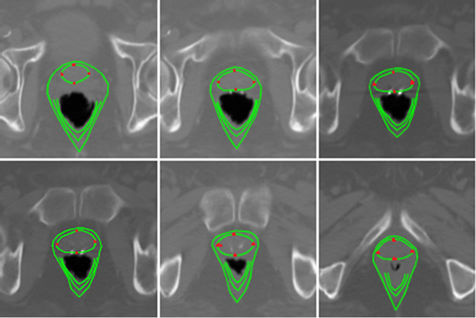 (b)
(b)
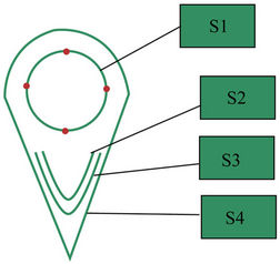
Figure 2. (a) The robust active shape model includes prostate (S1), posterior half internal anal sphincter (S2), posterior half external anal sphincter (S3), the outline borders between the prostate and rectum (S4), in which the anterior border is defined as the anterior part of prostate, the posterior border is defined as the posterior part of iliococoygeus muscle, and the lateral border is defined as the iliococoygeus portion of the levator ani muscle. The four red points on the model S1 is the landmark points. (b) Enhanced planning CT images unfolded from a single 3D planning CT prostate volume and the image segmentation based the anatomy-constrained robust active shape models (ACRASM).
2.3. 3D Automatic Segmentation of Treatment
Planning Images and CBCT Images
The detailed description of the method of segmentation was presented in a previous study [26]. A brief description is presented as follows.
Enhanced planning CT images unfolded from a single 3D planning CT prostate volume were segmented using the anatomy-constrained robust active shape models (ACRASM) [26]. The ACRASM shows in Figure 2(a) includes prostate (model S1), posterior half internal anal sphincter (model S2), posterior half external anal sphincter (model S3), and the outline borders between the prostate and rectum (model S4). The upper, bottom, left and right four points are landmark points of model S1 and the rest points of model S1 are regular points in each image of the 3D planning CT prostate volume. The points in model S2, S3 and S4 are not used in this paper. The landmark points of model S1 in the 3D planning prostate volume will be used in global registration as well as the local registration. Figure 2(b) illustrates the image segmentation of the prostate based the anatomy-constrained robust active shape models and shows model S1 to S4 as well as the four landmark points of model S1.
Enhanced CBCT images unfolded from a single 3D CBCT prostate volume were also segmented using ACRASM method, the same segmentation method by which the enhanced planning CT images were segmented.
The upper, bottom, left and right four points were also selected as landmark points of model S1 and the rest points of model S1 were regular points in each image of the 3D CBCT prostate volume. The landmark points of model S1 in the 3D CBCT prostate volume would be used in global registration as well as the local registration.
2.4. Nonrigid Registration
A global-to-local landmark points based deformable registration framework was utilized. We denote the 3D mesh in the planning CT images as the source shape and the 3D mesh in the CBCT treatment images as the target shape.
2.4.1. Global Registration
Global registration was developed by applying Procrustes analysis to approximately find similarity transformation, such as the translation, scaling and rotation matrix, based on the corresponding landmark points from the planning CT images and CBCT images. Let P = {p1, p2,  , pn} and Q = {q1, q2,
  , qn} be two sets of corresponding landmark points from the planning CT images and CBCT images respectively. The goal is to find an optimal similarity transformation based on the two sets of corresponding landmark points by minimizing the following the least square function:
 (1)
(1)
where, T, S, R are translation matrix, scaling matrix and rotation matrix respectively.
After solving this nine dimensional similarity search problem, the entire model can be transformed using these transformation matrices and roughly registered with the other one. After the global deformation and registration, non-rigid local deformable registration using Laplacian surface deformation optimization was employed to achieve optimal accuracy.
2.4.2. Local Deformable Mesh Model Based Registration
2.4.2.1. Local deformation using Laplacian Surface Deformation (LSD)
Laplacian surface is defined on differential coordinates. It represents each vertex point of a mesh as the difference between the point and its neighborhoods. The inputs of LSD are two sets of the control points in the planning CT and CBCT images and the initial mesh of the source shape. The mesh vertices are the vertex points which are divided into two parts. One part is control points or landmark points and the other part is regular points. In the Laplacian surface deformation process, the control points in the source images are moved to target images directly and the deformation of the regular points are calculated by LSD. Note that after global deformation, the displacements of control points are restricted in a local range. The output of LSD is the deformed mesh of the source shape.
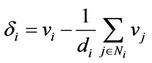
Let the initial source mesh MS be described by a pair (VS, ES), where VS ={v1, v2,  , vn} describes the geometric positions of the vertex points in R3 and ES describes the connectivity. The neighborhood ring of a vertex point i is the set of adjacent vertex points
  and the degree di of this vertex point is the number of elements in NS,i. Instead of using absolute coordinates VS, the mesh geometry is described as a set of differentials Δ =
 ,
,  is the coordinate i, which will be represented by the difference between vi and the average of its neighbors:
 (2)
(2)
The deformed mesh can be generated by minimizing the quadratic energy function:
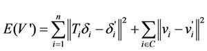 (3)
(3)
where,  ' is Laplacian coordinate after deformation and vi' is Cartesian coordinate after deformation, C is the set of control points, Ti is transformation matrix for each vertex point i. The first half is to keep the similarity of the current shape and the shape generated in the previous time step and the second half try to move control points to target position. We chosed n equals 420 to present the prostate mesh model and 84 points were selected as the control points which was explained in Section 2.3.
Ti needs to be well constrained to avoid a membrane solution, which shows losing all geometric details. Because of this Ti should include rotation, isotropic scales and translations, we find anisotropic scales should not be allowed, as they will allow removing the normal component from Laplacian coordinates. Specifically, Ti is defined as:
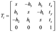 (4)
(4)
This matrix is a good linear approximation for rotations with small angles. Furthermore, it only allows isotropic scales by enforcing the same values for diagonal elements.
The quadratic energy function can be minimized iteratively by finding s, h and t for Ti and applying the transformation on each vertex coordinates. We use the changing of residuals as the convergence criterion. When its value is smaller than a threshold (e.g., 1E - 6), we assume that the system converges and this minimization problem is solved. Note that the transformation Ti is an approximation of the isotropic scaling and rotations when the rotation angle is small. In this paper, the major rotation has been handled in the global deformation so that the local rotation fits the small angle assumption well.
2.4.2.2. Local Deformation Using Laplacian Surface Optimization (LSO)
LSO is used to improve triangle quality of a surface mesh. The inputs are landmark points and the initial surface mesh and the output is an optimized surface mesh. We will use the same notation as in Section 2.5.2.1.
Assume V is the matrix representation of VS. The transformation between vertex coordinates V and Laplacian coordinates Δ can be described in matrix algebra. Let N be the mesh adjacency matrix and D = diag(d1, ···, dn) be the degree matrix. Then,  , where
  for the uniform weights.
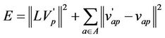
Using a subset  of m landmark points, a mesh can be reconstructed from connectivity information alone. Here the selection of A is the same as the control points selected in II.E.2.1. Positions of the reconstructed object
  can be solved separately by minimizing the quadratic energy:
 (5)
(5)
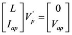
where Vp' is the vertex coordinates of the reconstructed object, vap are landmark points. The first half is Laplacian constrains to smooth the object by minimizing the difference, and the second half is positional constrains to keep landmark points unchanged. In practice, with m landmark points, the  overdetermine linear system:
 (6)
(6)
is solved in the least squares method using the method of normal equations . The first n rows of
  are the Laplacian constrains, corresponding to the first part
 , while the next m rows are the positional constrains, corresponding to the second part
  .
.
Iap is the index matrix of vap, which maps each v'ap to vap. The reconstructed shape is generally smooth, with the possible exception of small areas around landmark points. The minimization procedure moves each vertex point to the centroid of its ring, since the uniform Laplacian L is used, resulting in good inner fairness. The main computation cost of this algorithm is big matrix multiplication and inverse. Since A is sparse matrix, ATA is sparse symmetric definite matrix. The conjugate gradient algorithm can be employed to solve the system.
3. Validation Studies
The quantitative validation of the proposed deformable registration algorithm for prostate cancer image volumes was designed to include three components: distancebased estimators, volume-based estimators and registration efficiency. For all three evaluations, the proposed method was compared against the corresponding benchmarks as well as the registration results obtained using our previous deformable mesh model based image Registration method.
The Distance-Based Estimators and the Volume-Based Estimators
The distance-based estimators include the mean distance and the root mean square error (RMSE). The mean distance, the root-mean-square error (RMSE) and the max distance are calculated the corresponding prostate points between the treatment CBCT images and the registered planning images. The corresponding prostate points include two parts of points, corresponding landmark points and corresponding non-landmark points. The corresponding landmark points was acquired for the global registration step in the Sections 2.3. and 2.4. The corresponding non-landmark points which are defined as the closest point to the original mesh point.
The volume-based estimators include the volumetric true positive (TP), volumetric false negative (FN), volumetric the false positive (FP) and Dice similarity coefficient
between the results of proposed deformable registration method and benchmarks. We used this similarity measure since it accurately reflected the overall volumetric overlapping between binary objects and also included the information about the major causes of the differences, such as overestimate or underestimate.
4. Results
4.1. Qualitative Results and Quantitative Results of Proposed Registration Method
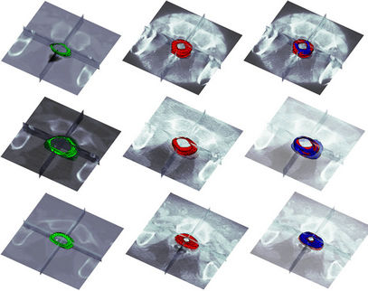
Figure 3 displays the qualitative results of the proposed method applied to three of the datasets. The prostate benchmarks from the planning CT and the treatment CBCT are shown in Figures 3 (a) and (b), respectively. The prostates in column (a) were correspondingly registered to column (b) using the proposed method. Figure 3 (c) shows the registered prostates (in blue) superimposed on the corresponding prostate benchmarks from the treatment CBCT images. Figure 4 shows the axial view of the enlarged image results of Figure 3. Figure 5 shows the spatial error (red lines) between themesh point of the registered model (blue) from pCT images and the closest point of the segmented prostate model from CBCT images.
The quantitative results are summarized in Table 1 and Table 2. Table 1 shows the values of the mean distance (ranged from 0.43 mm to 2.23 mm), the rootmean-square error (RMSE) (ranged from 0.51 mm to 2.46 mm) and the max distance (ranged from 2.48 mm to 5.32 mm) of the corresponding prostate points between the treatment CBCT images and the registered planning images using the proposed deformable registration method. Table 1 also shows the values of the mean distance (ranged from 0.38 mm to 2.20 mm), the root-mean-square error (RMSE) (ranged from 0.45 mm to 2.36 mm) and the max distance (ranged from 1.59 mm to 5.98 mm) of the corresponding prostate points between the treatment CBCT images and the registered planning images using the previous deformable mesh model based image registration method [26]. These results demonstrate that the developed method produced reasonably good agreement between the registered prostates and the corresponding benchmarks using the distance-based estimators.
 (a) (b) (c)
Figure 3. Deformable registration results of Laplacian surface deformation and optimization: (a) segmented prostate model (green) from planning CT images; (b) segmented prostate model (red) from CBCT images; and (c) registered model (blue) superimposed on (b).
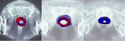
Figure 4. The enlarged image results of the axial view of of Figure 3. The registered model (blue) from pCT images superimposed on the segmented prostate model (red) from CBCT images using Laplacian surface deformation and optimization deformable registration.

Figure 5. The spatial error (red lines) between the mesh point of the registered model (blue) in the pCT images and the corresponding closest mesh point of the segmented prostate model of CBCT images.
Table 2 shows the values of the volumetric false positive volumetric true positive (TP ranged from 84.5% to 93.7%) and Dice similarity coefficient (ranged from 85.5% to 93.2%) between the results of proposed deformable registration method and benchmarks. Table 2 also shows the values of the volumetric false positive (volumetric FP ranged from 7.53% to 14.56%), volumetric false negative (FN ranged from 5.03% to 14.8%), volumetric true positive (TP ranged from 85.2% to 94.97%) and Dice similarity coefficient (ranged from 86.0% to 93.8%) between the results of the previous deformable mesh model based registration method and benchmarks. These results further confirm that the developed method produced reasonably good agreement between the registered prostates and the corresponding benchmarks.

Table 1. Quantitative comparison results of the proposed deformable registration method based on the Laplacian surface deformation and Laplacian surface optimization on 8 clinical datasets to those of the benchmarks on the CBCT images. Quantitative comparison results of previous deformable mesh model based image registration method on 8 clinical datasets to those of the benchmarks on the CBCT images. The distance based estimators include mean distance, root-mean-square error (RMSE) and maximum distance.

Table 2. Quantitative comparison results of the proposed deformable registration method based on the Laplacian surface deformation and Laplacian surface optimization on 8 clinical datasets to those of the benchmarks on the CBCT images. Quantitative comparison results of previous deformable mesh model based image registration method on 8 clinical datasets to those of the benchmarks on the CBCT images. The volume based estimators include the volumetric true positive (TP), volumetric false negative (FN), volumetric the false positive (FP) and Dice similarity coefficient between the results of proposed deformable registration method and benchmarks.
4.2. Registration Processing Efficiency
All the implementation of the algorithm was written in C/C++ and MATLAB. The software package was installed on a Dell Pentium PC station running Windows XP. The CPU was Intel(R) at 2.66 GHz and the RAM size was 4GB.
The time expenses of the global-to-local registration for all 8 data sets (cropped around the volume of interest and the dimension of the largest volume of interest is 150 × 150 × 100 pixels) were summarized in Table 3.The preprocessing time (image resampling, image contrast enhancement, rigid alignment, cropping the volume of interest) was about 60 seconds if used by a person who was familiar with the Varian Medical Systems, our in-house software package and Matlab. The entire registration processing time was within half minute for all the 8 datasets. The average duration time of the global transformation in the proposed registration method was from 3.2 seconds to 4.9 seconds, the average duration time of the LSE of the local transformation was from 2.0 seconds to 3.2 seconds and the average duration time of the LSO of the local transformation was from 10.3 seconds to 15.4 seconds.
Table 3 also presents the average duration time of the global transformation using the deformable mesh model based registration method. The time ranged from 137 seconds to 246 seconds, with the average duration time of the local transformation ranging from 20 seconds to 34 seconds.
It is apparent that the speed of the entire process was significantly improved with the proposed registration method.
5. Discussion and Conclusions
The motivation of this paper is to develop a deformable registration method fast enough for routine clinical use, such as pretreatment positioning correction and adaptive plan modification. In one of our previous studies [26], a global-to-local deformable registration was developed. In that method, the global registration was achieved by maximizing the mutual information between the source volume and target volume. The local registration process implicitly used the information of the segmented volume by fitting deformable superellipsoid mesh models and minimizing the Euclidian distance of the corresponding nodal points from the global. However, the performance of the previous method could not meet the restricted treatment time requirement. To overcome the shortcoming of the previous method, we developed this new global-to-local deformable registration method which incorporated both computationally efficient landmark points based global registration method and a new computationally efficient Laplacian surface deformation (LSD) and Laplacian surface optimization (LSO) based local registration algorithm.
The registration method developed in this paper distinguishes itself from the previous one in both the global registration process and the local registration process. In the global registration the current method was to find an optimal similarity transformation based on the two sets of corresponding landmark points by minimizing the least square function. The speed of current method global registration process is significantly faster than that of volume based mutual information method. In the local registration process, the current method used Laplacian surface deformation and Laplacian surface optimization. Laplacian surface deformation has many advantages compared to deformable superquadric mesh models. It overcomes the over-deformation problem, works for large scale deformations and handles the irregular deformable mesh models. Laplacian surface optimization improves triangle quality of a surface mesh and also preserves the details when improving the mesh quality by selecting different weights (uniform, cotangent, voronoi area).

Table 3. Comparison registration time of the proposed global-to-local registration method and the previous deformable mesh model registration method for all 8 data sets (cropped around the volume of interest).
Compared to some of the current image registration methods for deformable prostate, the method developed in this study is advantageous in that it is automatic in registration without compromising the efficiency and accuracy. In a study by Alterovitz et al. [15], magnetic resonance images were registered with biomechanical modeling and nonlinear parameter estimation. In that method, only 2D image registration was involved. The manual selection of the corresponding image slices at the same level and the manual segmentation of the selected images can lead to computational inefficiency. Venugopal et al. [19] proposed a method combining magnetic resonance spectroscopic images of the prostate with anatomical MRI images based on thin-plate splines with a manual selection of control points. The main concern related to this method is the reliability of the manual selection of control points which can be time consuming and erroneous. Godley et al. [21] combined a demons algorithm and the use of masks to register large deformations in the prostate region. Due to large organ deformation in the pelvis region, that demons algorithm heavily relied on the manually segmented masks to recover the deformation.
Our results show that the proposed method is robust, reasonably fast, and accurate for the registration of the deformable soft tissue of prostate. It is believed that additional speed improvement can be achieved by implementing more advanced hardware and optimizing software performance. Furthermore, the advancement of imaging technology and improvement of CBCT image quality may well help to expedite the process. The developed method has the potential to be clinically useful to achieve real time pretreatment adaptive plan modification and more accurate patient positioning corrections. It may also be very useful in post-treatment dose accumulation calculation to provide efficient and more accurate dose coverage assessment.
6. Acknowledgements
This research project is partially supported by a grant from New Jersey Commission on Cancer Research and a grant from Varian Medical Systems.
REFERENCES
- A. Jemal, R. Siegel, E. Ward, Y. P. Hao, J. Q. Xu, T. Murray and M. J. Thun, “Cancer Statistics, 2008,” CA: A Cancer Journal for Clinicians, Vol. 58, No. 2, 2008, pp. 71-96. doi:10.3322/CA.2007.0010
- L. J. Bos, J. van der Geer, M. van Herk, B. J. Mijnheer, J. V. Lebesque and E. M. F. Damen, “The Sensitivity of Dose Distributions for Organ Motion and Set-Up Uncertainties in Prostate IMRT,” Radiotherapy & Oncology, Vol. 76, No. 1, 2005, pp. 18-26. doi:10.1016/j.radonc.2005.06.010
- T. S. Hong, W. A. Tomé, R. J. Chappell, P. Chinnaiyan, M. P. Mehta and P. M. Harari, “The Impact of Daily Setup Variations on Head-and-Neck Intensity-Modulated Radiation Therapy,” International Journal of Radiation Oncology, Biology and Physics, Vol. 61, No. 3, 2005, pp. 779-788. doi:10.1016/j.ijrobp.2004.07.696
- V. Rudat, P. Schraube, D. Oetzel, D. Zierhut, M. Flentje and M. Wannenmacher, “Combined Error of Patient Positioning Variability and Prostate Motion Uncertainty in 3D Conformal Radiotherapy of Localized Prostate Cancer,” International Journal of Radiation Oncology, Biology and Physics, Vol. 35, No. 5, 1996, pp. 1027-1034. doi:10.1016/0360-3016(96)00204-0
- M. Roach III, P. Faillace-Akazawa and C. Malfatti, “Prostate Volumes and Organ Movement Defined by Serial Computerized Tomographic Scans during Three-Dimensional Conformal Radiotherapy,” Radiation Oncology Investigations, Vol. 5, No. 4, 1997, pp. 187-194. doi:10.1002/(SICI)1520-6823(1997)5:4<187::AID-ROI4>3.0.CO;2-U
- T. R. Mackie, J. Kapatoes, K. Ruchala, W. G. Lu, C. Wu, G. Olivera, L. Forrest, W. Tome, J. Welsh, R. Jeraj, P. Harari, P. Reckwerdt, B. Paliwal, M. Ritter, H. Keller, J. Fowler and M. Mehta, “Image Guidance for Precise Conformal Radiotherapy,” International Journal of Radiation Oncology, Biology and Physics, Vol. 56, No. 1, 2003, pp. 89-105. doi:10.1016/S0360-3016(03)00090-7
- M. Berger and G. Gerig, “Motion Measurements in Low-Contrast X-ray Imagery,” Proceedings of the 1st International Conference on Medical Image Computing and Computer-Assisted Intervention, 1998, pp. 832-841.
- K. G. A. Gilhuijs, P. J. H. van de Ven and M. van Herk, “Automatic Three-Dimensional Inspection of Patient Setup in Radiation Therapy Using Portal Images, Simulator Images, and Computed Tomography Data,” Medical Physics, Vol. 23, No. 3, 1996, pp. 389-399. doi:10.1118/1.597801
- P. Viola and W. M. Wells III, “Alignment by Maximization of Mutual Information,” International Journal of Computer Vision, Vol. 24, No. 2, 1997, pp. 137-154. doi:10.1023/A:1007958904918
- R. Bansal, L. Staib, Z. Chen, A. Rangarajan, J. Knisely, R. Nath and J. Duncan, “A Minimax Entropy Registration Framework for Patient Setup Verification in Radiotherapy,” Computer Aided Surgery, Vol. 4, No. 6, 1999, pp. 287-304. doi:10.3109/10929089909148182
- R. Bansal, L. H. Staib, Z. Chen, A. Rangarajan, J. Knisely, R. Nath and J. S. Duncan, “Entropy-Based, Dual-Portalto-3DCT Registration Incorporating Pixel Correlation,” IEEE Transactions on Medical Imaging, Vol. 22, No. 1, 2003, pp. 29-49. doi:10.1109/TMI.2002.806430
- S. Chelikani, K. Purushothaman, J Knisely, Z. Chen, R. Nath, R. Bansal and J. Duncan, “A Gradient Feature Weighted Minimax Algorithm for Registration of Multiple Portal Images to 3DCT Volumes in Prostate Radiotherapy,” International Journal of Radiation Oncology, Biology and Physics, Vol. 65, No. 2, 2006, pp. 535-547. doi:10.1016/j.ijrobp.2005.12.032
- L. E. Court and L. Dong, “Automatic Registration of the Prostate for Computed-Tomography-Guided Radiotherapy,” Medical Physics, Vol. 30, No. 10, 2003, pp. 2750- 2757. doi:10.1118/1.1608497
- Y. Chi, J. Liang and D. Yan, “A Material Sensitivity Study on the Accuracy of Deformable Organ Registration Using Linear Biomechanical Models,” Medical Physics, Vol. 33, No. 2, 2006, pp. 421-433. doi:10.1118/1.2163838
- R. Alterovitz, K. Goldberg, J. Pouliot, I. C. Hsu, Y. Kim, S. M. Noworolski and J. Kurhanewicz, “Registration Of MR Prostate Images With Biomechanical Modeling And Nonlinear Parameter Estimation,” Medical Physics, Vol. 33, No. 2, 2006, pp. 446-454. doi:10.1118/1.2163391
- D. Yan, D. A. Jaffray and J. W. Wong, “A Model to Accumulate Fractionated Dose in a Deforming Organ,” International Journal of Radiation Oncology, Biology and Physics, Vol. 44, No. 3, 1999, pp. 665-675. doi:10.1016/S0360-3016(99)00007-3
- L. Xiong, A. Viswanathan, A. J. Stewart, L. M. Chin, R. A. Cormack, S. Haker and C. M. Tempany, “Deformable Structure Registration of Bladder through Surface Mapping,” Medical Physics, Vol. 33, No. 6, 2006, pp. 1848- 1856. doi:10.1118/1.2198192
- E. M. V. Osorio, M. S. Hoogeman, L. Bondar, P. C. Levendag and B. J. M. Heijmen, “A Novel Flexible Framework with Automatic Feature Correspondence Optimization for Nonrigid Registration in Radiotherapy,” Medical Physics, Vol. 36, No. 7, 2009, pp. 2848-2859. doi:10.1118/1.3134242
- N. Venugopal, B. McCurdy, A. Hnatov and A. Dubey, “A Feasibility Study to Investigate the Use of Thin-Plate Splines to Account for Prostate Deformation,” Physics in Medicine and Biology, Vol. 50, No. 12, 2005, pp. 2871- 2885. doi:10.1088/0031-9155/50/12/010
- W. Song, E. Wong, G. S. Bauman, J. J. Battista and J. Van Dyk, “Dosimetric Evaluation of Daily Rigid and Nonrigid Geometric Correction Strategies during On-Line Image-Guided Radiation Therapy (IGRT) of Prostate Cancer,” Medical Physics, Vol. 34, No. 1, 2007, pp. 352-365. doi:10.1118/1.2405325
- A. Godley, E. Ahunbay, C. Peng and X. A. Li, “Automated Registration of Large Deformations for Adaptive Radiation Therapy of Prostate Cancer,” Medical Physics, Vol. 36, No. 4, 2009, pp. 1433-1441. doi:10.1118/1.3095777
- D. Yang, S. R. Chaudhari, S. M. Goddu, D. Pratt, D. Khullar, J. O. Deasy and I. El Naqa, “Deformable Registration of Abdominal Kilovoltage Treatment Planning CT and Tomotherapy Daily Megavoltage CT for Treatment Adaptation,” Medical Physics, Vol. 36, No. 2, 2009, pp. 329-338. doi:10.1118/1.3049594
- X. L. Huang, N. Paragios and D. Metaxas, “Shape Registration in Implicit Spaces Using Information Theory and Free Form Deformations,” IEEE Transactions on Pattern Analysis and Machine Intelligence, Vol. 28, No. 8, 2006, pp. 1303-1318.
- W. H. Greene, S. Chelikani, X. Papademetris, J. P. S. Knisely and J. Duncan, “A Constrained Non-Rigid Registration Algorithm for Application in Prostate Radiotherapy,” IEEE International Symposium on Biomedical Imaging, Arlington, 12-15 April 2007, pp. 740-743.
- D. Paquin, D. Levy and L. Xing, “Multiscale Registration of Planning CT and Daily Cone Beam CT Images for Adaptive Radiation Therapy,” Medical Physics, Vol. 36, No. 1, 2009, pp. 4-11. doi:10.1118/1.3026602
- J. H. Zhou, S. Kim, S. Jabbour, S. Goyal, B. Haffty, T. Chen,
 L. Levinson, D. Metaxas and N. J. Yue, “A Deformable Model-Based 3D Registration Algorithm for Image Guided Prostate Radiotherapy,” Medical Physics, Vol. 37, No. 3, 2010, pp. 1298-1308.
 - O. Sorkine, D. Cohen-Or, Y. Lipman, M. Alexa, C. Rössl and H.-P. Seidel, “Laplacian Surface Editing,” Proceedings of the 2004 Eurographics/ACM SIGGRAPH Symposium on Geometry Processing, New York, 2004, pp. 175-184.
- A. Nealen, T. Igarashi, O. Sorkine and M. Alexa, “Laplacian Mesh Optimization,” GRAPHITE: Proceedings of the 4th International Conference on Computer Graphics and Interactive Techniques in Australasia and Southeast Asia, New York, 29 November-2 December 2006, pp. 381-389.