Advances in Nanoparticles
Vol. 2 No. 4 (2013) , Article ID: 38363 , 5 pages DOI:10.4236/anp.2013.24042
Synthesizing Nanoparticles Using Reactions Occurring in Aerosol Phases
1Department of Chemistry, State University New York at Buffalo, Buffalo, NY, USA
2Stanley Bruckenstein Chemical Consulting and Services, LLC, Williamsville, NY, USA
Email: hyoo2002@gmail.com, chemconserv@gmail.com
Copyright © 2013 Ho Yeon Yoo, Stanley Bruckenstein. This is an open access article distributed under the Creative Commons Attribution License, which permits unrestricted use, distribution, and reproduction in any medium, provided the original work is properly cited.
Received July 11, 2013; revised August 20, 2013; accepted September 8, 2013
Keywords: Nanoparticle Synthesis; Aerosols; Silver Chromate; Luminol; Umbelliferone
ABSTRACT
Our ultimate objective is to form nanoparticles by merging oppositely charged nanodroplets containing different constituents of the nanoparticle and construct a desktop apparatus to do this. These nanodroplets will be in oppositely charged aerosols originating from oppositely charged solutions containing the different component of the nanoparticle. In this paper, as the first stage in establishing the feasibility of this concept, we demonstrate that droplets formed from uncharged solutions will merge and the product of such reactions is the same as when their bulk solutions are mixed. We demonstrate that this is the case for three classes of reactions: the chemiluminescent reaction between Luminol and Potassium Ferricyanide, the pH sensitive fluorescence of Umbelliferone and the precipitation of Silver Chromate by reaction of Silver Nitrate with Potassium Chromate. We present arguments that our future goal using oppositely charged droplets is more efficient synthetically and will produce a narrow distribution of nanoparticle sizes.
1. Introduction
1.1. Concept
We propose a novel, versatile method of synthesizing nanoparticles and outline it here. Figure 1 is a block diagram illustrating the overall concept. Our approach is based on using the two nebulizers and electrical circuitry to produce aerosols having oppositely charged monodisperse drops. Each aerosol will originate from two solutions containing at least one of the nanoparticles’ soluble precursors with concentration ratios required by the stoichiometry of the reaction forming the target nanoparticles. The two aerosols will be mixed in a Reaction Phase and only the oppositely charged aerosol drops will merge. Their contents will react to produce the nanoparticles in a larger uncharged drop containing the soluble products of reaction. A carrier gas will transport the mixture of drops through an electrostatic filter that allows only uncharged drops to pass. The uncharged drops will then be introduced into the Processing-Phase to remove volatile reaction products. Evaporation of the uncharged drops in the Processing Phase will increase the internal drop pressure applied to its contents (via the inverse drop radius surface arising from the surface tension effect). This will increase the rates of any 2nd and higher order reactions. The resultant droplets containing only the nanoparticles are then transported to the Collecting Phase. Details of the processes occurring in the various Phases are discussed below.
Our proposed method differs from the approach of Salata [1] who used a single electrospray to create an aerosol of drops having several charges of the same sign that contained one component of a nanoparticle. These drops were then exposed to an excess of a reactive gas that reacted with the species in the charged drops to form nanoparticles. In our approach the masses of the nanoparticles is determined by the mass of the species that react
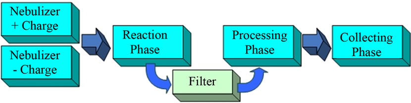
Figure 1. Synthesis scheme for nanoparticles production.
in the two oppositely charged drops when they merge together.
In Section 2, we give our initial approach using two uncharged aerosols and the results we have obtained by merging them. In Section 3, we describe our future plans and their rationale.
1.2. Background
The production of nanoparticles starting with a solution of species in a nanodroplet has developed over the past two decades [2,3]. These original studies used several methods to produce nanodroplets, e.g. by ultrasonification [4,5], electro spraying [6,7] and various thermal methods [8,9]. Evaporation of solution droplets created in these different ways produced a solid whose size was determined by the precursor masses in a droplet [10,11]. Frequently, during the latter step Chemical Vapor Deposition (CVD) was used to produce the final nanoparticle. CVD involves thermal heating to evaporate the liquid in a droplet in order to pyrolyze (sinter) intermediates in the final nanoparticle [12]. We have cited only a selected number of the fairly large literature papers using the just described approaches and their many possible combinations. Our concept described above in Section 1.1 differs from all the prior approaches in that of the final nanoparticle requires the merger of two nanodroplets as the first step in its formation. This two drop approach allows the direct formation of nanoparticle composition that is not possible using a classical single drop technique.
2. Experimental Results
2.1. Preliminary Experiments
We carried out experiments designed to validate the concept of producing nanoparticles by merging two oppositely charged drops to produce a product that would convert to nanoparticles.
These initial experiments were unsophisticated and used inexpensive commercial ultrasonic humidifiers to generated uncharged aerosols. Also, QCM equipment in out laboratories designed for other purposes was used. The objective of these experiments was to demonstrate that reactions do occur rapidly on mixing two uncharged aerosols produced from dilute solutions. The experiments we report in Sections 2.1.1 and 2.1.2 involve visual detection of a reaction product produced by the merger of aerosol drops.
2.1.1. Luminol
This experiment involved the oxidation of Luminol by potassium ferricyanide to produce light as shown in Figure 2. Initially, a solution containing Luminol and one containing potassium ferricyanide were nebulized and their aerosols were not mixed. No visible light was seen in each case in the Reaction Phase chamber. Next, the two solutions were nebulized and merged together in the Reaction Phase chamber to determine if the amino dicaboxylate anion of Luminol formed in the merged drops. A bright yellow light was observed where the aerosols droplets merged. This is the expected result that accompanies the formation of the amino dicaboxylate anion.
2.1.2. Umbelliferone
This compound is a weak monoprotic Brönsted acid that is not fluorescent in acid solutions below pH = 8 when a solution containing it is exposed the UV radiation it is a singly charged, green fluorescent anion. First, we illuminated the aerosol produced from a slightly acid umbelliferone, HB, solution with UV and there was no visible green fluorescence emerging from the HB solution (Figure 3).
Second, we merged aerosols from this slightly acid solution of umbelliferone with one from a basic (pH = ~12) sodium carbonate solution. This produced the conjugate base anion of umbelliferon and a green fluorescence typical of the umbelliferone anion was seen when UV light illuminated the region where the two aerosols merged (Figure 4). Both these above experiments show that uncharged droplets did collide, merged and made a product with the fluorescent properties we expected.
2.2. Aerosol Droplet Size Change during Nitrogen Transport from an Aerosol Generator
The purpose of these experiments was to determine if
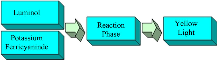
Figure 2. Chemiluminescent reaction on oxidation of Luminol.
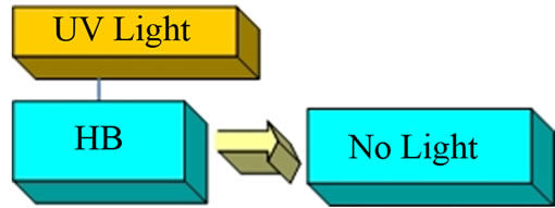
Figure 3. Umbelliferone in acid solutions.
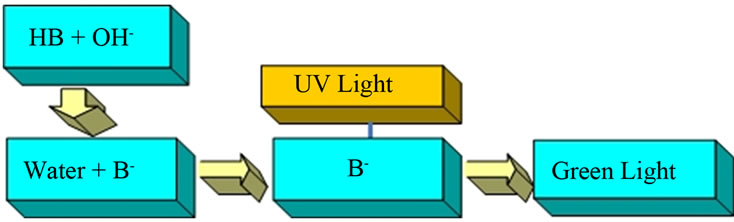
Figure 4. Umbelliferone solution pH > 8.
drop sizes within an aerosol decrease as drops are transported by the carrier gas from the point of their generation to elsewhere in the apparatus. With this goal in mind the QCM was applied to determining whether aerosol drops would evaporate in carrier gas that was not humidified.
Figure 5 is a block diagram of the experimental procedure in which first we measured the weight of solution collected for specified times by a QCM from an aerosol made from pure water and then from a sodium chloride solution that impinged on the QCM. The drops were transported through our system using ambient air flow created from the pressure difference produced with a vacuum pump.
2.2.1. Distilled Water Aerosol QCM Experiment
A blank experiment was performed with distilled water. The QCM crystal was cleaned with acetone, dried with N2 gas, and the crystal frequency was recorded. The crystal was exposed to a distilled water aerosol at one minute’s intervals for a total of eight minutes and the frequency change was recorded each time. The result of this blank experiment is shown in Figure 6. After eight minutes the frequency had decreased by 8.577 KHz. This decrease would be expected for a thickness of liquid layer on the crystal that exceeds the hydrodynamic boundary layer. Consequently the Sauerbrey equation [13] does not hold, and from Figure 6 we conclude it holds only up to four minutes.
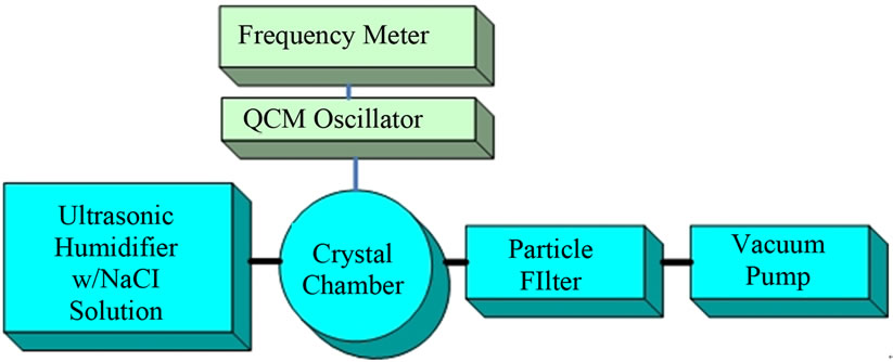
Figure 5. Experimental arrangements to measure weight of solution collected by a QCM crystal.
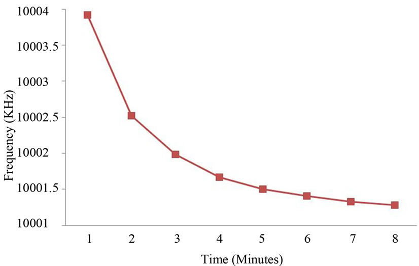
Figure 6. Frequency change in time for a distilled water flux.
2.2.2. QCM Collection of NaCl from an Aerosol Drop
Three different concentrations of NaCl were studied. The three concentrations in weight percent were 0.584 (3 expts), 2.922 (5 expts) and 5.844 (5 expts). After the aerosol drops were collected on the QCM crystal and the crystal was dried under ambient condition. These QCM frequency changes between the wet and dry crystals yielded the average weight% of NaCl in an aerosol drop.
Figure 7 is a plot of the weight% of NaCl in the solution generating an aerosol drop vs. the wt% in the NaCl drops captured by the QCM crystal. The least squares slope of this line is 3.6002 consequently the weight of NaCl in an average aerosol drop is 3.60 times that in the solution from which the aerosol was created. We interpret this to reflect evaporation of water into the ambient flowing air stream transporting the aerosol particles.
Consequently, the weight of water collected from an aerosol using a QCM is a practical way to monitor (A) the spatial distribution aerosol drops in an apparatus and (B) the acceleration of slow kinetic processes because of the increase in concentration of the reactants as the droplets evaporate. To prevent drop evaporation it would be necessary to adjust the transporting mobile gas phase to have the same water partial pressure of as the solutions from which the aerosols are formed.
3. Future Work
3.1. Nebulizer Drop Production Using an Ultrasonic Nebulizer
We plan on using piezoelectric generation of nanoparticles from two piezoelectric sources (see Figure 1) each in conducting containers that are connected at the positive and negative potentials respectively of single controlled current power supply. We choose to use two piezoelectric nebulizers operating at the same frequency because they will produce equal micron size drops with
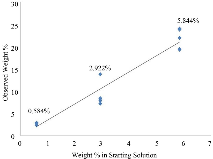
Figure 7. Observed weight% NaCl vs. starting weight% NaCl.
narrow size dispersions (Equation (1)) that can be charged to any desired magnitude by the controlled current power supply. We anticipate the latter will require relatively little current capacity but must have high voltage compliance. The power supply is a key element in our approach.
The electrical circuit is completed by using an inert carrier gas to merge the two aerosols produced by the two piezoelectric sources in the Reactant Chamber. This arrangement produces equal magnitudes of Reactant and Excess Reactant fluxes with opposite signs, i.e., anodic and cathodic fluxes.
Rajian et al. [14] developed an experimental relationship describing the dependence of the drop sizes produced by using an ultrasonic nebulizer.
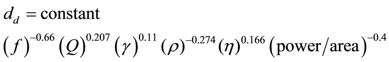 (1)
(1)
In Equation (1) dd is the drop diameter [m] that is produced, f is frequency of the ultrasonic transducer [Hz], Q is the liquid consumption rate [m3/s] (and depends on the power level), γ is surface tension of the liquid [N/m]. ρ is density of solid in the drop [kg/m3] and η is viscosity of liquid that produces the aerosol [N s/m2]2. This equation shows how the size of drops can be controlled conveniently using experimentally controllable variables.
Wang et al. [15] tested this equation by measuring drop size dispersion resulting by changing the various parameters in Equation. They studied the size dispersion of drops with sizes on the order of microns using a nebulizer operating at 1.6 MHz. As we gain experience, we intend to modify the commercial nebulizers to operate in the 10 MHz range with solutions that have 10−6 solute volume/solution volume concentrations in order to produce nanoparticles as small as ~10 nanometers.
3.2. Aerosol Formation Phase
Nebulizer Details
One nebulizer will contain a solution of the reactions’ Limiting-Reagent and the other will contain the Excess-Reagent. The conducting containers of the nebulizers’ aerosol will be the electrodes that charge their solutions oppositely and the drops leaving the surface of solutions will be entrained in the inert carrier gas. This will produce aerosols containing oppositely charged, monodisperse drops (see Section 3). The charged aerosols will be transported through the apparatus using the inert carrier gas, Helium and will be mixed in a Reaction-Phase Chamber.
The relative fluxes of the oppositely charged aerosols entering the Reaction Phase Chamber will be adjusted for the chosen charge density conditions by varying current used to generate them in nebulizer reservoirs.
3.3. Reaction Phase
In this Phase, oppositely charged drops are transported by the carrier gas from the two nebulizers and mixed in a Reaction Chamber. There the positive and negative drops containing the components of the nanoparticles merge preferentially to form uncharged larger drops that contain the nanoparticles. The probability of these uncharged drops coalescing further with each other drops are small. Any oppositely charged drops that have not yet coalesced together will be removed by a Filter stage on being transported from the Reaction Phase Chamber to the Collection Phase.
3.4. Filter Phase
The Filter comprises a pair of potential positive and negative electrodes with a high enough potential difference them to collect charged particles, but not large enough to charge the neutral particles containing the nanoparticles. The geometry of these electrodes will be such that the transit time of drops entering and leaving the filter will be long compared to the time required for all charged drops in the carrier gas to reach an electrode Liquids formed from the scavenged droplets will be collected and processed appropriately. Consequently only uncharged droplets containing the nanoparticles will exit to the Processing Phase Chamber.
3.5. Processing Phase
Drops reaching the Processing Phase Chamber will pass through a region that evaporates solvent and other volatile species that may exist in the uncharged drops because they were formed along with the nanoparticles. Additional chemical steps may also be carried out either before or after heating the aerosol to produce the dry nanoparticles that can be collected in a form for their intended use. For an example, Ag(NH3)2Cl nanoparticles could be produced in this Processing Phase by exposing an uncharged drop containing nanoparticles of AgCl to NH3 gas.
Appropriate heat treatment in this zone could convert nanoparticles synthesized in the Reaction Phase to other compounds by thermal treatment, e.g., calcium oxalate, magnesium ammonium phosphate and ferric bicarbonate to nanoparticles of calcium carbonate, magnesium pyrophosphate and Fe2O3 respectively.
If desired films of nanoparticles on a substrate could be formed by impacting the carrier gas containing the uncharged drops on a substrate heated to a temperature that produces the desired chemical nano-film composition.
4. Conclusion
Monodisperse nanoparticles can be produced by merging nanodrops in one aerosol with nanodrops in another aerosol. The merging of the two nanodrops yields a mixture that will react to form a product whose mass is determined by the masses of the reactants in the merged drop. Our goal is to assemble a compact desk top apparatus that will carry out the production of the necessary charged aerosols, merging them, and separating the resultant nanoparticles from solvent and reaction byproducts.
REFERENCES
- O. V. Salata, “Tools of Nanotechnology: Electrospray,” Current Nanoscience, Vol. 1, No. 1, 2005, pp. 25-33. http://dx.doi.org/10.2174/1573413052953192
- C. Burda, X. Chen, R. Narayanan and M. El-Sayed, “Chemistry and Properties of Nanocrystals of Different Shapes,” Chemical Reviews, Vol. 105, No. 4, 2005, pp. 1025-1102. http://dx.doi.org/10.1021/cr030063a
- J. Ho and K. Suslick, “Application of Ultrasound to the Synthesis of Nanostructured Materials,” Advanced Materials, Vol. 22, No. 10, 2010, pp. 1039-1059. http://dx.doi.org/10.1002/adma.200904093
- S. Majumdar and S. Devi, “Synthesis of SnO2 Nanoparticles Using Ultrasonication,” Proceedings of AIP Conference, Vol. 1276, No. 1, 2010, pp. 1-7. http://dx.doi.org/10.1063/1.3504298
- W. Suh and K. Suslick, “Magnetic and Porous Nanospheres from Ultrasonic Spray Pyrolysis,” Journal of the American Chemical Society, Vol. 127, No. 34, 2005, pp. 12007-12010. http://dx.doi.org/10.1021/ja050693p
- J. Suh, B. Han, K. Okuyama and M. Choi, “Highly Charging of Nanoparticles through Electrospray of Nanoparticle Suspension,” Journal of Colloid and Interface Science, Vol. 287, No. 1, 2005, pp. 135-140. http://dx.doi.org/10.1016/j.jcis.2005.01.078
- M. Gamero-Casta-icirc and V. Hruby, “Electrospray as a Source of Nanoparticles for Efficient Colloid Thrusters,” Journal of Propulsion and Power, Vol. 17, No. 5, 2001, pp. 977-987. http://dx.doi.org/10.2514/2.5858
- H. K. Kammler, L. Mädler and S. E. Pratsinis, “Flame Synthesis of Nanoparticle,” Chemical Engineering & Technology, Vol. 24, No. 6, 2001, pp. 583-596. http://dx.doi.org/10.1002/1521-4125(200106)24:6<583::AID-CEAT583>3.0.CO;2-H
- I. Taniguchi, “Physical and Electrochemical Properties of Spherical Nanostructured LiCrxMn2-xO4 Particles Synthesized by Ultrasonic Spray Pyrolysis,” Industrial & Engineering Chemistry Research, Vol. 44, No. 17, 2005, pp. 6560-6565. http://dx.doi.org/10.1021/ie048740u
- K. Yasuda, Y. Bando, S. Yamaguchi, M. Nakamura and A. Oda, “Analysis of Concentration Characteristics in Ultrasonic Atomization by Droplet Diameter Distribution,” Ultrasonics Sonochemistry, Vol. 12, No. 1-2, 2005, pp. 37-41. http://dx.doi.org/10.1016/j.ultsonch.2004.05.008
- D. J. McClements, “Principles of Ultrasonic Droplet Size Determination in Emulsions,” Langmuir, Vol. 12, No. 14, 1996, pp. 3454-3461. http://dx.doi.org/10.1021/la960083q
- K. Okuyama and I. W. Lenggoro, “Preparation of Nanoparticles via Spray Route,” Chemical Engineering Science, Vol. 58, No. 3-6, 2003, pp. 537-547. http://dx.doi.org/10.1016/S0009-2509(02)00578-X
- G. Sauerbrey, “The Use of Quartz Oscillators for Weighing Thin Layers and for Microweighing,” Zeitschrift für Physik, Vol. 155, No. 2, 1959, pp. 206-222. http://dx.doi.org/10.1007/BF01337937
- R. Rajan and A. B. Pandit, “Correlations to Predict Droplet Size in Ultrasonic Atomisation,” Ultrasonics, Vol. 39, No. 4, 2001, pp. 235-255. http://dx.doi.org/10.1016/S0041-624X(01)00054-3
- W. Wang, A. Purwanto, I. W. Lenggoro, K. Okuyama, H. Chang and H. D. Jang, “Investigation on the Correlations between Droplet and Particle Size Distribution in Ultrasonic Spray Pyrolysis,” Industrial & Engineering Chemistry Research, Vol. 47, No. 5, 2008, pp. 1650-1659. http://dx.doi.org/10.1021/ie070821d