Open Journal of Fluid Dynamics
Vol.4 No.2(2014), Article ID:46089,7 pages
DOI:10.4236/ojfd.2014.42012
Computational Fluid Dynamics Study on Water Flow in a Hollow Helical Pipe
Ebrahim Ahmadloo1*, Najmeh Sobhanifar2, Fatemeh Sadat Hosseini3
1Young Researchers and Elite Club, Darab Branch, Islamic Azad University, Darab, Iran
2Young Researchers and Elite Club, Shoushtar Branch, Islamic Azad University, Shoushtar, Iran
3Young Researchers and Elite Club, Shiraz Branch, Islamic Azad University, Shiraz, Iran
Email: *Ebrahimahmadloo@yahoo.com, sobhanifar.najme@yahoo.com, polytak2000@gmail.com
Copyright © 2014 by authors and Scientific Research Publishing Inc.
This work is licensed under the Creative Commons Attribution International License (CC BY).
http://creativecommons.org/licenses/by/4.0/


Received 1 April 2014; revised 1 May 2014; accepted 8 May 2014
ABSTRACT
Although curved pipes are used in a wide range of applications, flow in curved pipes is relatively less well known than that in straight ducts. This paper presents a computational fluid dynamics study of isothermal laminar single-phase flow of water in a hollow helical pipe at various Reynolds numbers. The ranging of Reynolds numbers of fluid was from 703.2 to 1687.7. The three dimensional governing equations for mass and momentum have been solved. It was found that with increasing Reynolds number and creation of centrifugal forces, a high velocity and pressure region occurs between two tubes, at the outer side of the hollow helical pipe walls. Friction factor decreases as the tendency for turbulence increases.
Keywords:Computational Fluid Dynamics, Water Flow, Hollow Helical Pipe, Pressure Gradient, Velocity

1. Introduction
Although curved pipes are used in a wide range of applications, flow in curved pipes is relatively less well known than that in straight ducts. In recent years, Helical coiled tubes have been more attention because of their practical applications such as compactness, easy manufacture and high efficiency in heat and mass transfer. They are extensively used in compact heat-exchangers, heat-exchanger network, heating or cooling coils in the piping systems, intake in air-crafts, fluid amplifiers, coil steam generators, refrigerators, nuclear reactors, thermo siphons, and other heat transfer equipment involving phase change, chemical plants as well as in the food and drug industries [1] .
In particular, helical coils are also used as steam generators in some “generation IV” nuclear reactors like IRIS [2] .
During the designing and operating processes of helical coiled tubing steam generators, the prediction of pressure drop of single-phase flow and two-phase mixtures is an essential step for the adjustment of pump pressure head and even calculation of heat transfer conditions. Despite considerable progress that has been made in the past several decades this, and many different correlations (such as that of Berger and Talbot [3] , Akagawa et al. [4] , Chen and Zhou [5] , Unal et al. [6] , Nariai et al. [7] , Watanabe et al. [8] , Guo et al. [9] ), were proposed.
Naphon and Wongwises [10] , in particular, recently reviewed more than 100 studies addressing both single and two-phase flow through curved tubes. Two-phase flow pressure drop in helical coils, in particular, received considerable attention, both in adiabatic and diabatic flow conditions.
M. Moawed [11] investigated the forced convection from helical coiled tubes with different parameters. Their results showed that, for the same P/do (Pitch of coil tube/Outer diameter of coil tube), the higher values of Nusselt number can be obtained with a high value of D/do (Coil diameter/Outer diameter of coil tube) while the small value of Nusselt number can be obtained with a small value of D/do.
Austen and Soliman [12] studied laminar flow and heat transfer in helically coiled tubes with substantial pitch. The influence of pitch on the pressure drop and heat transfer characteristics of helical coils was explored for the condition of uniform input heat flux. Water was used as the test fluid. Significant pitch effects were noted in the friction factor and Nusselt number results at low Reynolds number.
Choi et al. numerically studied the steady laminar flows in coiled hollow ducts and observed the evolution of secondary flow and the effect of radius ratio on the flow development. It was concluded that the flow in a curved hollow duct was not necessarily fully developed earlier when the radius ratio was larger owing to the complicated interaction between the viscous and centrifugal forces [13] . Hollow helical pipes could not only provide more compactness in volume, but also controlled main flow and secondary flow due to the inner-wall boundary effects, making the friction factor and heat transfer characteristics different from straight circular tubes [14] . For hollow helical pipe, the experimental results of Xin et al. indicated that the single-phase and two-phase flow pressure drops in hollow helical pipe differ from that in helical pipe with a circular cross-section [15] .
2. Analysis and Modeling
2.1. Experiment
Figure 1 shows the geometry of test section. The setup consisted of a hollow helical pipe with 9 turns, inner coil of 9.53 mm diameter (I.D.), and outer coil of 6.22 mm. The coil has stretched lengths of 2.286 m. The diameter and the pitch of the outer coil are 196.85 mm and 25.4 mm, respectively [6] .

Figure 1. The schematic of hollow helical pipe.
2.2. Governing Equations
2.2.1. Continuity Equation
 (1)
(1)
2.2.2. Momentum Equations
 (2-a)
(2-a)
 (2-b)
(2-b)
 (2-c)
(2-c)
2.3. Boundary Conditions
At the inlet according to different Reynolds numbers for laminar flow, corresponding normal speeds were used. No turbulence option was chosen for analysis (laminar flow). At outlet, pressure boundary condition was applied. No slip boundary condition was used at walls.
2.4. Solution Method
Convergence criterion of 1.0E−5 for RMS of all of the equations was used. Hybrid scheme was used for discretization of all equations and SIMPLEC algorithm was used for pressure-velocity coupling. The effect of gravitational force is applied in this analysis. In this analysis, a superficial velocity of 0.101, 0.113, 0.162 and 0.243 ms−1 for Reynolds numbers of 703.2, 787.6, 1125.3 and 1687.7 at the inlet are specified, respectively.
3. Results and Discussion
Figure 2 shows the contour plots of velocity at four positions; 1 × 180˚, 6 × 180˚, 9 × 180˚ and outlet. Four Reynolds number of 703.2, 787.6, 1125.3 and 1687.7 for laminar flow were also applied. As can be seen in the Figure 2, we have more uniformed high speed between two tubes, at the outer side of the hollow helical pipe walls, as the Reynolds number enhances. This is due to the effect of centrifugal force, but slowest speed is related to near regions to the inner tube walls. When is creating centrifugal forces, high velocity region is observed at the outer side of the hollow helical pipe, whereas in the case of flow in a straight pipe, high velocity region is observed at the centre of the pipe. The location of high velocity region shifted slightly down in successive turns of pipe, and the band of very high water velocity (dark red band) is slightly wider, too. Figure 3 shows the contour plots of pressure gradient at four positions; 1 × 180˚, 6 × 180˚, 9 × 180˚ and outlet of hollow helical pipe for water flow with 703.2, 787.6, 1125.3 and 1687.7 Reynolds numbers for laminar flow. The curvature of the pipe causes centrifugal force to act on the fluid. This leads to a higher velocity in the outer side of the pipe, as compared to the flow in a straight pipe, where high velocity region is observed at the centre of the pipe. The acceleration forces acting on the fluid flow in the pipe create high pressure region at outer side of the pipe wall. In other words, raising the pressure on the outer side of the wall caused the buoyancy forces. It was equal with 522.163, 591.548, 905.118 and 1481.64 Pascal for Reynolds numbers of 703.2, 787.6, 1125.3 and 1687.7 as calculated and depicted in Equation (3). Then friction factor was calculated from Equation (4) as its results are presented in Table 1 and Figure 4. The results were too close to the experimental data.
 (3)
(3)
The friction factor for single phase flow is determined using:
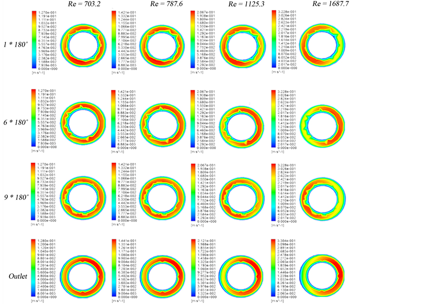
Figure 2. The contour plots of velocity at different positions.
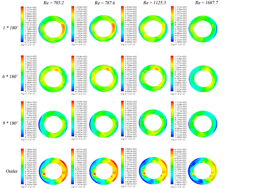
Figure 3. The contour plots of pressure gradient at different positions.
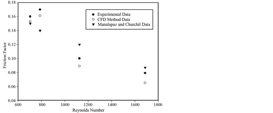
Figure 4. Friction factor of laminar single liquid phase flow of water in hollow helical pipe versus various Reynolds number.

Table 1. Values of friction factor versus Reynolds number with computed average and mean average errors.
a ; b
; b ; NP, number of data points.
 (4)
(4)
It seems that the friction factor results can be predicted with reasonable accuracy in the complete laminar flow regions. The critical Reynolds numbers predicted by Srinivasan’s equation (Srinivasan et al. 1970) is 1139 for this test section.
Figure 4 shows the values of friction factor of laminar single liquid phase flow of water in hollow helical pipe versus various Reynolds numbers, graphically. As well depicted in this figure, we computed the values of experimental data of friction factor with CFD method with a high accuracy compared with Manalapaz and Churchil method [16] .
The calculated and experimental values of friction factor with computed average and mean average errors can be observed in Table 1. The results were very satisfactory.
Therefore, we would like to present and suggest a new technique namely CFD method, for simulation and prediction of various processes in industrial applications. In this approach, we are able to design the best geometry of equipments in different industries with the highest accuracy and maximum of efficiency.
4. Conclusion
Laminar single-phase of water flow through a hollow helical pipe is simulated using computational fluid dynamics (CFD) model. It was found that centrifugal forces created a high velocity region at the outer side of the hollow helical pipe walls. The acceleration forces acting on the fluid flow in the pipe create high pressure region at outer side of the pipe wall. Friction factor decreases with tend to increasing turbulency, although the results of MAE of correlations—CFD model showed a very close values compared with experimental data.
References
- Ali, S. (2001) Pressure Drop Correlations for Flow through Regular Helical Coil Tubes. Fluid Dynamics Research, 28, 295-310. http://dx.doi.org/10.1016/S0169-5983(00)00034-4
- Carelli, M.D., Conway, L.E., Oriani, L., Petrovic, B., Lombardi, C.V., Ricotti, M.E., Barroso, A.C.O., Collado, J.M., Cinotti, L., Todreas, N.E., Grgic, D., Moraes, M.M., Boroughs, R.D., Ninokata, H., Ingersoll, D.T. and Oriolo, F. (2004) The Design and Safety Features of the IRIS Reactor. Nuclear Engineering and Design, 230, 151-167. http://dx.doi.org/10.1016/j.nucengdes.2003.11.022
- Berger, S.A., Talbot, L. and Yao, L.S. (1983) Flow in Curved Pipes. Annual Review of Fluid Mechanics, 15, 461-512. http://dx.doi.org/10.1146/annurev.fl.15.010183.002333
- Akagawa, K., Sakaguchi, T. and Ueda, M. (1971) Study on Gas-Liquid Two-Phase Flow in Helically Coiled Tubes. Bulletin of JSME, 14, 564-571. http://dx.doi.org/10.1299/jsme1958.14.564
- Chen, X.J. and Zhou, F.D. (1981) An Investigation of Flow Pattern and Frictional Pressure Drop Characteristics of Air-Water Two-Phase Flow in Helical Coils. Procceedings of the Fourth Miami International Conference on Alternate Energy Sources, 120-129.
- Unal, H.C., Van Gasself, M.L.G. and Von’t Versalt, P.M. (1981) Dryout and Two-Phase Flow Pressure Drop in Sodium Heated Helically Coiled Steam Generators Tubes at Elevated Pressure. International Journal of Heat and Mass Transfer, 24, 285-298.http://dx.doi.org/10.1016/0017-9310(81)90036-3
- Nariai, H., Kobayashi, M. and Matsuoka, T. (1982) Friction Pressure Drop and Heat Transfer Coefficient of Two-Phase Flow in Helically Coiled Tube Once-Through Steam Generator for Integrated Type Marine Water Reactor. Journal of Nuclear Science and Technology, 109, 936-947. http://dx.doi.org/10.1080/18811248.1982.9734239
- Watanabe, O., Tajima, O. and Shimoya, O. (1986) Flow and Heat Transfer of Gas and Liquid Two-Phase Flow in Helical Coils. Transactions on JSME, 52, 1857-1864. http://dx.doi.org/10.1299/kikaib.52.1857
- Guo, L.J., Chen, X.J., Zhang, S.K. and Feng, Z.P. (1994) Correlation for Predicting Pressure Drop of Single and Two-Phase Flow through Horizontal Helically Coiled Tubes. Proceedings of the Third International Symposium on Multiphase Flow and Heat Transfer, Xi’an, 514-521.
- Naphon, P. and Wongwises, S. (2006) A Review of Flow and Heat Transfer Characteristics in Curved Tubes. Renewable and Sustainable Energy Reviews, 10, 463-490.http://dx.doi.org/10.1016/j.rser.2004.09.014
- Moawed, M. (2011) Experimental Study of Forced Convection from Helical Coiled Tubes with Different Parameters. Energy Conversion and Management, 2, 1150-1156.http://dx.doi.org/10.1016/j.enconman.2010.09.009
- Austen, D.S. and Soliman, H.M. (1988) Laminar Flow and Heat Transfer in Helically Coiled Tubes with Substantial Pitch. Journal of Experimental Thermal and Fluid Science, 1, 183-194. http://dx.doi.org/10.1016/0894-1777(88)90035-0
- Choi, H.K. and Park, S.O. (1992) Laminar Entrance Flow in Curved Annular Ducts. International Journal of Heat and Fluid Flow, 13, 41-49. http://dx.doi.org/10.1016/0142-727X(92)90058-H
- Karahalios, G.T. (1990) Mixed-Convection Flow in a Heated Curved Pipe with Core. Physics of Fluids, 2, 2164-2175. http://dx.doi.org/10.1063/1.857803
- Xin, R.C., Awwad, A., Dong, Z.F. and Ebadian, M.A. (1997) An Experimental Study of Single-Phase and Two-Phase Flow Pressure Drop in Annular Helicoidal Pipes. International Journal of Heat and Fluid Flow, 18, 482-488. http://dx.doi.org/10.1016/S0142-727X(97)80006-9
- Manalapaz, R.L. and Churchill, S.W. (1980) Fully Developed Laminar Flow in a Helically Coiled Tube of Finite Pitch. Chemical Engineering Communications, 7, 57-78.http://dx.doi.org/10.1080/00986448008912549
Nomenclature
d: Diameter, m D: Coil diameter, m L: Pipe length, m P: Pressure, Pa = N/m2
Δp: Pressure difference, Pa r: Tube radius, d/2 R: Coil mean radius, D/2 X: Spatial position, m u: Velocity, m/s
Greek Symbols
 : Density of fluid, kg/m3
µ: Dynamic viscosity, Pa×s = N×s/m2
Subscripts
i: Inlet o: Outlet
Dimensionless Groups
f: Friction factor,

Re: Reynolds number,

NOTES

*Corresponding author.