Modeling and Numerical Simulation of Material Science
Vol.3 No.3(2013), Article ID:33830,4 pages DOI:10.4236/mnsms.2013.33012
CFD Analysis of Influence of Slag Viscosity on the Splashing Process in an Oxygen Steelmaking Converter
Departamento de Materiales, Universidad Autonoma Metropolitana Azcapotzalco, México D.F., México
Email: bmma@correo.azc.uam.mx, dyolotzin@correo.azc.uam.mx, ihc@correo.azc.uam.mx
Copyright © 2013 Miguel A. Barron et al. This is an open access article distributed under the Creative Commons Attribution License, which permits unrestricted use, distribution, and reproduction in any medium, provided the original work is properly cited.
Received May 7, 2013; revised June 7, 2013; accepted June 18, 2013
Keywords: CFD; Oxygen Steelmaking; Refractory Lining; Slag Viscosity; Splashing Process
ABSTRACT
Physical properties of molten slag such as viscosity, density and surface tension have a significant influence on the slag splashing process in an oxygen steelmaking converter. Particularly, viscosity determines the shear forces that rule droplets formation. Besides, stirring of the molten slag bath strongly depends on this property. In this work, the influence of viscosity on the efficiency of slag splashing is explored by means of transient Computational Fluid Dynamics simulations. Several values of viscosity are employed in the computer experiments. In order to quantify the splashing efficiency as function of slag viscosity, an average slag fraction on the converter walls is defined and calculated. CFD results are compared with those of an empirical expression, and at least qualitative agreement is found.
1. Introduction
Currently, around two thirds of the world raw steel is made using oxygen steelmaking converters. In this technology a supersonic oxygen jet is blown through a lance onto impure molten iron, and impurities are removed by oxidation, transforming in this way an impure molten iron into raw steel. To protect converters and extend their life, they are lined with expensive refractory, which suffers significant wear due to thermal, mechanical and chemical attack. In order to be competitive, corporations must necessarily reduce operation cost, and therefore techniques which allow savings in refractory costs are welcome. Slag splashing process has emerged in the last years as a promising technology that has, among others, the following advantages: improves molten steel yield, increases converter availability, decreases refractory costs, and increases the lining life [1]. In this process, a high speed gaseous nitrogen jet is blown onto molten slag located in the furnace bottom (Figure 1. where red phase is molten slag and blue phase is nitrogen), and the molten slag is splashed to the converter walls; the slag is cooled and frozen forming a protective coating on the refractory. Two splashing mechanisms are present during the process: washing and ejection. The first one is due to the bulk movement of molten slag, and the second one is due to the droplet ejection [2]. Broadly, the slag splashing process is composed of these steps: 1) tapping of molten steel from the converter vessel, 2) conditioning of molten slag by the melter, 3) lowering of the oxygen lance and injection of high speed nitrogen, 4) lance extraction and removal of remaining slag [1].
Main factors which affect the splashing process are: operating parameters (jet speed, angle of injection, lance height, molten slag height), and slag properties (viscosity, density, surface tension) [3]. Operating factors have been previously studied by two of the authors of the present work [4], however further analysis is required in order to clarify the influence of the molten slag properties on the splashing process. Shear forces required to break the molten slag bath to form drops which are ejected and adhered to the furnace walls are strongly dependent on jet speed and viscosity of molten slag. In this work the influence of slag viscosity on the splashing efficiency is analyzed by means of Computational Fluid Dynamics (CFD) simulations. An industrial furnace is geometrically modeled, and several values of viscosity are employed in the computer 2D transient simulations. First, the mathematical models employed to represent fluid flow, continuity, turbulence, boundary conditions, multiphase flow and a parameter to quantify the efficiency of the slag splashing process are presented. Then, the parameters employed in the CFD computer simulations are
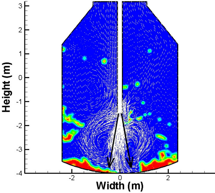
Figure 1. The slag splashing process and physical dimensions of the furnace. Red phase is molten slag, blue phase is nitrogen.
defined. Finally, the CFD results are described and discussed, and concluding remarks are presented.
2. Mathematical Model and Boundary Conditions
During the slag splashing process, molten slag located in the converter bottom is splashed to sidewalls using a gaseous nitrogen supersonic jet. Momentum of the nitrogen jet is transferred to slag, which causes the slag to be stirred and ejected by the action of a standing wave and high shear forces [5-8]. Inertial, gravitational, viscous and interfacial forces are acting on gaseous nitrogen and molten slag [9-11]. To model this complex system, equations which govern fluid flow, mass balance, turbulence and multiphase flow are required, however given their complexity, numerical solution is mandatory. The flow of an incompressible Newtonian fluid is governed by the Navier-Stokes equations [12]:
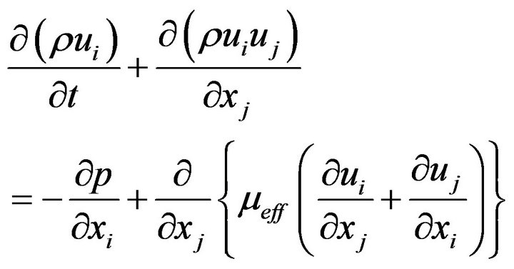 (1)
(1)
where ρ is the fluid density, ui is the ith component of the fluid velocity u, t is time, xj is j spatial coordinate, p is pressure, and μeff is the effective fluid viscosity. To maintain the mass balance in the system, the continuity equation [10] 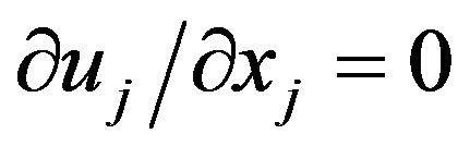 must be solved. To simplify computer simulations, turbulence can be modeled using the classical two equations K-ε model [13]:
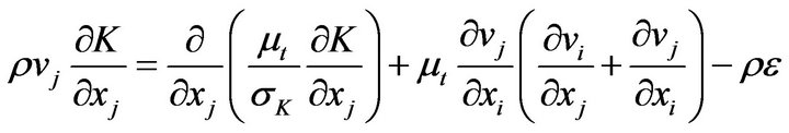 (2)
(2)
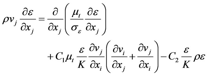 (3)
(3)
The effective viscosity μeff is determined from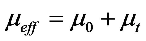 , where μ0 is the laminar viscosity and μt is the turbulent viscosity. Besides, μt is obtained from
 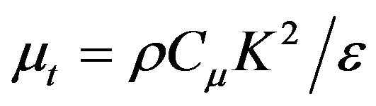 , where K and ε are calculated by solving Equations (2) and (3). Values of σK, σε, C1, C2 and Cμ are 1.0, 1.3, 1.44, 1.92 and 0.09, respectively [13]. Boundary conditions for K and ε at the inlet nozzle is calculated from
 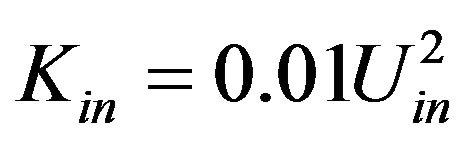 and
and  [13] where Uin and Dn are the inlet nominal velocity and the nozzle diameter, respectively. The Pressure-Implicit with Splitting of Operators (PISO) algorithm was employed for the pressure-velocity coupling [14].
On the other hand, the Volume of Fluid (VOF) model to issue the multiphase flow is based on the assumption that two or more phases are not interpenetrating. For each additional phase q its volume fraction αq is introduced as a variable. In each control volume the volume fractions of all phases sum to unity. The tracking of the interface between the phases is accomplished by solving the continuity equation for each phase [15]:
 (4)
(4)
In this work, a dimensionless parameter named as average slag volume fraction ( ) is used to evaluate quantitatively the efficiency of the slag splashing process. This parameter is determined for the left vertical sidewall, and is defined in this way:
 (5)
(5)
where vs is the local value of the slag volume fraction for a given time, and Hmin = −3.5 m and Hmax = 1.4 m (Figure 1) are the vertical coordinates of the start and end of the left vertical sidewall, respectively. The physical meaning of  corresponds to an average volume fraction of molten slag in the left sidewall due to the slag splashing by the combined action of washing and ejection mechanisms. This parameter determines the efficiency of slag splashing in this way:
  = 0 means absolutely no coating of the left sidewall, whereas
  = 1 implies full coating of the aforementioned sidewall.
3. CFD Results and Discussion
Navier-Stokes equations, turbulence model equations and VOF model equations were numerically solved using CFD software. 2D transient isothermal simulations were carried out employing a trilateral mesh with around 14,000 elements and time step of 0.0001 s. The nitrogen jet speed was fixed in a supersonic value of 510 m∙s−1, which is injected downwards with an angle of 10˚. The diameter of the two considered injection nozzles was assumed of 0.043 m. A lance height of 2 m above the slag bath and a molten slag depth of 0.5 m were assumed. For the analysis, the considered values of the molten slag viscosity were 0.01, 0.2, 0.4, 0.6, 0.8 and 1.0 kg∙m−1∙s−1. Surface tension of 0.4 N∙m−1 and density of 2500 kg∙m−3 were assumed for molten slag.
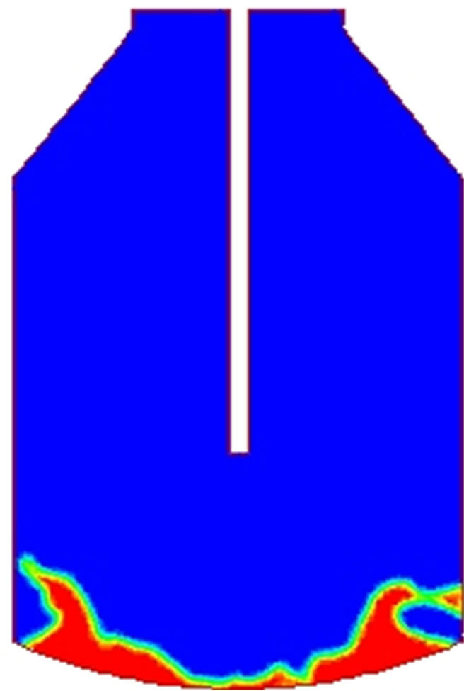
Figure 2 shows the evolution of the slag splashing process considering a viscosity value of 0.4 kg∙m−1∙s−1. Red phase is molten slag, blue phase is nitrogen. As time proceeds, the amount of slag splashed is increased. Molten slag is deposited on the cool furnace walls and adheres to them, freezing and forming a resistant coating that protects the refractory from thermal, mechanical and chemical attack.
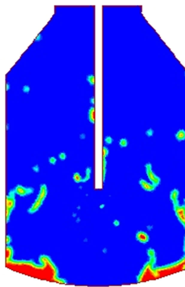
In Figure 3 is shown the distribution of phases for several values of slag viscosity, assuming an integration time of 2 s. Observing the furnace bottom, one can appreciate that more slag remains in this site as viscosity is increased. This means that less slag is ejected to the walls as viscosity is increased. On the contrary, one would expect that the more slag is ejected as droplets as viscosity decreases. This suggests that the ejection mechanism is relevant for low viscosity values, whereas the washing mechanism becomes significant for high viscosity values.
 (a)
(a)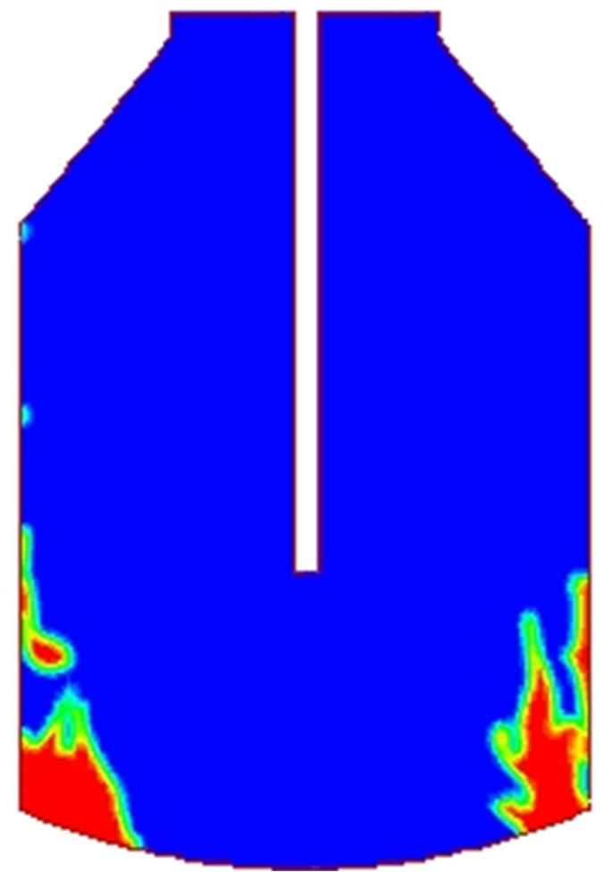 (b)
(b)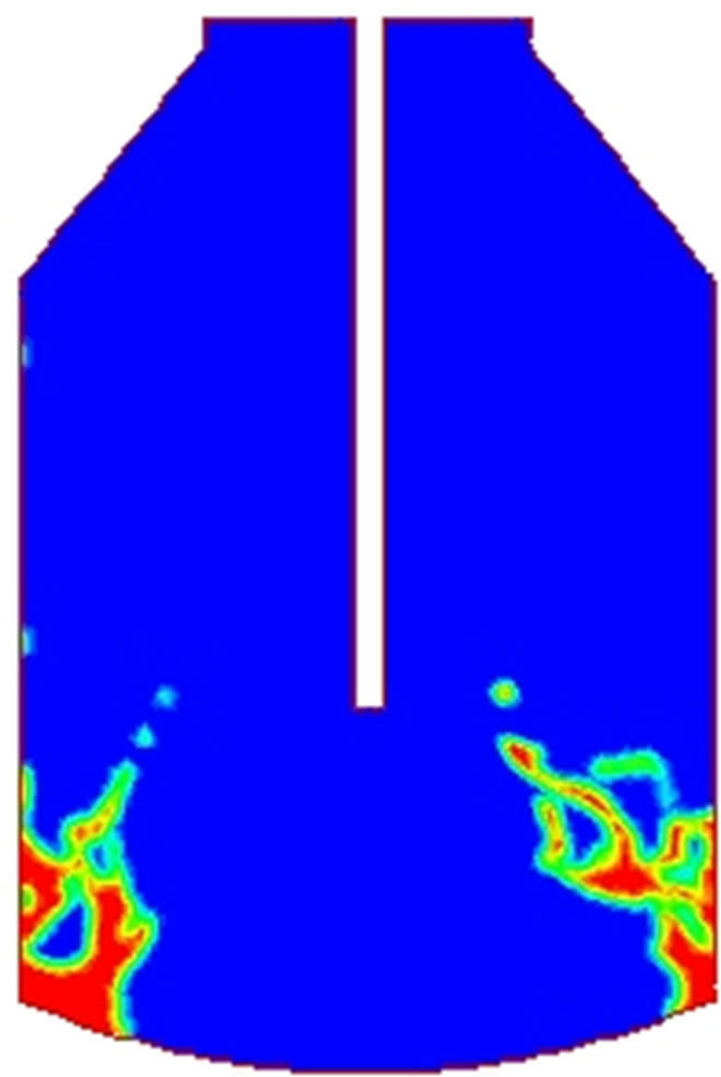 (c)
(c)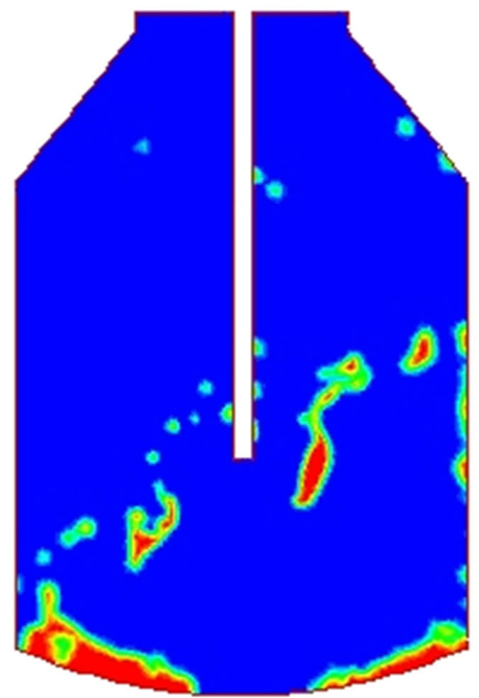 (d)
(d)
Figure 2. Evolution of slag splashing for a viscosity value of 0.4 kg∙m−2∙s−1. (a) 0.5 s; (b) 1.0 s; (c) 1.5 s; (d) 2.0 s.
 (a)
(a)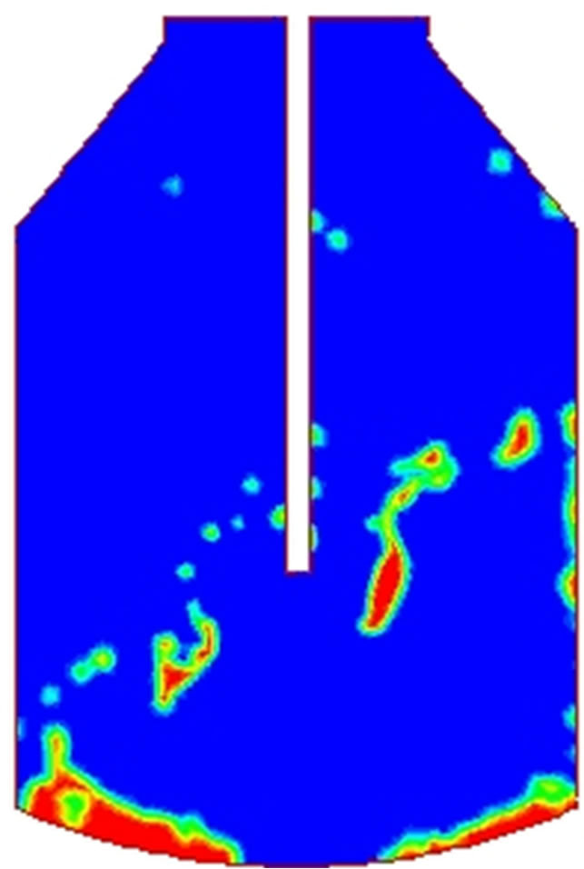 (b)
(b)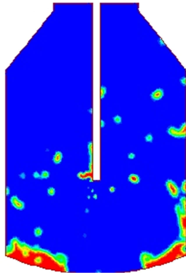 (c)
(c)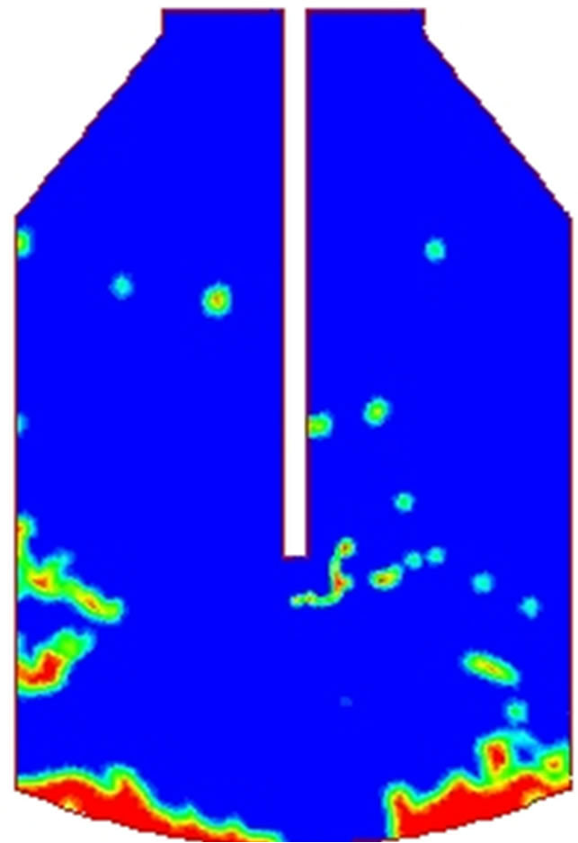 (d)
(d)
Figure 3. Distribution of phases in the furnace for t = 2 s for several values of viscosity. (a) 0.01; (b) 0.4; (c) 0.8; (d) 1.0 kg∙m−2∙s−1.
The average volume fraction of adhered molten slag to the furnace walls was calculated, and the results are shown in Figure 4. It is observed that as viscosity is in creased the average volume fraction of slag is decreased. This is due to the high shear forces required to form slag droplets and eject them to the furnace wall given that the jet momentum remains constant. These results show that the efficiency of the slag splashing process decreases as the molten slag viscosity is increased.
In accordance to Liu et al. [3], the following empirical expression relates the kinematic viscosity of slag and the lance height with the mass of slag splashed per unit area, A, in g∙m−2∙s:
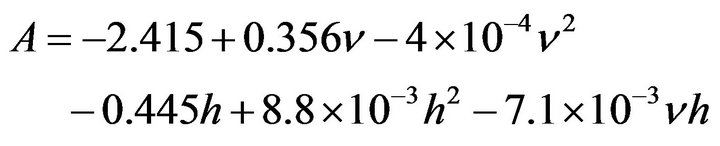 (6)
(6)
where  is the kinematic viscosity of slag expressed in 10−6 m2∙s−1 and h is the lance height in millimeters. Using Equation (6), Figure 5 depicts the influence of viscosity on the mass of slag splashed for lance height of 2000 mm and slag density of 2500 kg∙m−3. In this Figure one can see that, in accordance with the expression of Liu et al., the splashing rate decreases as viscosity is increased. These results are in agreement with those shown in Figure 4, corroborating in this way the numerical results of this work which yield that the slag splashing process efficiency is increased as viscosity of molten slag is decreased.
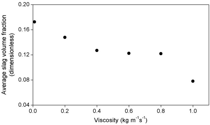
Figure 4. Average volume fraction of molten slag on the furnace walls.
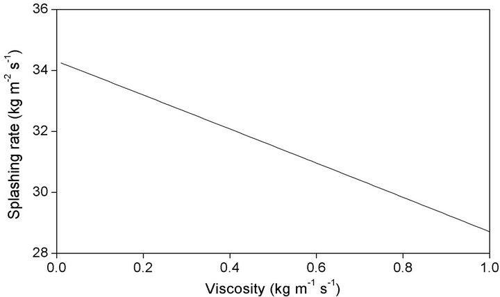
Figure 5. Splashing rate of molten slag (kg∙m−2∙s−1) as function of slag viscosity, in accordance with the empirical expression of Liu et al. [3].
4. Conclusion
Influence of molten slag viscosity on the efficiency of the slag splashing process was studied by means of Computational Fluid Dynamics simulations. Results of computer simulations are compared with results of an empirical expression reported in the literature, and qualitative agreement is found. The final conclusions are as follows: The splashing mechanism is strongly dependent on the molten slag viscosity. Ejection mechanism due to droplets formation becomes dominant as viscosity is decreased. On the contrary, washing mechanism due to bulk movement of molten slag becomes dominant as viscosity is increased. Efficiency of the slag splashing process, expressed in terms of the average volume fraction of molten slag in the converter walls, increases as slag viscosity is decreased. From an operational point of view, the splashing process must be carried out using low viscosity slag.
REFERENCES
- C. J. Messina and J. R. Paules. “The Worldwide Status of BOF Slag Splashing Practices and Performance,” Steelmaking Conference Proceedings, Pittsburgh, 1996, pp. 153-155.
- K. M. Goodson, N. Donaghy and R. O. Russell, “Furnace Refractory Maintenance and Slag Splashing,” Iron and Steelmaker, Vol. 22, No. 6, 1995, pp. 31-34.
- K. C. Mills, Y. Su, A. B. Fox, Z. Li, R. P. Thackray and H. T. Tsai, “A Review of Slag Splashing,” ISIJ International, Vol. 45, No. 5, 2005, pp. 619-633. doi:10.2355/isijinternational.45.619
- M. A. Barron and I. Hilerio, “Numerical Analysis of Slag Splashing in a Steelmaking Converter,” Computer Technology and Application, Vol. 2, No. 9, 2011, pp. 828-834.
- T. R. Galiullin, E. V. Protopopov, V. V. Sokolov and A. G. Chernyatevich, “Gas-Jet Conditions in the Slag Coating of Oxygen-Converter Linings,” Steel in Translation, Vol. 38, No. 2, 2008, pp. 97-100. doi:10.3103/S0967091208020010
- K. D. Peaslee, “Physical Modelling of Slag Splashing in the BOF,” Iron and Steel Engineer, Vol. 73, 1996, pp. 33- 37.
- M. J. Luomala, T. M. J. Fabritius, E. O. Virtanen, T. P. Siivola, T. L. J. Fabritius, H. Tenkku and J. J. Härkki, “Physical Model Study of Selective Slag Splashing in the BOF,” ISIJ International, Vol. 42, No. 11, 2002, pp. 1219-1224. doi:10.2355/isijinternational.42.1219
- K. D. Peaslee and W. Chen, “Important Factors for Effective Slag Splashing,” CIM Conference Proceedings, Edmonton, 2004.
- O. Olivares, A. Elias, R. Sanchez, M. Diaz-Cruz and R. D. Morales, “Physical and Mathematical Models of Gas-Liquid Fluid Dynamics in LD Converters,” Steel Research, Vol. 73, 2002, pp. 44-51.
- N. Standish and Q. L. He, “Drop Generation due to an Impinging Jet and the Effect of Bottom Blowing in the Steelmaking Vessel,” ISIJ International, Vol. 29, No. 6, 1989, pp. 455-461. doi:10.2355/isijinternational.29.455
- Q. L. He and N. Standish, “A Model Study of Droplet Generation in the BOF Steelmaking,” ISIJ International, Vol. 30, No. 4, 1990, pp. 305-309. doi:10.2355/isijinternational.30.305
- R. B. Bird, W. E. Stewart and E. N. Lightfoot, “Transport Phenomena,” 2nd Edition, Wiley, New York, 2002.
- B. G. Thomas, Q. Yuan, S. Sivaramakrishnan, T. Shi, S. P. Vanka and M. B. Assar, “Comparison of Four Methods to Evaluate Fluid Velocities in a Continuous Slab Casting Mold,” ISIJ International, Vol. 41, No. 10, 2001, pp. 1262-1271. doi:10.2355/isijinternational.41.1262
- M. Thomadakis and M. Leschziner, “A Pressure-Correction Method for the Solution of Incompressible Viscous Flows on Unstructured Grids,” International Journal for Numerical Methods in Fluids, Vol. 22, No. 7, 1996, pp. 581-601. doi:10.1002/(SICI)1097-0363(19960415)22:7<581::AID-FLD365>3.0.CO;2-R
- C. W. Hirt and B. D. Nichols, “Volume of Fluid (VOF) Method for the Dynamics of Free Boundaries,” Journal of Computational Physics, Vol. 39, No. 1, 1981, pp. 201- 225.