Natural Resources
Vol.3 No.1(2012), Article ID:18185,11 pages DOI:10.4236/nr.2012.31004
Comparison of Design and Analysis of Concrete Gravity Dam
![]()
Department of Civil Engineering, Chittagong University of Engineering & Technology, Chittagong, Bangladesh.
Email: *pdrmhali@yahoo.com, *md_hazrat_ali@cuet.ac.bd
Received August 30th, 2011; revised October 8th, 2011; accepted October 15th, 2011
Keywords: Comparison; Concrete Gravity Dam; Dam Failure; Design; Earthquake Intensity Perturbation; Stability and Stress
ABSTRACT
Gravity dams are solid concrete structures that maintain their stability against design loads from the geometric shape, mass and strength of the concrete. The purposes of dam construction may include navigation, flood damage reduction, hydroelectric power generation, fish and wildlife enhancement, water quality, water supply, and recreation. The design and evaluation of concrete gravity dam for earthquake loading must be based on appropriate criteria that reflect both the desired level of safety and the choice of the design and evaluation procedures. In Bangladesh, the entire country is divided into 3 seismic zones, depending upon the severity of the earthquake intensity. Thus, the main aim of this study is to design high concrete gravity dams based on the U.S.B.R. recommendations in seismic zone II of Bangladesh, for varying horizontal earthquake intensities from 0.10 g - 0.30 g with 0.05 g increment to take into account the uncertainty and severity of earthquake intensities and constant other design loads, and to analyze its stability and stress conditions using analytical 2D gravity method and finite element method. The results of the horizontal earthquake intensity perturbation suggest that the stabilizing moments are found to decrease significantly with the increment of horizontal earthquake intensity while dealing with the U.S.B.R. recommended initial dam section, indicating endanger to the dam stability, thus larger dam section is provided to increase the stabilizing moments and to make it safe against failure. The vertical, principal and shear stresses obtained using ANSYS 5.4 analyses are compared with those obtained using 2D gravity method and found less compares to 2D gravity method, except the principal stresses at the toe of the gravity dam for 0.10 g - 0.15 g. Although, it seems apparently that smaller dam section may be sufficient for stress analyses using ANSYS 5.4, it would not be possible to achieve the required factors of safety with smaller dam section. It is observed during stability analyses that the factor of safety against sliding is satisfied at last than other factors of safety, resulting huge dam section to make it safe against sliding. Thus, it can be concluded that it would not be feasible to construct a concrete gravity dam for horizontal earthquake intensity greater than 0.30 g without changing other loads and or dimension of the dam and keeping provision for drainage gallery to reduce the uplift pressure significantly.
1. Introduction
Basically, a gravity concrete dam is defined as a structure, which is designed in such a way that its own weight resists the external forces. It is primarily the weight of a gravity dam which prevents it from being overturned when subjected to the thrust of impounded water [1]. This type of structure is durable, and requires very little maintenance. Gravity dams typically consist of a nonoverflow section(s) and an overflow section or spillway. The two general concrete construction methods for concrete gravity dams are conventional placed mass concrete and RCC. Gravity dams, constructed in stone masonry, were built even in ancient times, most often in Egypt, Greece, and the Roman Empire [2,3].
However, concrete gravity dams are preferred these days and mostly constructed. They can be constructed with ease on any dam site, where there exists a natural foundation strong enough to bear the enormous weight of the dam. Such a dam is generally straight in plan, although sometimes, it may be slightly curve. The line of the upstream face of the dam or the line of the crown of the dam if the upstream face in sloping, is taken as the reference line for layout purposes, etc. and is known as the “Base line of the Dam” or the “Axis of the Dam”. When suitable conditions are available, such dams can be constructed up to great heights. The ratio of base width to height of high gravity dams is generally less than 1:1.
A typical cross-section of a high concrete gravity dam
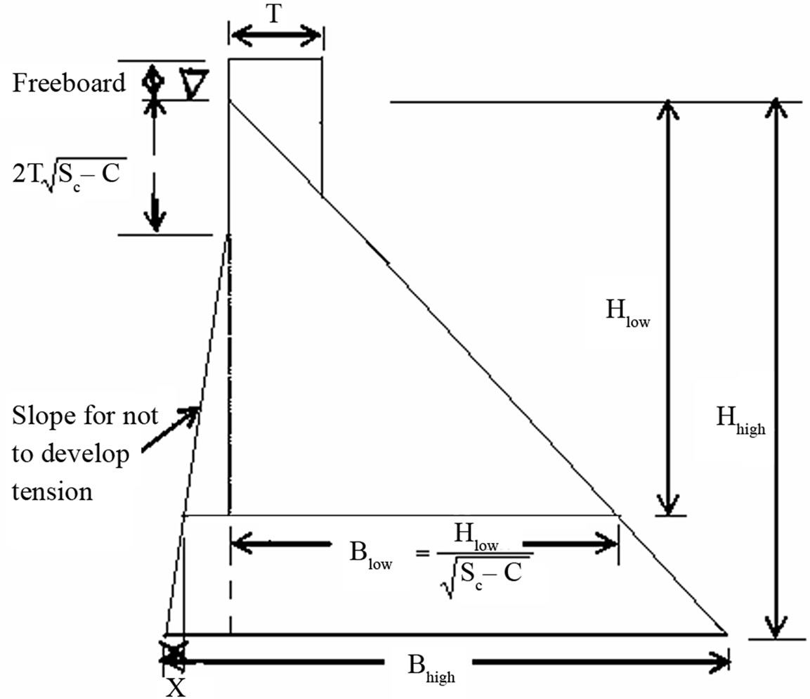
Figure 1. Typical section of a high concrete gravity dam.
is shown in Figure 1. The upstream face may be kept throughout vertical or partly slanting for some of its length. A drainage gallery is generally provided in order to relieve the uplift pressure exerted by the seeping water. Purposes applicable to dam construction may include navigation, flood damage reduction, hydroelectric power generation, fish and wildlife enhancement, water quality, water supply, and recreation.
Many concrete gravity dams have been in service for over 50 years, and over this period important advances in the methodologies for evaluation of natural phenomena hazards have caused the design-basis events for these dams to be revised upwards. Older existing dams may fail to meet revised safety criteria and structural rehabilitation to meet such criteria may be costly and difficult. The identified causes of failure, based on a study of over 1600 dams [4] are: Foundation problems (40%), Inadequate spillway (23%), Poor construction (12%), Uneven settlement (10%), High poor pressure (5%), Acts of war (3%), Embankment slips (2%), Defective materials (2%), Incorrect operation (2%), and Earthquakes (1%). Other surveys of dam failure have been cited by [5], who estimated failure rates from 2 ´ 10–4 to 7 ´ 10–4 per damyear based on these surveys.
2. Loads
In the design of gravity concrete, it is essential to determine the loads required in the stability and stress analyses. The forces which may affect the design are: 1) Dead load or stabilizing force; 2) Headwater and tailwater pressures; 3) Uplift; 4) Temperature; 5) Earth and silt pressures; 6) Ice pressure; 7) Earthquake forces; 8) Wind pressure; 9) Subatmospheric pressure; 10) Wave pressure, and 11) Reaction of foundation.
The seismic safety of such dams has been a serious concern since damage to the Koyna Dam in India in 1967 which has been regarded as a watershed event in the development of seismic analysis and design of concrete gravity dams all over the world. It is essential that those responsible must implement policies and procedures to ensure seismic safety of dams through sound professional practices and state-of-the-art in related technical areas. Seismic safety of dams concerns public safety and therefore demands a higher degree of public confidence. The estimations and descriptions of various forces are provided briefly in the following sections.
2.1. Water Pressure
Water pressure (P) is the most major external force acting on gravity dams. The horizontal water pressure exerted by the weight of water stored on the upstream and downstream sides of the dam can be estimated from the rule of hydrostatic pressure distribution and can be expressed by
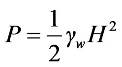 (1)
(1)
where, H is the depth of water and  is the unit weight of water.
2.2. Uplift Pressure
Water seepage through the pores, cracks and fissures of the foundation materials, and water seepage through dam body and then to the bottom through the joints between the body of the dam and its foundation at the base exert an uplift pressure on the base of the dam. According to the [6], the uplift pressure intensities at the heel and toe of the dam should be taken equal to their respective hydrostatic pressures and joined the intensity ordinates by a straight line. When drainage galleries are provided to relieve the uplift, the recommended uplift at the face of the gallery is equal to the hydrostatic pressure at toe plus 1/3rd of the difference between the hydrostatic pressures at the heel and the toe, respectively.
2.3. Earthquake Forces
An earthquake produces waves, which are capable of shaking the earth upon which the gravity dams rest, in every possible direction. The effect of an earthquake is, therefore, equivalent to imparting acceleration to the foundations of the dams in the direction in which the wave is traveling at the moment.
Generally, an earthquake induces horizontal acceleration (ah) and vertical acceleration (av). The values of these accelerations are generally expressed as percentage of the acceleration due to gravity (g), i.e., a = 0.10 g or 0.20 g, etc. On an average, a value of a equal to 0.10 to 0.15 g is generally sufficient for high dams in seismic zones. In extremely seismic regions and in conservative designs, even a value up to 0.30 g may sometimes be adopted [7].
Earthquake loadings should be checked for horizontal as well as vertical earthquake accelerations. While earthquake acceleration might take place in any direction, the analysis should be performed for the most unfavorable direction.
The earthquake loadings used in the design of concrete gravity dams are based on design earthquakes and sitespecific motions determined from seismological evaluation. At a minimum, a seismological evaluation should be performed on all projects located in seismic zones 1, 2, and 3 of Bangladesh [8], depending upon the severity of earthquakes.
The seismic coefficient method of analysis should be used in determining the resultant location and sliding stability of dams. In strong seismicity areas, a dynamic seismic analysis is required for the internal stress analysis.
2.3.1. Effect of Vertical Acceleration ((v)
A vertical acceleration may either act downward or upward. When it acts in the upward direction, then the foundation of the dam will be lifted upward and becomes closer to the body of the dam, and thus the effective weight of the dam will increase and hence, the stress developed will increase.
When the vertical acceleration acts downward, the foundation shall try to move downward away from the dam body; thus, reducing the effective weight and the stability of the dam, and hence is the worst case for design. The net effective weight of the dam is given by
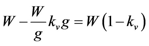 (2)
(2)
where, W is the total weight of the dam, kv is the fraction of gravity adopted for vertical acceleration, such as 0.10 or 0.20, etc.
In other words, vertical acceleration reduces the unit weight of the dam material and that of water to (1 – kv) times their original unit weights.
2.3.2. Effects of Horizontal Acceleration ((h)
The horizontal acceleration may cause 1) hydrodynamic pressure, and 2) horizontal inertia force.
1) Hydrodynamic Pressure: Horizontal acceleration acting towards the reservoir causes a momentary increase in the water pressure, as the foundation and dam accelerate towards the reservoir and the water resists the movement owing to its inertia. According to [9], the amount of this hydrodynamic force (Pe) is given by
 (3)
(3)
where, Cm = maximum value of pressure coefficient for a given constant slope =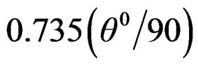 , where q is the angle in degree, which the upstream face of the dam makes with the horizontal; kh = fraction of gravity adopted for horizontal acceleration (ah) such as
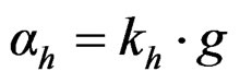 .
.
The moment of this force about the base is given by
 (4)
(4)
2) Horizontal Inertia Force: In addition to exerting the hydrodynamic pressure, the horizontal acceleration produces an inertia force into the body of the dam. This force is generated to keep the body and the foundation of the dam together as one piece. The direction of the produced force will be opposite to the acceleration imparted by the earthquake.
Since an earthquake may impart either upstream or downstream acceleration, it is needed to choose the direction of this force in the stability analysis of dam structure in such a way that it produces most unfavorable effects under the considered conditions. For example, when the reservoir is full, this force will produce worst results if it is additive to the hydrostatic water pressure, thus acting towards the downstream (i.e., when upstream earthquake acceleration towards the reservoir is produced). When the reservoir is empty, this force would produce worst results, if considered to be acting upstream (i.e., when earthquake acceleration moving towards the downstream is produced.
The horizontal inertia force is given by
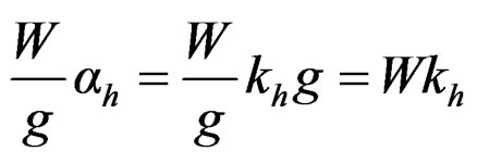 (5)
(5)
where, kh is the fraction of gravity adopted for horizontal acceleration, such as 0.10 or 0.20, etc.
This force should be considered to be acting at the center of gravity of the mass, regardless of the shape of the cross-section, and it acts horizontally downstream in worst cases, i.e., for reservoir full case.
2.4. Silt Pressure
Generally, silt gets deposited at the upstream face of the dam. If h is the height of silt deposited, then the force exerted by this silt in addition to external water pressure, can be represented by Rankine’s formula as
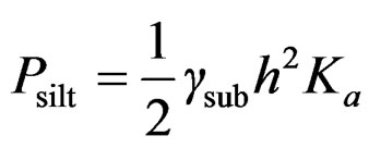 (6)
(6)
where, Ka is the coefficient of active earth pressure of silt =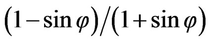 , where j is the angle of internal friction of soil (cohesion is neglected); and gsub is the submerged unit weight of silt material.
2.5. Wave Pressure
Waves are generated on the surface of the reservoir by the blowing winds, ships, etc., which cause a pressure towards the downstream side. Wave pressure depends upon the wave height (hw) and the total force due to wave action (Pw) can be expressed as
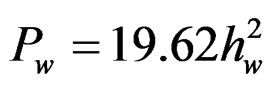 (7)
(7)
This force acts at a distance  below the reservoir surface.
2.6. Ice Pressure
The ice which may be formed on the water surface of the reservoir in cold countries may sometimes melt and expand. The dam face has then to resist the thrust exerted by the expanding ice. This force acts linearly along the length of the dam and at the reservoir level. Estimates of the thrust force vary according to the anticipated ice thickness, and range from 2.4 ´ 105 to 14.4 ´ 105 N/m2 of contact with the vertical face of the dam [10]. On an average, a value of 500 kN/m2 may be allowed for ordinary conditions.
2.7. Weight of the Dam
The weight of the dam body and its foundation is the major resisting force. In two dimensional analysis of a gravity dam, the cross-section can be divided into rectangles and triangles. The resultant of all the downward forces will represent the total weight of the dam acting at the center of gravity of the dam.
3. Profile of a Dam from Practical Considerations
The elementary profile of a gravity dam (i.e., triangle with maximum water surface at apex) is only a theoretical profile. Certain changes will have to be made in this profile in order to cater to the practical needs. These needs are: 1) providing a straight top width for a road construction over the top of the dam, and 2) providing a free-board above the top water surface so that water may not spill over the top of the dam due to wave action, etc.
1) Top Width: The top width (T) of the high dam should be sufficient to provide carriage-way and to withstand earthquake shocks and wave actions, and this may be selected like large earthen dam as
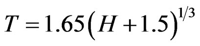 (8)
(8)
The most economical top width without considering earthquake forces varies between 6 and 10 m and is generally taken approximately equal to .
.
2) Freeboard: Nowadays a freeboard equal to 4% - 5% of the dam height is provided. The section of gravity dam should be chosen in such a way that it is the most economic section and satisfies all the conditions and requirements of stability. Hence, after the section of the dam has been arrived at, the stability analysis for the dam must be carried out.
4. Low and High Concrete Gravity Dams
The height of the dam to be constructed should be checked to ensure whether it is a low gravity dam or a high gravity dam. If the height of the dam is less than that given by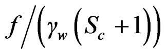 , where f is the permissible compressive stress of the dam material; Sc is the specific gravity of the dam material; then the dam will be a low gravity dam, otherwise it will be a high gravity dam (Figure 1).
When the height of the dam exceeds the height of the low gravity dam (i.e., high dam), the upper height equal to low gravity dam can be designed as low gravity dam and its remaining height can be designed as follows [7]:
The total base width required for high gravity dam can be given by
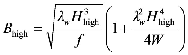 (9)
(9)
and the increase in length at u/s face of high gravity dam can be determined by
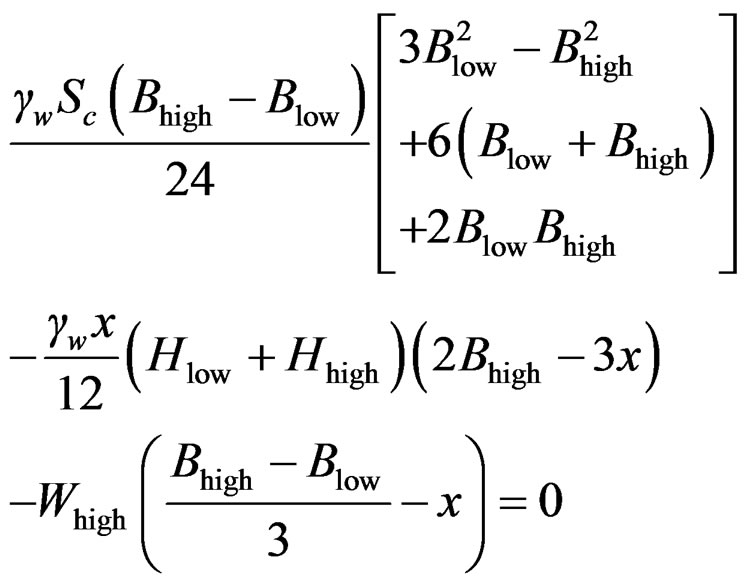 (10)
(10)
where, W is the total weight of dam portion and water above the base of the high dam, Blow is the base width of low gravity dam, Hhigh is the base width of high gravity dam, x is the increment of length at u/s face, Hlow is the height of maximum water level above the base of low gravity dam, Hhigh is the height of maximum water level above the base of high gravity dam, and Whigh is the total weight of dam portion and water above the base of high gravity dam.
5. Design Criteria
The design and evaluation of hydraulic structures for earthquake loading must be based on appropriate criteria that reflect both the desired level of safety and the choice of the design and evaluation procedures. The first requirement is to establish design earthquake ground motions to be used as the seismic input by giving due consideration to the consequences of failure and the designated operational function. Then the response of the structure to this seismic input must be calculated taking into account the significant interactions with the rock, soil, or pile foundation as well as with the impounded, or surrounding and contained water. The analysis should be formulated using a realistic idealization of the structure-water-foundation system, and the results are evaluated in view of the limitations, assumptions, and uncertainties associated with the seismic input and the method of analysis.
The design of a gravity dam should be checked for two cases, i.e., 1) Reservoir Full Case, and 2) Reservoir Empty Case. When the reservoir is full, the major forces acting are: weight of the dam, external water pressure, uplift pressure, and earthquake forces in serious seismic zones. The minor forces are: silt pressure, ice pressure in cold countries and wave pressure. For the most conservative design and from purely theoretical point of view, a situation may arise when all the forces may act together. For reservoir empty case, empty reservoir with a horizontal earthquake force produced towards the u/s has to be checked for non-development of tension at toe. In this study, water pressure due to maximum pool level, extreme uplift pressure without any reduction due to drainage, tailwater pressure up to a certain height, and earthquake forces, will be considered in the design of gravity dam.
6. Modes of Failures and Structural Stability of Gravity Dams
A gravity dam may fail due to 1) overturning/rotation about the toe; 2) crushing; 3) development of tension, causing ultimate failure by crushing; and 4) shear failure called sliding.
1) Overturning/Rotation about the Toe: If the resultant of all the forces acting on a dam at any of its sections passes outside the toe, the dam shall rotate and overturn about the toe. The factor of safety against overturning (F.S.O.) generally varies from 1.5 to 2.
2) Compression or Crushing: A dam may fail by the failure of its materials, i.e., the compressive stresses produced may exceed the allowable stresses, and the dam material may get crushed. The vertical direct stress distribution at the base is given by
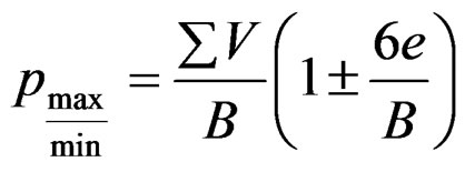 (11)
(11)
where, e is the eccentricity of the resultant force from the center of the base, the maximum value of which can be permitted on either side of the center of the base is equal to B/6; SV is the total vertical force; and B is the base width of the dam.
3) Tension: Masonry and concrete gravity dams are usually designed in such a way that no tension is developed anywhere, because these materials cannot withstand sustained tensile stresses. For achieving economy in designs of very high gravity dams, certain amount of tension may be permitted under severest loading condition. The maximum permissible tensile stress for high concrete gravity dams, under worst loadings, may be taken as 500 kN/m2.
4) Sliding: Stability against sliding and shearing through a certain section through the dam across the foundation or along cracks in the foundation is of utmost importance. That is why it needs to be examined with special attention [11,12]. Sliding or shear failure will occur when the net horizontal force above any plane in the dam or at the base of the dam exceeds the frictional resistance developed at that level. The factor of safety against sliding (F.S.S.) is given by
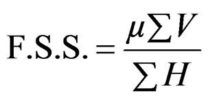 (12)
(12)
where, mSV is the shear resistance in which SV is the total vertical forces; m is the coefficient of friction between the dam base and foundation, which varies from 0.65 - 0.75; and SH is the total external horizontal forces.
In low dams, the safety against sliding should be checked only for friction, but in high gravity dams, for economic precise designs, the shear strength of the joint, which is an additional shear resistance, must also be considered. If this shear resistance of the joint is considered, then the equation for factor of safety against sliding which is measured by shear friction factor (S.F.F.) becomes
 (13)
(13)
where, q is the average shear strength of the joint which varies from about 1400 kN/m2 for poor rocks to about 4000 kN/m2 for good rocks.
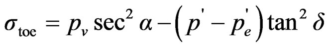
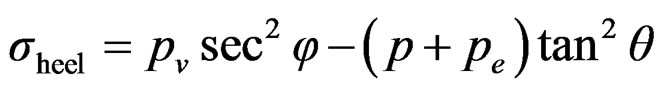
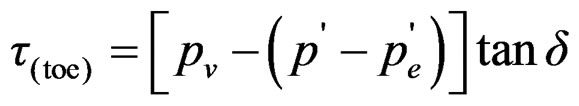
6.1. Principal and Shear Stresses
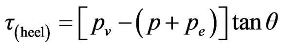
The vertical stress intensity, pmax or pmin determined using Equation (11) is not the maximum direct stress produced anywhere in the dam. The maximum normal stress will, indeed, be the major principal stress that will be generated on the major principal plane. The principal (s ) and shear (t ) stresses at the toe and heel of gravity dam can be expressed [7] by
 (14)
(14)
 (15)
(15)
 (16)
(16)
 (17)
(17)
where, δ is the angle which the downstream face of the dam makes with the vertical, θ is the angle which the upstream face makes with the vertical, pv is the intensity of uplift pressure, p is the minor principal stress at the heel, pe is the hydrodynamic pressure exerted by the head water, and  is the hydrodynamic pressure exerted by the tailwater during an earthquake.
In a gravity dam, stability is secured by making it of such a size and shape that it will resist overturning, sliding and crushing at the toe. The dam will not overturn provided that the moment around the turning point, caused by the water pressure is smaller than the moment caused by the weight of the dam. This is the case if the resultant force of water pressure and weight falls within the base of the dam. However, in order to prevent tensile stress at the upstream face and excessive compressive stress at the downstream face, the dam cross section is usually designed so that the resultant falls within the middle at all elevations of the cross section (the core). For this type of dam, impervious foundations with high bearing strength are essential.
6.2. Stability Analysis
The stability of a gravity dam can be approximately and easily analyzed by two dimensional gravity method and three dimensional methods such as slab analogy method, trial load twist method, Finite Element Method (FEM), or by experimental studies on models. In this study, the stability of the dam will be analyzed by two dimensional gravity method and Finite Element Method (FEM), using ANSYS 5.4.
The steps involved in the analysis of gravity dam by analytical two dimensional gravity method are: 1) consider unit length of the dam; 2) work out the magnitude and directions of all the vertical and horizontal forces acting on the dam and their algebraic sum; 3) determine the moment arm of all these forces about the toe; 4) determine the moments of all these about the toe and find out the algebraic sum of all those moments; 5) find out the location of the resultant force by determining its distance from the toe; 6) find out the eccentricity of the resultant, which must be less than B/6 in order to ensure that no tension is developed anywhere in the dam; 7) determine the vertical stresses at the toe and heel; 8) determine the maximum normal stresses at the toe and heel; and 9) determine the factor of safety against overturning, sliding and crushing. The assumptions made in the two dimensional gravity method are: 1) the dam is considered to be composed of a number of cantilevers, each of which is 1 m thick and acts independent of the other; 2) no loads are transferred to the abutments by beam action; 3) the foundation and the dam behave as a single unit; 4) the materials in the dam body and foundation are isotropic and homogeneous; and 5) the stresses developed in the dam and foundation are within elastic limits and no movement of the foundation is caused due to transference of loads.
The finite element method (FEM) is a numerical method for determining responses (deformation, strain, stress, etc.) of a body under external loads. The finite-element method (FEM) uses a concept of “piecewise approximation”. In theory, the elements can be of different shapes and sizes. Until developing FEM it was almost difficult to calculate point to point responses (approximately) of a body of any geometric shape and any complex type of loading conditions. In this method, the entire dam body is divided by using equivalent system of small triangular element for obtaining responses within and boundary (node) of the element. This method determines first the global deformations at the nodes of the element then determines successively other responses such as strains, stresses, etc. Nowadays, this method is available as a commercial FE programming or software (ABAQUS, ANSYS, STADD.pro, SAP, etc.) for solving large problems. Most of the FE programming used for either general purpose or special purpose follows the same basic procedure of finite element method.
7. Results and Discussion
The section of gravity dam should be chosen in such a way that it is the most economic section and satisfies all the conditions and requirements of stability. Hence, after a design section of the dam has been arrived at, the stability analysis for the dam must be carried out. In this study, water pressure due to maximum pool level, extreme uplift pressure without any reduction due to drainage, tailwater pressure up to 6 m height (reservoir full case), and earthquake forces are considered in the design of gravity dam. The earthquake forces can be taken as equivalent to 0.15 g for horizontal forces and 0.10 g for vertical forces, considering the earthquake might occur in seismic zone 2 of Bangladesh. The uplift is considered as equal to the hydrostatic pressure at either ends. The unit weights of concrete and water are assumed to be 24.00 kN/m3 and 9.81 kN/m3, respectively. Assuming allowable concrete compressive strength of 3000 kN/m2, the limiting height of low gravity dam is calculated to be 90 m. Thus, in order to consider the dam as high dam, the preliminary height of the high dam is increased to 95 m. A freeboard of 5 m equals to about 4% - 5% of the dam height is considered. Finally, the total height of the dam including freeboard is considered to be 100 m for stability and stress analyses. The u/s face is flattened to keep developed tension at the toe within allowable limit. For stability and stress analyses, the resulting high concrete gravity dam with design external forces is shown in Figure 2.
The stability analyses are performed for horizontal earthquake intensities varying from 0.10 g - 0.30 g with 0.05 g increment, keeping the vertical earthquake intensity constant at 0.10 g and unchanging other loads which may
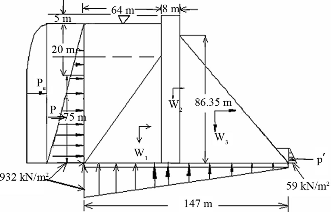
Figure 2. High concrete gravity dam with external forces.
likely to occur in Bangladesh. For example, the stability and stress analyses are described in the following paragraph in the case of 0.15 g horizontal earthquake intensity and other constant design loads (i.e., the main case for which the dam to be constructed in seismic zone 2 of Bangladesh).
The total vertical and horizontal forces are calculated and the moments of all the forces about toe of the dam are taken. The value of eccentricity is found to be 20.04 m, which is less than B/6, i.e., 24.5 m, and hence, no tension will be developed in any portion of the dam. The vertical stress pv at toe of the dam is found to be 1267.36 kN/m2, which is less than allowable concrete compressive stress of 3000 kN/m2; and 126.92 kN/m2 at heel, which is less than the allowable concrete tensile stress of 500 kN/m2. The principal stress at toe s (toe) is found to be 2178.93 kN/m2, which is less than 3000 kN/m2; and –412.75 kN/m2 at heel s (heel), which is less than 500 kN/m2. Neglecting small hydrodynamic pressure exerted by the tailwater (Negligence is on the safer side), the shear stresses t at toe and heel are found to be 1049.53 kN/m2 and 632.42 kN/m2, respectively, which are less than 3000 kN/m2. All the stresses calculated at toe and heal of the dam are found to satisfy the conditions of safe design. The factors of safety against overturning and sliding, and shear friction factor are found to be 1.53, 1.001, and 3.87, respectively, which are greater than 1.5, 1.0, and 3.0, respectively, indicating the design is safe against these failures. An average value of the frictional coefficient, m = 0.7 (0.65 – 0.75) is considered to calculate the factor of safety against sliding and shear friction factor. For the set of loading conditions shown in Figure 2 and for economic dam section, the u/s face of the dam can be flatten up to a slope of 64H:75V in order to make it safe, but it cannot be flatten more than 64H:75V slope because the principal stress at the heel will be more than the allowable limit of 500 kN/m2. If it is not possible to provide safe design by flattening the u/s face, either the top width of the dam or the d/s slope of the dam needs to be enlarged, but from economic and stability points of view, it is not feasible to widen the top width of the dam. The results for varying horizontal earthquake intensities, keeping other loads unchanged, are summarized in Table 1.
A static finite element analysis was also carried out with the same dam section and loading conditions used in 2D gravity method to investigate the stresses and deformations under the expected design loads. To simulate the process of activity of concrete gravity dam under given loading conditions, the assumptions made in the finite element analysis are: 1) the dam materials are homogeneous and isotropic; 2) since the nature of loading on the dam makes the dam problem as plain strain problem, therefore, it is analyzed as a plane strain problem; 3) the modulus of elasticity and Poisson's ratio were taken as 8.3 GPa [the modulus of elasticity was calculated based on supplied empirical formula 57500× [13] and it was found 8.3 GPa for
  = 3000 kN/m2] and 0.18 (Poisson’s ratio for plain concrete generally varies from 0.15 - 0.20), respectively; and 4) no vertical and horizontal displacements are assumed to be occurred due to applied loads.
The finite element analysis was carried out using general purpose finite element software (ANSYS 5.4) for linear elastic analysis of concrete gravity dam. ANSYS FE programming consists of preprocessor, solution, and post processor parts. The FE modeling of a body is carried out in preprocessing part and post processing procedure is used to generate and interpret results. Six-noded quadratic triangular plane strain solid elements were used to discretize the entire gravity dam to achieve more accurate results. All nodes of elements have two degrees of freedom. The integration points in the case of reduced integration are 3 for six-noded quadratic triangular plane strain solid element.
The entire gravity dam was divided as three regular shaped parts for calculating self weight of the dam. The self weight of each part was assumed to act at its own center of gravity. The other loads, such as, weight and pressure of water at the u/s and d/s sides of the dam, hydrodynamic pressures of water at the u/s and d/s sides and uplift pressure of water at the bottom of the dam were applied as surface loads on the element’s side. The horizontal earthquake intensities were perturbed from 0.10 g - 0.30 g with 0.05 g increment, keeping other loads unchanged. The horizontal earthquake loading of different intensities and vertical earthquake loading were applied at the point of self load of each part of the dam.
A post processing procedure was used to generate results directly from ANSYS 5.4 finite element program. This program determines displacements at global coordinates and strains and stresses at local –x and –y coordinate systems as well as it can automatically determine the principal stresses. For example, the contour plot of shear stress (t) in the case of horizontal earthquake intensity of 0.15 g is shown in Figure 3.
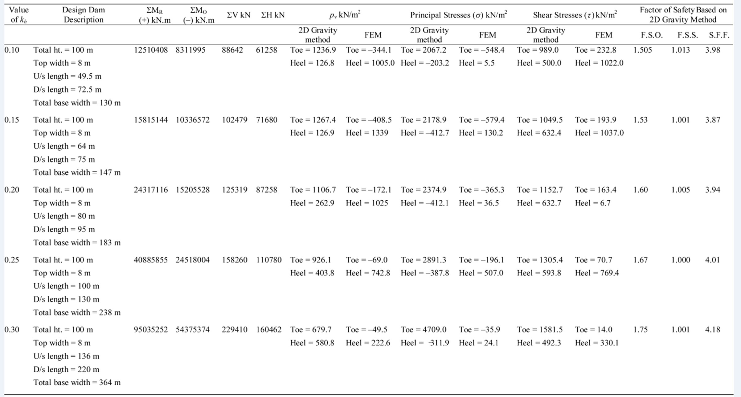
Table 1. Comparsion of stresses obtained from 2D Gravity and FE methods and factors of safety based on 2D gravity method for varying Kh
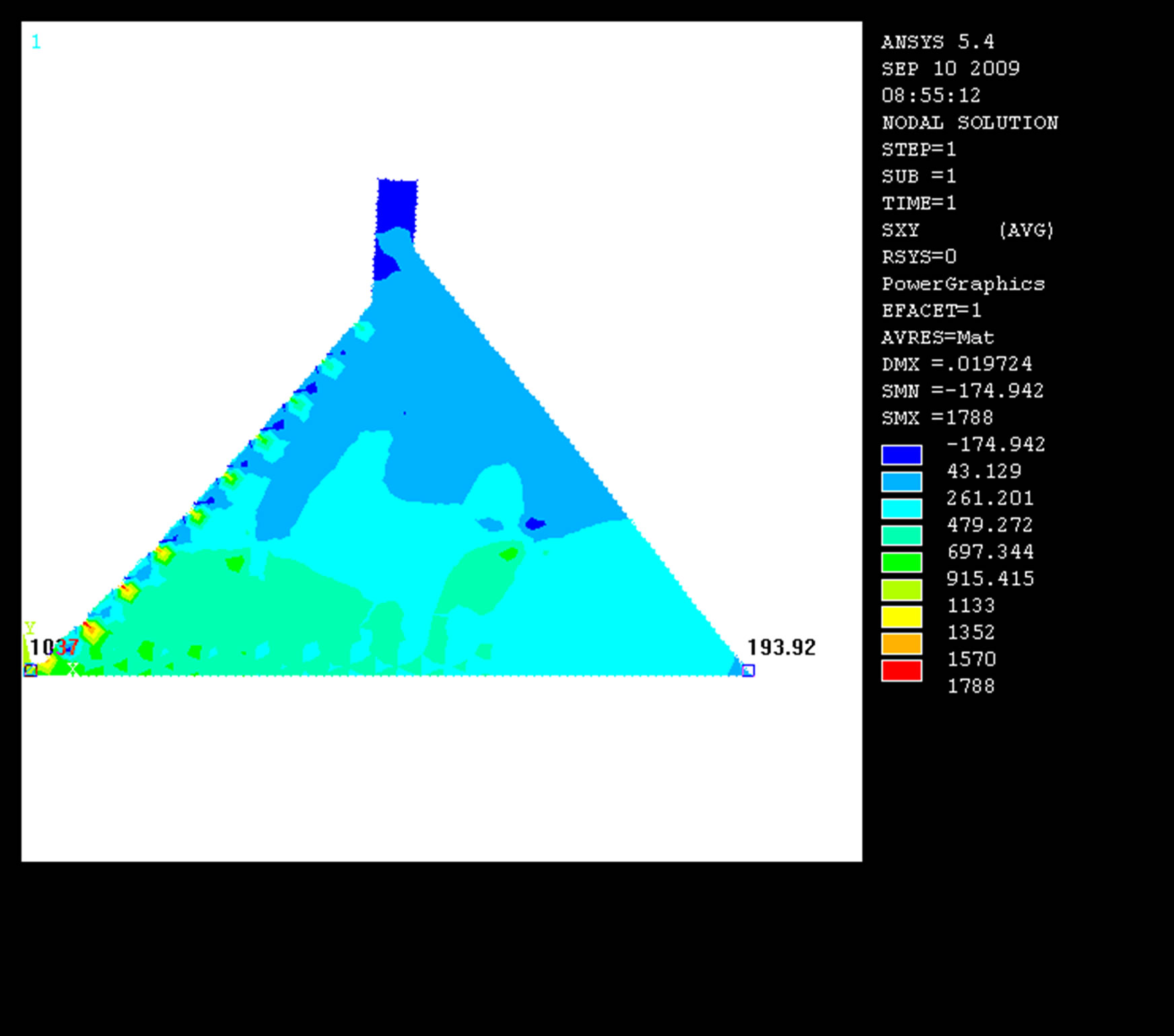
Figure 3. Contour plot of shear stress (t).
The variation of shear stress in the dam body can also be found with different color codes (Figure 3). The vertical, principal and shear stresses obtained using finite element analysis for varying horizontal earthquake intensities from 0.10 g - 0.30 g with 0.05g increment were compared with those obtained from the analytical 2D gravity method as shown in Table 1. Table 1 shows that for each intensity of horizontal earthquake acceleration the vertical stresses pv obtained from ANSYS 5.4 vary significantly from the stresses obtained using analytical 2D gravity method; because the vertical stresses in the case of ANSYS 5.4 were found always negative at the toe, whereas no negative values were found using 2D gravity method. However, the vertical stresses found at the toe and heel of the dam for 0.10 g - 0.30 g using these two methods respectively are within the concrete allowable compressive stress. Similarly, the principal and shear stresses at the toe and heel obtained from ANSYS are also found to vary significantly with those obtained from the 2D gravity method (Table 1). The principal stresses at the toe of the dam were found to exceed the allowable concrete tensile stress slightly for 0.10 g - 0.15 g only. The principal stresses can be made safe by further flattening the u/s side of the dam, i.e., by further increasing the self weight of the dam. The shear stresses obtained using these two methods for 0.10 g - 0.30 g are found to satisfy the allowable concrete compressive stress successfully and ANSYS results are found to vary in similar fashion with those obtained using 2D gravity method, specifically at the toe of the dam (Table 1).
The vertical, principal and shear stresses found using ANSYS are more conservative than those obtained using 2D gravity method, except the principal stresses at the toe of the gravity dam for 0.10 g - 0.15 g. This significant variation of results could be happened, because in analytical procedure all surface loads are assumed to act as concentrated load at its own center of gravity and the determination of stresses at the toe and heel is based on average values, while in FE analysis it is the determination of point to point stresses of the entire dam under actual loading conditions and thus the FE analysis can be regarded much more reliable than any other methods. Only the principal stresses found at the toe of the dam using FE analyses for 0.10 g - 0.15 g and using 2D gravity method for 0.30 g were found to exceed the allowable concrete stress throughout the analyses. The principal stresses found at the toe of the dam using FE analyses for 0.10 g - 0.15 g can be made safer by just flattening the u/s face of the dam, but it might not be possible to make it safe in the case of 2D gravity method for 0.30 g. Moreover, it was very difficult to achieve the required factor of safety against sliding, specifically for 0.30 g horizontal earthquake intensity. Although, it suggests apparently that smaller dam section may be enough for stress analyses using FEM (Table 1), it would not possible to achieve the required factors of safety with smaller dam section. Thus, further dynamic analyses using this/other FE methods may be carried out to obtain more reliable information to make necessary comments on the stability of the dam.
The stabilizing moments are determined using analytical 2D method dealing with the U.S.B.R. recommended initial dam section and found to decrease significantly with the increment of horizontal earthquake intensity, indicating endanger to the dam stability, thus larger dam section is designed to increase the stabilizing moments and to make it safe against failure. The factors of safety against overturning and sliding, and shear friction factor were determined to examine whether these factors are safe against these failures. It is observed that the factor of safety against sliding is satisfied at last than other factors of safety, resulting huge dam section to make it safe against sliding and making impossible to provide at least 1:1 ratio of dam base width to dam height, using analytical 2D gravity method (Table 1).
Based on the 2D gravity method, the volume of concrete required per meter length of the gravity dam to make it safe against failure for varying horizontal earthquake intensities and unvarying other loads is found to increase exponentially as shown in Figure 4. During factor of safety determination, it is observed that the factor of safety against sliding is satisfied much later than other factors of safety, allocating huge dam section to make it safe against sliding. Therefore, sufficient base width, silt pressure, adequate strong rock foundation, drainage gallery to reduce uplift pressure, and construction joints to increase frictional resistance need to be ascertained to improve factor of safety against sliding as well as provisions should be made for shrinkage and temperature stresses. The shrinkage and temperature stresses will cause the concrete to crack unless remedial measures are undertaken [7]. These stresses may be avoided by using minimum amount of concrete, low lift of concrete (generally 1.5 m), construction joints, special low heat cement, and cooling aggregates and concrete surface, etc.
Initially, the section of the dam is selected arbitrarily based on the U.S.B.R. recommendations. This arbitrary selection of the gravity dam profile is much more complex than actual profile, because in actual profile at least the height and top width of the dam are fixed based on the requirements. Thus, the selection technique of the dam profile as well as the stability analysis procedures can be applied to the actual dam design. The detailed factors of safety and stresses analyses are described and comparison between the two methods has been made (Table 1). Finally, it may be concluded that it would not

Figure 4. Volume of concrete (m3) required per meter length of gravity dam for stability against varying horizontal earthquake intensity.
be feasible to construct a concrete gravity dam in seismic zone 2 of Bangladesh for kh values greater than 0.30 without changing other loads and/or dimension of the dam, and without keeping provision for drainage gallery to reduce the uplift pressure significantly at the base of the dam.
8. Conclusions
The section of gravity dam should be chosen in such a way that it is the most economic section and satisfies all the conditions and requirements of stability. The preliminary dam section is selected based on the U.S.B.R. recommendations, and the stability and stress conditions of the high concrete gravity dam are approximated and analyzed for varying horizontal earthquake intensity and unvarying other loads, using two-dimensional gravity method and finite element method. The horizontal earthquake intensities are perturbed from 0.10 g - 0.30 g with 0.05g increment, keeping other loads unchanged, to calculate the total horizontal and vertical forces and moments at the toe of the gravity dam, and to examine the stability and stress conditions of the dam using the two methods. Dealing with the U.S.B.R. recommended initial dam section, the stabilizing moments are found to decrease significantly with the increment of horizontal earthquake intensity, indicating endanger to the dam stability, thus larger dam section is designed to increase the stabilizing moments and to make it safe against failure. The results of the horizontal earthquake intensity perturbbation suggest that the stability of the gravity dam endangers with the increment of horizontal earthquake intensities unless the dam section is enlarged significantly. The FE analyses were carried out using the same dam section and loading conditions used in 2D gravity method. The vertical, principal and shear stresses using ANSYS 5.4 are found more conservative than those obtained using 2D gravity method, except the principal stresses at the toe of the gravity dam for 0.10 g - 0.15 g. Only the principal stresses found at the toe of the dam using FE analyses for 0.10 g - 0.15 g and using 2D gravity method for 0.30 g, were found to exceed the allowable concrete stress throughout the analyses. The principal stresses found at the toe of the dam using FE analyses for 0.10 g - 0.15 g can be made safer by flattening the u/s face of the dam, but it might not be possible to make it safe in the case of 2D gravity method for horizontal earthquake intensity of 0.30 g. Moreover, it was very difficult to achieve the required factor of safety against sliding, specifically for 0.30 g horizontal earthquake intensity. Although, one can feel apparently that smaller dam section is required for stress analyses using FEM, it would not possible to achieve the required factors of safety with smaller dam section. It is also observed that the factor of safety against sliding is satisfied at last than other factors of safety, resulting huge dam section to make it safe against sliding. Therefore, sufficient base width, adequate strong rock foundation, drainage gallery to reduce uplift pressure, silt pressure, and construction joints need to be ascertained to improve factor of safety against sliding. Finally, it can be concluded that it would not be feasible to construct a concrete gravity dam for kh values greater than 0.3 without changing other loads and or dimension of the dam and keeping provision for drainage gallery to reduce the uplift pressure significantly.
9. Acknowledgements
This research was supported by funds provided by the Department of Civil Engineering, Chittagong University of Engineering and Technology (CUET), Bangladesh. The authors gratefully acknowledge the technical support given by Dr. Sobri Harun, Associate Professor, Dept. of Hydraulics and Hydrology, UTM, Malaysia.
REFERENCES
- M. F. Kennard, C. C. Owens and R. A. Reader, “An Engineering Guide to the Safety of Concrete and Masonry Dams in the UK,” Report 148, CIRIA, 1995.
- N. Smith, “A History of Dams,” Peter Davies, London, 1971.
- A. Vogel, “The Historical Development of the Gravity Dam,” in: H. Fahlbusch, ed., Historical Dams, International Commission on Irrigation and Drainage, New Delhi, 2001, pp. 61-70.
- A. K. Biswas and S. Chatterju, “Dam Disasters: An Assessment,” J. Eng. Inst. Can., Vol. 54, No. 3, 1971.
- G. B. Baecher, M. E. Gregory and R. de Neufville, “Risk of Dam Failure in Benefit-Cost Analysis,” Water Resources Research, Vol. 16, No. 3, 1980, pp. 449-456.
- Bureau of Reclamation, “U.S. Department of the Interior Design of Small Dams,” 1977.
- S. K. Garg, “Irrigation Engineering and Hydraulic Structures,” 16th Edition, Khanna Publishers, Delhi, 2002, pp. 960-1020.
- “Bangladesh National Building Code,” 1st Edition, Housing and Building Research, Institute and Bangladesh Standards and Testing Institute Publishers, Dhaka, 1993.
- C. N. Zangar, “Hydrodynamic Pressures on Dams due to Horizontal Earthquake Effects,” Engineering Monograph, No. 11, Bureau of Reclamation, 1952.
- C. V. Davis, “Handbook of Applied Hydraulics,” McGrawHill, Basingstoke, 1969.
- G. Oberti, “The Interconnection between Concrete Dam and Foundations,” ICOLD, XVII Congress, Q. 66, R. 42, Vienna, 1991.
- L. R. Volpe, S. C. Ahlgren and E. R. Goodman, “Selection of Engineering Properties for Geologically Variable Foundations,” ICOLD, XVII Congress, Q. 66, R. 59, Vienna, 1991.
- G. Winter, L. C. Urquhart, C. E. O’Rourke and A. H. Nilson, “Design of Concrete Structures,” 7th Edition, McGraw-Hill Inc., Boston, 1964, p. 660.
NOTES
*Corresponding author.