Open Journal of Civil Engineering
Vol.3 No.2A(2013), Article ID:33137,13 pages DOI:10.4236/ojce.2013.32A004
The Minaret of the Great Mosque in Algiers, a Structural Challenge
Krebs & Kiefer Consulting Civil Engineers, Karlsruhe, Germany
Email: dan.constantinescu@gmx.de
Copyright © 2013 Dan Constantinescu, Dietlinde Köber. This is an open access article distributed under the Creative Commons Attribution License, which permits unrestricted use, distribution, and reproduction in any medium, provided the original work is properly cited.
Received April 29, 2013; revised May 31, 2013; accepted June 7, 2013
Keywords: Earthquake Engineering; High-Rise Buildings; Composite Structures
ABSTRACT
The Great Mosque in Algiers will be the third largest mosque in the world and its minaret the highest. The region has a high seismic risk. The project designed by a German team of architects and engineers is under construction and will be finished by 2016. Due to the minaret slenderness and to the special composite structure chosen to withstand lateral loading, the structural design faced some challenging aspects. The paper presents the design philosophy, some significant structural features and details of the minaret structure.
1. Introduction
The Algerian state represented by ANARGEMA (Agence Nationale de Réalisation et de Gestion de la Mosquée d’Alger) has commissioned the German Joint Venture KSP/KuK (Consultant Architects and Engineers), winner of an international competition, with the planning of the Great Mosque of Algiers [1]. The building complex is situated in the central axis of the famous Golf of Algiers, facing the Mediterranean Sea, some half way between the old city and the airport and is currently being erected by the China State Construction Engineering Corporation.
The mosque itself covers a surface of 600 m × 150 m [2]. Additional buildings are provided for a cultural center, a library, a religious university and a huge underground parking. The building’s complex is seen as the future architectural landmark of the city.
The prayer hall has a squared plane with the side of 150 m, which can accommodate 36,000 prayers and has a central dome with the apex height of 70 m (Figure 1). To mitigate the highly seismic risk of the region, its structure is base isolated by means of a combination of mechanical seismic isolators and hydraulic dampers.
The minaret is a very slender parallelepiped with a total height of 265 m above ground and a squared plane with the side of 26.5 m (Figure 1). Due to this slenderness, to the particularity of the stiffening system and to the strong seismicity of the region, the structural design of the minaret has faced several technical challenges.
The paper presents the design philosophy and some main features of the structure.
2. Seismicity
The north of Algeria is a very strong seismic region. Due to the major national importance of the project, the aseis-

Figure 1. General view of the mosque.
mic design of the minaret has been based on a micro zonation study authored by the Algerian Centre of Applied Research in Earthquake Engineering (CGS).
It recommended the design seismic spectrum given in Figure 2. The spectrum corresponds to a peak ground acceleration of 6.5 m/s2 and to a return period of 1000 years.
The fundamental period of vibration of the minaret is about 3.7 s and corresponds to a translation. The first torsional period of vibration is 1.1 s.
3. Structure
The minaret will accommodate a national history and art museum and a corresponding research institute. Over the height of the building there are 5 blocks of 5 stories each separated by sky foyers. The height of each story is 5.85 m and that of a sky foyer is 11.7 m. The transparent top of the minaret envelopes the summit small tower which is typical for Maghreb’s region. It is 41 m high and its structure is of steel and glass. There are two underground levels, with the total height of 11.2 m and a squared plane with the side of 50 m. This enlargement of the minaret foot was crucial for ensuring the foundation system.
From the ground level up to the bottom of the summit tube there are four reinforced concrete (RC) cores situated in the corners (Figure 3). They have a squared perimeter with a side varying from 7.75 m at the ground level up to 7.5 m at their top, with variable wall thicknesses over the height and with external walls thicker than the internal ones. They carry out the whole building weight of about 700 MN above ground. The cast-in-place RC floors are designed as girder grids. The main floor beams depicted blue in Figure 3 are also part of the horizontal stiffening system as they couple the cores.
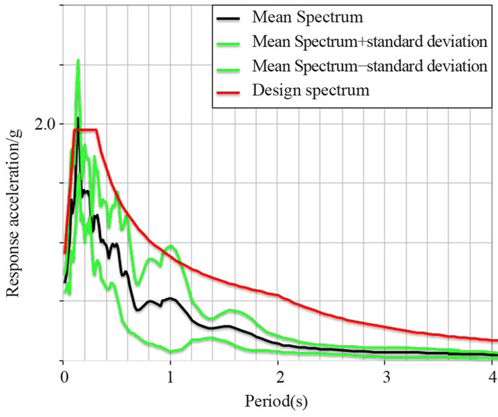
Figure 2. The elastic design spectrum (normalized by means of the gravitational acceleration g = 9.81 m/s2).
The four corner cores have a height to depth ratio of about 30 and are therefore not able to stiffen the tower even if the coupling floor beams are considered. The necessary lateral stiffness and load-bearing capacity can be achieved only if the whole building width is activated. In that case the height to depth ratio becomes about 10. An “outer tube” has to be therefore created. This has been realized by coupling the RC cores by means of X-crossed façade diagonals made of steel sections (Figure 4). On aesthetical grounds the façade diagonals were not desired at the sky foyers, so that a discontinuous bracing has to

Figure 3. Floor’s RC structure

Figure 4. Coupling façade diagonals and steel members cast within the core’s external walls.
be used. In order to avoid the transfer of the high internal forces from the coupling steel diagonals to the RC walls and back, a steel construction has been provided within the exterior walls of the cores (see the diagonal and horizontal cross-bars as well as the vertical bars depicted in Figure 4). In this way a composite stiffening system has been created, which combines the RC one made of the corner cores and the coupling floor beams with a spatial steel truss (Figure 5). To accommodate the embedded steel profiles the external walls of the cores have thicknesses varying from 1 m at the ground level and 45 cm towards the top. The corresponding internal walls are 75 and 40 cm, respectively. The coupling effect of the fa- çade bracing is outlined in Figure 6. The overturning bending moment M0 induced by the seismic action yields internal axial forces N and bending moments M within the cores. Their relative magnitudes depend on the relative stiffness of the two stiffening components, i.e. the cantilevered cores, on one side, and the spatial truss with very stiff flanges, eccentric joints and missing diagonals, on the other side. The truss response to loading is similar to that of a “Vierendeel” beam, except that the coupling between the flanges is realized by means of axial forces within the diagonals instead of bending moments within the connecting members. Due to the relatively high bending stiffness of the cores and to the flexibility of the discontinuous bracing the spatial truss takes over only some 3/4 of the seismic action during an elastic seismic response.
An additional coupling element has arisen at the top of the tower cores from the walls existing over the height of the last two minaret stories, i.e. 9 m. They are aligned with both the external and the internal walls of the cores. The internal walls have been required to fix the summit tube in the minaret cores. These coupling walls were designed as composite concrete—steel and included steel trusses too, in order to control the concrete cracking during a strong earthquake and ensure a durable ductile be-
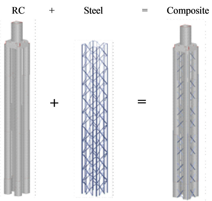
Figure 5. Lateral stiffening system.
havior. The steel trusses within the external walls are connected with those existing in the core walls (see Figure 4). The steel trusses within the internal walls transfer the internal forces to the RC walls over the height of two stories.
The enlargement of the tower foot to the foundation foot required a stiff box over the height of the basement. This has been achieved by means of a grid of RC walls (Figure 7). They were designed to safely carry the vertical and horizontal forces induced at the tower base. The basement walls depicted yellow in Figure 7 are placed beneath the core walls.
The foundation is composed of a 3 m thick foundation slab and 64 “barrettes” (short sheet pile walls). The “barrettes” have a cross-section with the thickness of 1.2 m and the length of 7.2 m at the exterior of the foundation
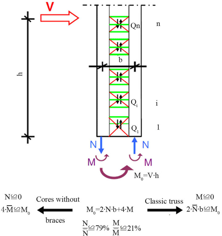
Figure 6. Global effect of the façade bracing.
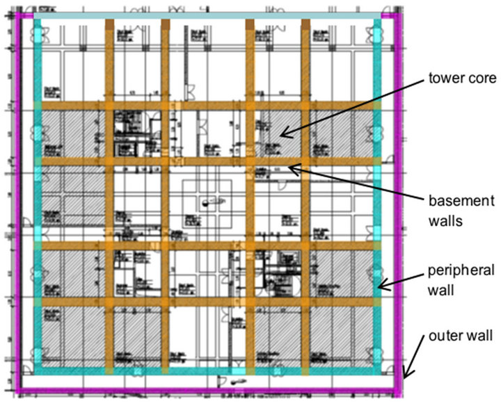
Figure 7. The RC walls within the basement (plan view).
slab and, respectively, 6 m at the interior (Figure 8). Their depth is 43 m.
4. Design Philosophy
The structural design of the minaret tower has been decisively influenced by the existing strong seismic risk and by the client requirement for a millennium lasting monument. The aseismic design of structures has been made in accordance with the performance criteria recommended by [3]. Accordingly, in order to ensure optimal energy dissipation during the design earthquake, one has to protect the “fragile” members by increasing their resistance whereas the “yielding” members have to possess a high ductility.
To ensure a best possible combination of load-bearing capacity and ductility the main structural elements, i.e. the cores, their façade bracing, the basement walls, the foundation slab and the “barrettes”, have been designed according to the following categories:
- Highly dissipative members (HDM), i.e. structural elements which will be the first to yield and hence have to possess a high ductility. They will dissipate the most part of the energy induced by a strong earthquake and will also act as “fuses” within the structure by topping the magnitude of the internal forces induced.
- Less dissipative members (LDM), i.e. structural elements which will suffer small, respectively moderate plastic deformation during the design earthquake.
- Elastic members (EM), i.e. structural elements which should remain elastic during the design earthquake. The load bearing capacity of these members should be so scaled, that the higher the risk of a fragile collapse the higher the existing resistance.
The necessary scaling of the members resistances is achieved by applying the method of “design capacity”. When two structural members are connected, the less ductile one should have a higher load-bearing capacity as the other.
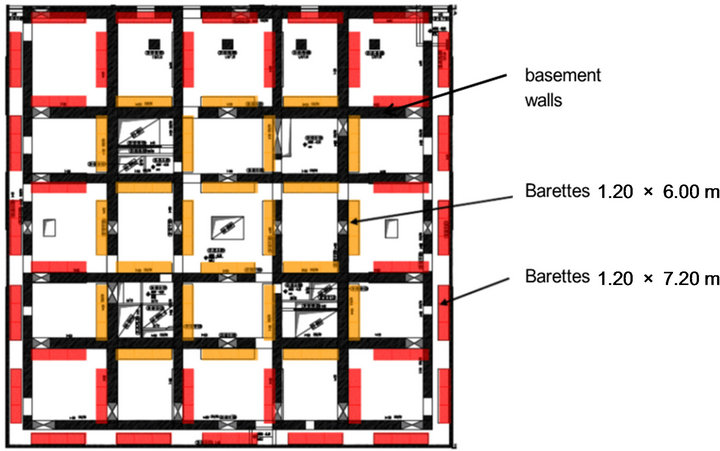
Figure 8. Foundation system (plan view).
This design concept is outlined by the seismic structural response depicted in Figure 9. The magnitude of the internal forces induced by the design earthquake within the structure is dependent on the forces at which the highly ductile members start to yield. Each point on the curve corresponds to a member yielding. The lower the internal force at the first yielding is and the more HDmembers yield, the lower the total force induced by the seism. At the same time the earlier a HD-member enters his plastic range of behavior, the higher should be its ductility. The seismic performance of the structure depends crucially on the safety margin between the maximum horizontal displacement expected to be induced by the design earthquake (in Figure 9 denoted as “displacement demand”) and that which the structure is capable to undergo without attending a major disruption.
Figure 10 shows for which category the structural elements of the minaret have been designed. The chosen “fuses” for a strong earthquake are the façade bracings and the main floor coupling beams. In case of the façade bracings only the central parts of diagonals are designed to dissipate energy through plastic deformation. They are made of steel grade S235 which is very ductile and has less strength than the grade S355 used for the other steel profiles. In order to top the induced forces it has been required that the yield strength of S235 must not exceed 245 MPa. The dissipative parts of the façade bracing are bolted with the rest, so that they can be easily replaced after a very strong earthquake, if necessary.
5. Analysis
To achieve and check out the aseismic design concept according to Figures 9 and 10 several analytical approaches have been used: modal analysis, push-over analysis and design capacity method. Seismic actions parallel to both the façades and to the floor diagonals have been considered.
The building weight has been either increased by 10% [3] or decreased by 20% [4] depending on which case
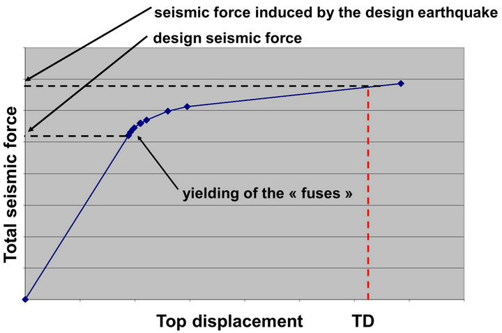
Figure 9. Relationship between the base seismic force and the top displacement (TD = displacement demand).

Figure 10. Classification of the structure members according to their designed seismic behavior.
was non-beneficial.
5.1. Modal Analysis
An elastic 3D-model of the entire structure from the foundation slab up to the very top of the building has been used. It has been assumed that the model is built-in at the base. Additional to each seismic action a simultaneous 30%—component in the perpendicular direction has also been considered [3].
The modal analyses have been used 1) to check out the compliance with the limit imposed by [3] for the elastic relative story displacement (1% of the story height), and 2) to proportion all structural members which could undergo plastic deformation during the design earthquake. To account for the plastic seismic response of the structure the design elastic seismic forces have been reduced with a “behavior” factor q equal to 3.6. The proportioning refers primarily to 1) the steel sections of the dissipative parts of the facade bracings, and 2) the longitudinal reinforcement of both ends of the coupling floor beams as well as of the cross-sections at the core bottoms.
5.2. Push-Over Analysis
The non-linear 3-D model used within the push-over analyses assumes that the tower is built-in at the ground level and made only of bars. The model has considered the geometrical effect of the box-type cores. The vertical distribution of the seismic loads has been assumed to be either rectangular or triangular [3].
The plastic behavior of the bars is modeled by means of bilinear relationships force—plastic deformation as depicted in Figure 11.
The bilinear relationships bending moments—end rotations for the RC bars (i.e. the floor coupling beams and the bottom of cores) were deducted by means of the constitutive relationships of concrete and reinforcement recommended in [5] with the mean values of both strengths and strains recommended within the Annex A. Both the confining effect of the transverse reinforcement and the influence of the axial forces have been taken into consideration. The reinforcement bars in the potential yielding zones have been designed with steel grade S500C in order to ensure the necessary ductility [5].
The bilinear relationships axial force—axial displacement for the steel bars of the façade bracing correspond to the values given in Table 1. Special requirements were imposed on the production of S235 to make sure that the actual yield stress complies with the assumed value. The façade bracings are designed with welded sturdy H-profiles. Their slenderness is less than 25 and the cross-sections correspond to class 1 according to [6].
On this account both tensile and compressive diagonals have been considered active. However, to account for the second order effects the assumed axial forces and ultimate deformations of compressive diagonals where reduced to 80% and, respectively, 75 % of the corresponding values of tensile diagonals.
For the calculation of the ultimate axial deformations of the façade bracings only the “dissipative” parts of the diagonals which are designed with S235 steel grade have been considered (see detail in Figure 10). Their length is 4000 mm at the 1st bracing and 3400 mm above.
The results of the push-over analyses are depicted in Figure 12.
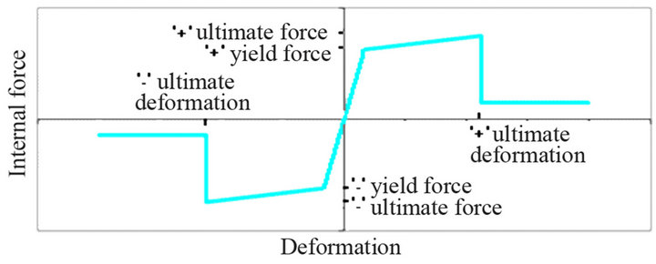
Figure 11. Bilinear force—deformation relationship used within the push-over analyses
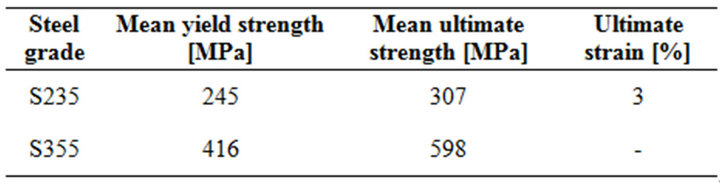
Table 1. Values used to define the constitutive relationship of steel plates with thickness up to 40 mm.
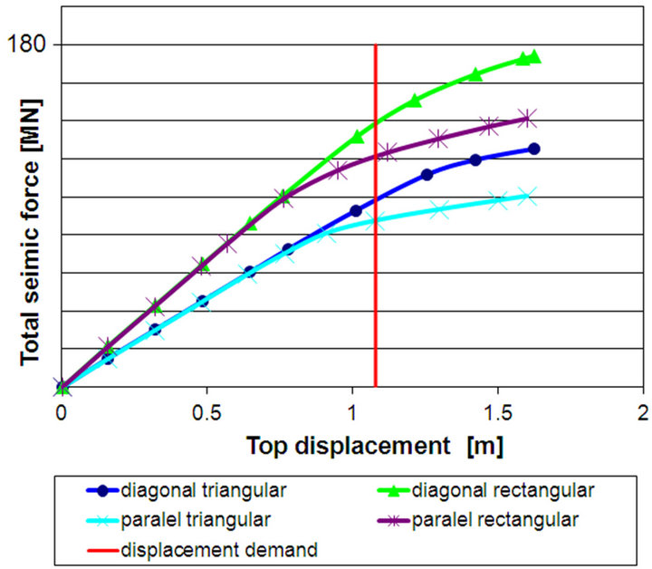
Figure 12. Capacity curves resulted from push-over analyses carried out for different directions of the seismic action and for different distributions of the seismic loads.
The red line corresponds to the displacement demand in Figure 9 and according to [3] is called “target displacement” (TD). TD has been evaluated according to the Annex B to [3] for the design spectrum from Figure 2 and resulted equal to 1.44 × 75 cm = 1.08 m, where 75 cm is the maximum displacement of the nonlinear equivalent system with a single degree-of-freedom (approximately the same for both seismic directions) and 1.44 is a factor accounting for the effect of multiple degreesof-freedom. The push-over analyses have been carried out up to a displacement 1.5 times higher than TD.
Figure 12 shows that the structure is expected to respond to the design earthquake without any significant damage and that the maximum base shear forces induced by the seism will range between 100 MN and 170 MN, depending on the direction of the seismic action and on the seismic load distribution over the building height. As expected the constant distribution yields higher seismic loads.
For comparison the corresponding values according to the modal analyses are 64 MN for the base shear force, practically independent of the earthquake direction, and 48 cm and 34 cm for the elastic top displacement when the seismic action is parallel to the façade and, respectively, to the floor diagonal.
A rough idea on the influence of the plastic behavior on the seismic response can be obtained by comparing the results of the two analyses. The ratio between the maximum seismic responses according to the push-over analysis and according to the modal analysis varies between 1.5 and 2.2 in terms of both forces and displacements. These values give a hint of the magnitude of the actual behavior factor q.
The push-over analyses yield some important detailed information on the plastic seismic response of the HDand LD-members from Figure 10, which are crucial for the energy dissipation. They are to be discussed hereafter only for the triangular vertical distribution of the seismic loads as this case is more plausible for the minaret. As expected for a mast-like tower with braced corner cores, the magnitudes of the plastic deformations of the facade bracings and of the coupling floor beams become larger when the seismic action is parallel to the façade, whereas the core dimensioning is associated with the seismic action along the floor diagonal.
The behavior of the façade bracings is depicted in Figure 13, which shows all 11 façade bracings over the minaret height as well as the steel profiles within the walls coupling the cores at their top. The given steps of the top displacement correspond to the last 5 cross— marks on the blue line in Figure 12. The points depicted “pink” denote the situations when the yielding is initialized; the points depicted “blue” the situations when the plastic deformations are smaller than 50% of the ultimate limit. As expected the compressive diagonals yield first and more than the tensile ones. At TD the largest plastic deformation occurs in the 4th bracing and reaches some 6% of the ultimate deformation. At 1.5 times TD the largest plastic deformations occur in the 6th bracing from bottom and amount to some 30% of the ultimate value in the compressive diagonal and, respectively, 20% in the tensile one. The 1st bracing and the steel bracing within the coupling walls at the top of the cores remain elastic even at 1.5 times TD.
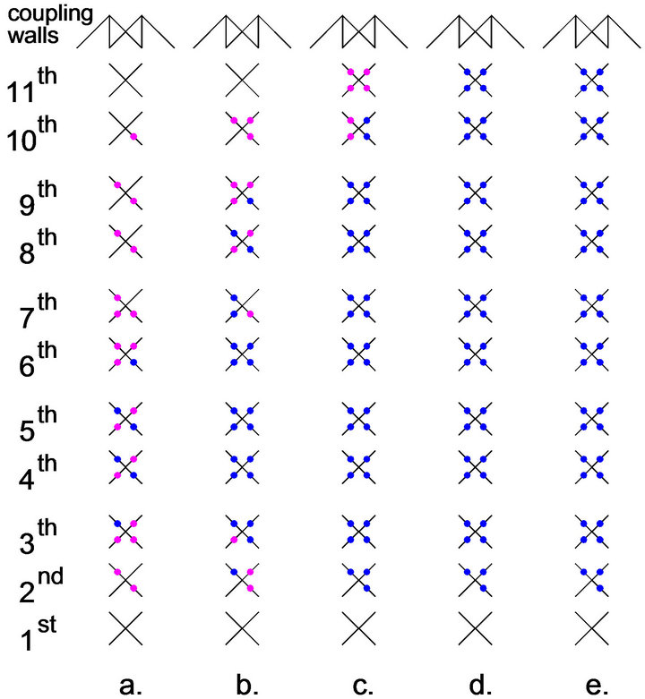
Figure 13. The degree of yielding of the façade bracings resulted from the push-over analysis carried out for the seismic action parallel to the façade with a triangular vertical distribution of the seismic loads. The situations depicted correspond to top displacements which are 85% (a), 100% (b), 120% (c), 140% (d) and, respectively, 150% of the TDvalue.
Concerning the plastic behavior of the coupling floor beams the results of the push-over analyses indicate that:
• At TD all beams of the floors situated between the 1st and the 9th bracing in Figure 13 yield, whereas the maximum plastic hinge rotation at the upper side amounts to 22% of the ultimate value and that at the lower side to 3% of its ultimate value.
• At 1.5 times TD the beam yielding extends to all floors up to the coupling walls at the top of the cores. The maximum plastic deformations occur within the floors between the tops of 3rd and the 8th bracings in Figure 13 and amount to 43% (at upper side) and 12% (at the lower side) of their respective ultimate values.
Concerning the plastic behavior of the cores at minaret base the push-over analysis yields the following results
• At TD no plastic deformation has occurred.
• The first plastic hinge occurs within the tensile core when the top displacement amounts to a value 1.4 times higher as TD.
• At 1.5 times TD the maximum plastic rotation at the bottom of the tensile core amounts to 1% of its ultimate value while all other cores behave still elastically.
6. Structural Members
The main structural members of the minaret are either RC elements (basement walls, all floor elements and the summit tube) or steel elements (façade bracings, substructure of the summit envelope) or composite elements (the cores and the coupling walls at the core tops). Some fundamental details concerning the proportioning of the bracings, of the cores and of the coupling floor beams will be presented hereafter.
When using the Euro Codes the proportioning of the structural elements must fulfill the requirement
 (1)
(1)
Ed denotes the design internal forces and Rd the corresponding resistances. For the aseismic design the Rd values are determined by means of the material design strengths, which result from dividing the characteristic strengths by the factors γc = 1.2 for concrete and γs = 1 for steel.
In the case of a HD-member the Ed value results on the basis of the modal analysis. After their proportioning and detailing the actual resistance Reff of the element can be calculated by using all existing cross-section components and more realistic material strengths as the design values, e.g. the mean values.
In the case of LDor E-members the Ed value results on the basis of push-over analyses by considering a top displacement equal to TD or more. The higher the top displacement considered, the safer is the proportioning of these elements.
In the special case of possible fragile collapses (e.g. bolted connections of steel members or shear resistance of RC elements required to behave ductile) the Ed values results by means of the “capacity design” method.
6.1. Steel Bracing
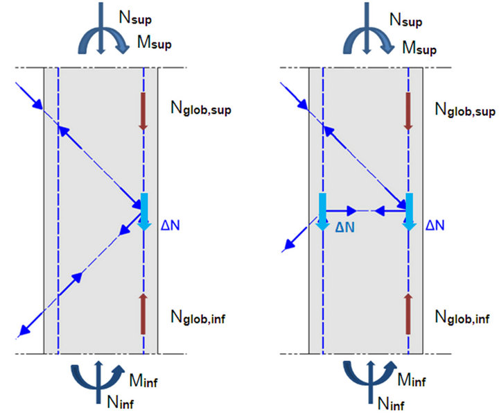
To the steel bracing belong not only the facade diagonals but also the steel profiles embedded within the core external walls (see Figure 4). The axial forces in the façade diagonals are given by their real resistance Reff. On the basis of these forces the associated axial forces within the other steel bracing members can be determined by simply using equilibrium conditions. For the vertical steel members situated in the three external corners of the cores these axial forces represent only a local modification ΔN of the global axial forces Nglob resulting from the seismic response of the structure (Figure 14). Indeed the vertical steel members reinforce the core cross section and the Nglob forces are associated with the sectional forces N and M in Figure 6. Due to the stud connectors the local modifications ΔN are transferred to the other components of the core wall, i.e. to concrete and longitudinal reinforcement bars, so that the effect of ΔN disappears at a certain distance beneath the corresponding node and is already included within the global force Nglob. It has been assumed by the proportioning of the strut connectors on the vertical steel profiles that the transfer of the ΔN takes place over a length of a story height. When the vertical steel member is elastically stressed, ΔN is transferred both above and beneath the corresponding truss node. When the vertical steel member
 (a) (b)
Figure 14. Superposition of local and global axial forces of the vertical steel members embedded in the core external walls: (a) over the height of a sky foyer, and (b) over the height of a story without façade diagonals.
yields, ΔN is transferred only above the corresponding truss node, i.e. there where an unloading takes place.
Typical details of the steel bracing in elevation and in plan are depicted in Figures 15 and 16, respectively. The exterior vertical member is embedded at the junction of both external core walls. Its cross-section is made of two identical parts placed within each of the two external walls. The two parts are welded together at every node of the spatial truss (Figure 17). The interior vertical member is embedded in the external core wall at its junction with the internal core wall. To reduce the slenderness of the façade diagonals the central node of the X-cross joint is hold horizontally in the plane of the corresponding RC floor.
All connections to be executed on the construction site are bolted. The positions of all these connections were dictated by geometrical, transportation and erection criteria.

Figure 15. Typical elevation of the steel bracing.
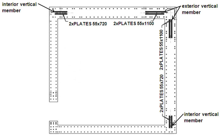
Figure 16. Core’s composite cross section. The section depicted here corresponds to the middle part of the core height.
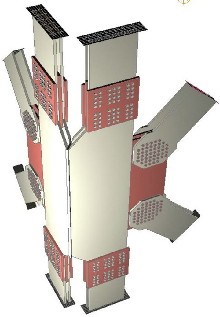
Figure 17. Detail of the corner joint of the spatial steel truss.
Basically the design of the cross section areas and of the connections in Figure 15 follows the concept already described in conjunction with Figure 10.
• The parts of the façade diagonals with the cross section area As,2 made of highly ductile steel grade S235 act as “fuses” for the entire steel bracing.
• The other parts of the facade diagonals and the embedded diagonals have the same cross-section areas but are made of steel grade S355. The ratio between the yield strengths of the two steel grades is equal to 355/235 ≈ 1.5, i.e. large enough to ensure that the S355 parts remain elastic.
• The bolted and fillet weld non dissipative connections are also designed with a sufficiently safe overstrength relative to the steel profiles. The resistance Rbd of the bolted shear connections fulfills the relation [3]
 (2)
(2)
Rsd denotes the resistance of the connected dissipative part and is calculated with the cross section area As,2 and with the design yield stress fsy,d of S235. The factor 1.1 accounts for the possibility that the real value of fsy,d may be larger than considered, the factor 1.25 accounts for the necessary overstrength of a non dissipative connection and the factor 1.2 accounts for the necessary overstrength of shear resistance relative to the design bearing resistance. The resistance Rwd of fillet weld connections fulfills the relation [3]
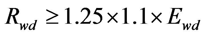 (3)
(3)
The acting force Ewd is associated to Rsd and equal to the local force ΔN in Figure 14.
• The non dissipative connections made by means of full penetration butt welds are deemed to satisfy the overstrength criterion [3].
The two parts of the exterior vertical member in Figure 17 can receive different local forces ΔN depending on the earthquake direction (Figures 18 and 19). In the
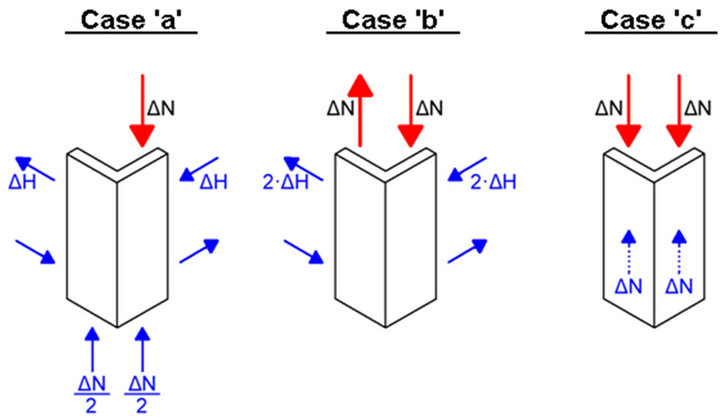
Figure 18. Possible local loading of the exterior vertical member dependent on the earthquake direction.
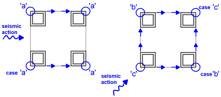
case “c” the two parts are similarly loaded, so that their connection is not stressed. On the contrary in the case “b” the connection is mostly stressed. The existing eccentricity between the forces ΔN yields a local rotational moment within the core external wall, which additionally stresses the strut connectors and which has to be considered by the proportioning of the horizontal reinforcement of the core external walls.
6.2. Coupling Floor RC Beams
During the design earthquake plastic hinges occur in both directions at both ends of the main beams of the RC floors (Figure 3). Additionally to the flexure produced by seismic action and gravity loads the outer main beams are also subjected to permanent tensile forces. Indeed the steel diagonals are compressed by the structure weight, push the adjacent cores apart of each other and therefore tension the floor beams (Figure 20(a)). The imposed compressive force D and subsequently the imposed tensile force NB increase with the relative vertical shortening Δv of the cores and decrease with the elongation u of the RC beams. The creep of concrete core acts negatively while the cracking of the floor beams is beneficial. The final NB corresponds to (3) in Figure 20(b), where εv = Δv/H denotes the vertical strain associated with the relative vertical shortening Δv and the factor A is equal with 2/3∙Es∙AsD∙sin2α∙cosα. Following notations are used: Es = steel modulus of elasticity, As = total sectional area of the beam’s longitudinal reinforcement, AsD = the sectional
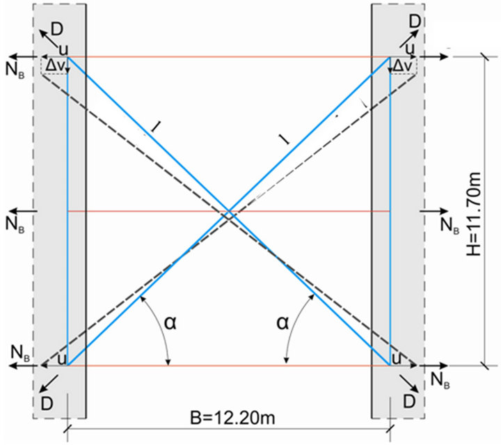 (a)
(a)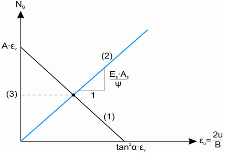 (b)
(b)
Figure 20. Effect of the core vertical shortening on the cracking of outer floor beam.
area of the steel diagonal, ψ = parameter accounting for the beneficial effect of the tensile concrete on the actual beam elongation.
The straight line (1) in Figure 20(b) describes the effect of Δv on NB and the straight line (2) corresponds to the beam elongation.
There is a correspondence between the final NB value and the calculated crack opening. It has been attested that the crack openings comply with the limit of 0.3 mm imposed by [5] for indoor RC elements.
6.3. Composite Cores
The cores have a composite cross-section (Figure 16). The concrete has the class C50/60, the steel used for the reinforcement bars has the grade S500 and the embedded steel members are made of steel grade S355.
The necessary vertical reinforcement arose from the bending of the tower in a diagonal direction, whereas the necessary horizontal reinforcement arose from the bending of the tower in a direction parallel to façade. The results of the push-over analyses for the top displacement equal to the TD—value have been used. However the proportioning has been performed by means of bending moment envelopes of the results of both modal and pushover analyses, as the push-over analysis did not capture the influence of higher vibration modes. A typical example is given in Figure 21.
The vertical reinforcement at the bottom of the minaret has been finally decided by the internal forces of the tensile core. The safety margins of the both most stressed core cross-sections are outlined in Figure 22 by means of the difference between the acting bending moments MEd and the resistant moments MRd. The corresponding axial forces N are 265 MN (tension) and, respectively, 609 MN (compression).
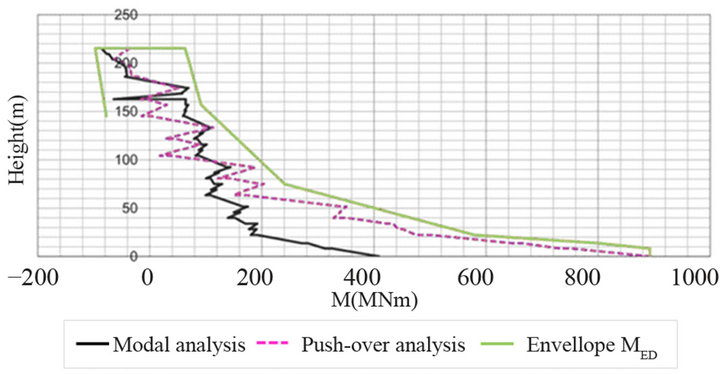
Figure 21. Bending moments of the compressive core by an earthquake along the floor diagonal.
 (a)
(a)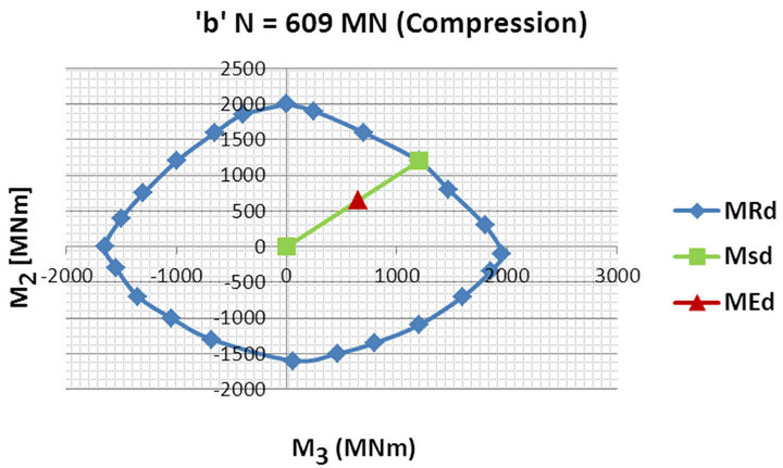 (b)
(b)
Figure 22. Relationship between the acting design bending moments MEd (red point) and the resistant moments MRd (blue interaction diagram) for the tensile (a) and the compressive (b) cores at the minaret base when the design earthquake acts along the floor diagonal.
The proportioning of the horizontal reinforcement is based on the envelope of the tower shear forces depicted in Figure 23. It has the form prescribed by [3]. The assumed value VEd,base corresponds to the rectangular distribution of the seismic forces over the tower height and to a top displacement 1.5 times higher than TD (Figure 12). This aimed at ensuring a higher resistance to shear than to bending. The ratio between the total seismic forces considered for the two situations is 140 MN/100 MN = 1.4.
The required horizontal reinforcement of the core walls arises from the design shear forces of the walls. To obtain these, the floor shear force from Figure 23 had to be distributed first to the cores and afterwards to the core walls resisting shear. The distribution factors were chosen by means of the elastic model used for the modal analyses. Both the earthquake direction parallel to façade as well the direction along the floor diagonal were analyzed.
Concerning the distribution of VEd between the four cores it has been found that 1) it is practically equal, i.e. VEd,core ≈ 0.25 × VEd, when “parallel” earthquake and that (ii) each of the two cores situated on the diagonal along which the “diagonal” earthquake acts overtakes only some 20% of the floor shear force, so that the relevant design value became VEd,core ≈ 0.3 × VEd.
Concerning the distribution of VEd,core between the resisting walls it has been found that it can be considered proportional to the wall thickness if a corrective factor is used for the external wall. The value of 1.15 has been found conservative in the case of the “parallel” earthquake, which has proved to be decisive for the required horizontal reinforcement. The required horizontal reinforcement Asw/s (cm2/m) has been determined by means of Equation (1) with Ed taken equal to the value of VEd,wall as yielded by the described distribution of VEd and Rd taken equal to the value
 (4)
(4)
hw denotes the length of the wall cross section.
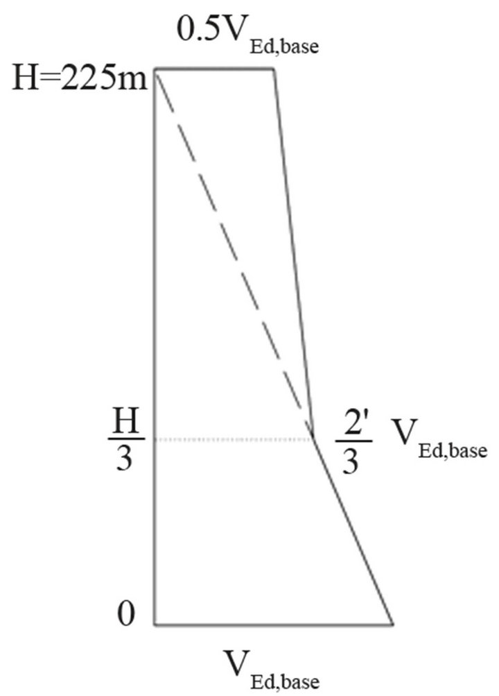
Figure 23. Design shear forces VEd.
The required horizontal reinforcement has been provided over the entire story height neglecting therefore the major beneficial contribution of the steel bracing. Indeed over the height of the stories with braced façade the steel diagonals overtake the most part of VEd whereas over the height of the other stories the steel diagonals embedded in the external walls have an important contribution to Rwd,wall. The additionally provided shear resistance accounts for the negative effects of local horizontal tensile stresses (e.g. see the discussion made in conjunction with the case “b” in Figure 18) and prevents the cracking caused by the composite action.
7. Foundation System
To this system belongs the rigid box-type enlargement of the minaret foot over the height of the two underground levels, the foundation slab and the “barrettes”. All structural members are of cast-in RC with concrete C50/60 (the basement walls) and C30/37 (floors, the foundation slab and the “barrettes”) and with reinforcement bars of steel grade S500. In accordance with the general design philosophy of the minaret, the foundation system has a higher seismic resistance as the tower itself. Moreover the resistance is increased gradually from the tower base to the foundation soil.
The design of the underground levels and of the foundation slab has been performed by means of a 3D-elastic model loaded with forces at the core bottoms and supported by elastic springs at the centers of “barrettes” and concomitantly by the subgrade soil.
The walls were modeled with membrane finite elements and the slabs (floors and foundation) with slab— membrane elements.
The forces at the core bottoms correspond to the results of the push-over analyses for a top displacement equal to 1.5 times TD. The axial forces and the biaxial bending moments at the base of each core have been considered by means of equivalent vertical forces applied at the corners of each core. The base shear forces have been given at the geometric center of each core. Different directions of the seismic action have been considered.
Each supporting point resists 3D displacements, i.e. two horizontal and one vertical. The corresponding spring stiffness values have resulted from the analyses of the soil-structure interaction reported below. The RC walls have to resist huge in-plane forces caused both by the cantilever action associated with the enlargement of the tower foot over the basement height and by the large seismic forces. These forces have required wall thicknesses up to 1.5 m and up to 8 layers of reinforcement grids.
A special attention has to be paid to two “hanging” effects. The first corresponds to the anchorage of the tensile forces within the steel members at tower foot and the second to the anchorage of the tensile “barrettes”, i.e. of those withstanding the foundation uplifting.
The first effect can occur either at the junction of the tensile façade diagonal with the interior vertical steel member or at the minaret corner when the vertical steel member is subjected to tension. The corresponding anchorage has been realized by embedding steel members over the entire basement height (Figure 24) and by providing sufficient vertical and horizontal reinforcement to spread the tensile forces and lead them into the foundation slab.
The second effect occurs at the border of the foundation slab at the junction with the “barrettes” which prevent the building’s uplifting. Due to the magnitude of the “barrette” tensile forces (up to 37 MN) and to the cantilever caused by the eccentric peripheral wall (Figure 8) the foundation slab must resist very large shear forces.
To realistically capture the soil-structure interaction an elastic 3D model with volumetric finite elements has been used. It consists of a 9 m thick foundation slab, of the “barrettes” and of the foundation soil. With the chosen thickness the modeled foundation slab has the same flexural stiffness as the entire box-type basement. The soil characteristics have been chosen according to the results of in situ soil tests carried out by the National Geotechnical Laboratory at Algiers (LCTP). A vertical section through the foundation soil is given in Figure 25. The barrettes traverse a thick sand layer and penetrate into the marl layer.
The forces acting at the core bottoms have been taken larger than the ones used to design the basement and foundation slab. Thus the vertical forces at the core corners associated with the seismic action have been amplified by the factor 1.05 whereas the horizontal forces by the factor 1.15. The higher amplification of the horizontal forces should cover the possibility that the total seismic force could act lower as assumed. Eight directions of
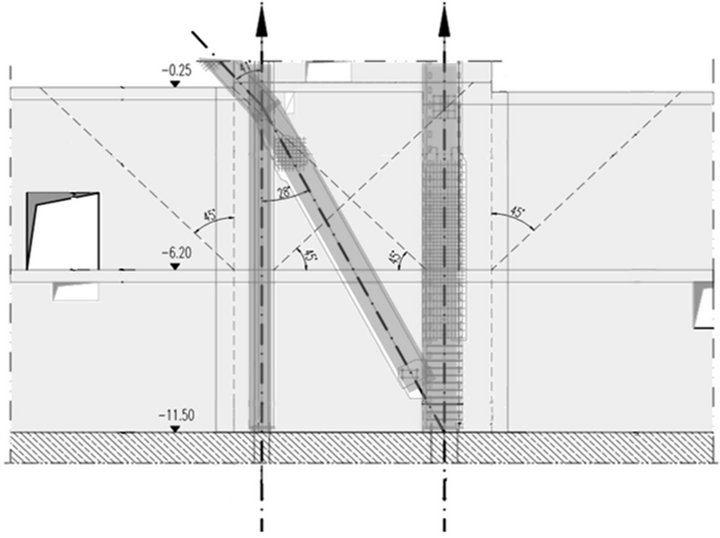
Figure 24. Anchorage of the tensile steel members at the tower bottom within the basement.

Figure 25. Geotechnical profile.
the seismic action have been considered, i.e. for both directions of each of the following seismic actions: parallel to the two adjacent façades and to the two floor diagonals. That was necessary in order to capture the influence of the different depths of the soil layers.
The modeling has shown that the soil is capable of carrying the forces induced and, as same time, has provided the internal forces and the 3D settlements at the “barrette” tops. These results have been used 1) to proportion the required barrette reinforcement, and 2) to evaluate the springs stiffness needed for the modeling of the basement and of the foundation slab.
8. Concluding Remarks
The design of the lateral stiffness and resistance of the minaret has been decisively affected by the expected seismic action. The wind action has been investigated by means of wind-tunnel tests carried out with 1/400 models. Both rigid and deformable models have been investigated. They have shown that the expected base shear force induced by the local wind conditions will reach about 25 MN, which is several times smaller than the design base shear force induced by the design earthquake. Push-over analyses indicated values of 100 MN - 140 MN for the latter forces, depending on the earthquake direction and on the distribution of the seismic forces over the tower height. According to these analyses the expected maximum displacement at the tower’s top amounts to 1.08 m and is associated with a non-linear seismic response.
The aseismic design has been performed on the basis of the performance criteria recommended by [3], which aims at ensuring optimal energy dissipation during the design earthquake and at protecting simultaneously the structural members which are to respond quasi elastically. The requirement for elastic response arises either for those structural members and connections whose collapse may be fragile or for components of the foundation system whose behavior depends on the soil response.
Consequently the member’s strength has been gradually increased from the highly ductile members over the less ductile ones up to the members which should respond elastically. The first category includes the façade steel bracing and the RC main floor beams. The second includes the bottom region of the tower cores and the coupling structural walls at the top of the cores. The latter category includes the rest of the core height and the members of the foundation system, i.e. the box-type basement, the foundation slab and the “barrettes”.
The push-over analyses confirmed the design philosophy. Plastic deformations were registered only within the zones with ductile behavior and their maximal values have had a large safety margin to the ultimate ones, even for top displacements larger than 1.5 times TD.
Due to the strong seismic conditions, to the tower slenderness and to the discontinuous façade bracing, the structural design of the minaret has faced some challenging aspects. The paper has outlined the most important of them.
9. Acknowledgements
We do thank all the colleagues who participated at the design and detailing of the minaret tower. The contributions of K. Golonka, M. Friedrich and M. Neacsu with his team deserve a special acknowledgement.
REFERENCES
- J. Engel, “Djamaâ el Djazair. The New Mosque at Algiers,” Symposium ‘25th Anniversary of Krebs & Kiefer Karlsruhe’, 2013, (unpublished).
- D. Constantinescu and J. Akkermann, “Auslegung von Bauwerken gegen Erdbeben nach Eurocode 8. Anwendung am Beispiel internationaler Projekte,” Proceedings of the Dresden Conference on Steel Constructions, Dresden, 24 March 2011, pp. 205-252.
- Eurocode 8, “Design of Structures for Earthquake Resistance, Part 1: General Rules, Seismic Actions and Rules for Buildings,” European Committee for Standardization, Brussels, 2004.
- RPA 99, “Règles Parasismiques Algériennes,” Centre National de Recherche Appliquée en Génie Parasismique, Algiers, 2003.
- Eurocode 2, “Design of Concrete Structures, Part 1-1: General Rules and Rules for Buildings,” European Committee for Standardization, Brussels, 2002.
- Eurocode 3, “Design of Steel Structures, Part 1-1: General Rules and Rules for Buildings,” European Committee for Standardization, Brussels, 2002.