Modern Mechanical Engineering
Vol.2 No.4(2012), Article ID:25133,6 pages DOI:10.4236/mme.2012.24018
Structure Parameters Optimization Analysis of Hydraulic Hammer System*
College of Automotive Engineering, Shanghai University of Engineering and Science, Shanghai, China
Email: ygpljyl@163.com
Received July 3, 2012; revised August 6, 2012; accepted August 21, 2012
Keywords: Hydraulic Hammer; Structure Parameters; Optimization Analysis; Impact Performance; ADAMS
ABSTRACT
In order to improve the impact performance, the structure of hydraulic hammer should be optimized. In this paper, the ranges of eight vital structure parameters of piston and reversing valve system of hydraulic hammer were selected firstly; and then found the best value of different parameters under experiments with the method of computer optimization and the parametric analysis method provided by ADAMS software. These methods worked and the best design values of parameters of hydraulic hammer were obtained. At last, the optimal impact energy of virtual prototype of hydraulic breaking hammer was calculated and compared with the original impact performance. The results reveal that impact performance of hydraulic hammer has been improved significantly.
1. Introduction
Hydraulic breaker, mainly consisting of three essential parts—piston, distribution valves and accumulator, is a breaking tool that converts hydraulic energy to mechanical impact energy and outputs impact energy via hydraulic pressure driving the piston to do reciprocating motion [1]. Owing to its remarkable features, such as high impact energy and productivity, superb use security, favorable working adaptability and reliability, it is widely applied in breaking mine rocks and engineering construction such as demolition of the concrete components and reconstruction of the old city [2,3]. Despite its significant function, many problems are still existed in hydraulic hammer industry, such as the theoretical analysis; processing technology research and the test method. And the most important issue is how to improve the impact performance of hydraulic hammer [3]. In order to improve the impact performance, the structure of hydraulic hammer should be optimized. In this paper, some vital structure parameters were chosen and optimized. After optimization, the results reveal that impact performance of hydraulic hammer has been improved significantly.
2. Selection of Hydraulic Hammer Optimization Goal and Design Variable
As far as the current level of control theory development, the problem that how to match subsystem for nonlinear systems in order to achieve an optimal system was not be well resolved in theory. In the system of hydraulic breaking hammer, the relationship between valve and piston is close and interdependent, so it’s hard to find a separate valve for optimal performance or a separate piston for optimal performance to compose an optimal performance broken hammer system. Hence, the ultimate goal of optimization design of hydraulic hammer is to obtain a set of optimal structure parameters of the whole hydraulic breaking system, but not necessarily to meet the need of optimal performance of each subsystem [4].
2.1. Selection of Optimization Target
This paper selected the impact energy of hydraulic breaking hammer as the optimization goal, which has close relationship with the impact performance [5]. Impact energy of hydraulic breaking hammer is defined as, under the stipulated conditions, the energy produced during the single impact of piston of hydraulic hammer.
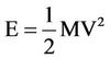 (1)
(1)
where, E is the impact energy of hydraulic hammer, M is the piston quality of hydraulic hammer, and V is the final impact velocity of hydraulic hammer piston.
2.2. Selection of Design Variables
According to the final impact velocity of piston, the impact energy of the piston can be calculated. Theoretical analysis and experimental results show that the piston velocity has relation with system parameters, such as input quantity of system and initial inflation pressure of nitrogen room [6,7]. What’s more, it has relation with structural parameters of system, such as effective work area of former and rear cavity of piston and the location of feedback hole of return and impact stroke and so on.
Energy consumption of reversing valve core consists of three main areas: the first one is the hydraulic energy losses, the second is the valve port throttling losses, and the third is leaking loss. They have direct relationship with effective work area of former and rear cavity of reversing valve core, and the location of reversing signal port of valve core [8]. When these parameters were changed, reversing velocity of valve core and the quantity of hydraulic oil will be changed correspondingly [9].
Through the analysis above, structural parameters of hydraulic hammer system that need to be optimized are listed in the Table 1 in detail.
In order to enable optimum results more reliable, the actual working condition was referenced in experiment. Measured values of working parameters were imported into ADAMS [10], i.e. working pressure is 10 Mpa, initial inflation pressure of nitrogen room is 0.8 Mpa, oil return back-pressure is 2.3 Mpa and travel of piston is limited in 90 mm.
3. Design and Study of Structural Parameters
In order to observe the effects of structural parameters on impact performance of hydraulic hammer system, the following design and study of these parameters is to find
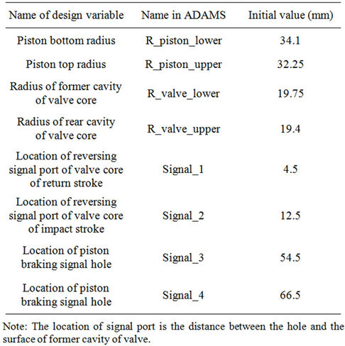
Table 1. Design variables need to be optimized.
which parameters have the maximum influence on the impact performance within the scope of the design respectively.
3.1. Design and Study of Piston Parameters
Impact energy is associated with the final impact velocity, which is related to stroke time and acceleration, while the stroke time is directly related to the travel of the piston. Besides, stroke time and acceleration are interconnected.
As can be seen in Figure 1, when the piston bottom radius is changed from 33.6 mm to 34.6 mm, the impact energy of hydraulic hammer remains unchanged, and then goes down. As the piston bottom radius increased to 34.35 mm, the piston impact energy and travel are sharply reduced. When the area of former cavity further reduced, as shown in the Trail5 of Figure 2, the piston is not work normally. So the piston bottom radius can not be too large, which should be contained within 34.35 mm. Although when the area of former cavity of piston increases, the system can achieve high impact energy, we cannot blindly increase the operation area. Because from Trail1 of Figure 2, we can see that when the bottom radius is 33.6 mm, whose travel is close to 90 mm, approaching the alert value of piston stroke travel, and impact energy is not rising than that bottom radius is 33.85 mm.
Through design and research comprehensively, piston bottom radius should be controlled from 33.85 mm to 34.35 mm.
In the same way, the piston top radius should be controlled from 31.125 mm to 33.25 mm, the location of braking signal port of valve core of return stroke should be controlled from 63.25 mm to 69.75 mm, and the location of braking signal port of valve core of impact stroke should be controlled from 54 mm to 60 mm.
Through the design and study of structural parameters of piston, the scope of each design variable was determined. Then, the sensitivity of these design variables within the scope was calculated and analyzed. The results were shown in the Figures 3 and 4.
Judging from the analysis results, the top and bottom radius of piston have higher sensitivity, and the location of braking signal port of valve core of impact stroke and return stroke have a much lower sensitivity, but their mutual impact on the impact energy can not be overlooked. So, the relation of the location of braking signal port of valve core of impact stroke and return stroke, and the relationship between the top and bottom radius of piston will be analyzed in experimental study of structural parameters.
3.2. Design and Study of Structural Parameters of Reversing Valve Core
The ranges of valve core structure parameters can also be
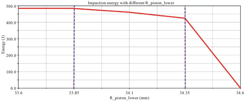
Figure 1. Impact energy curve.
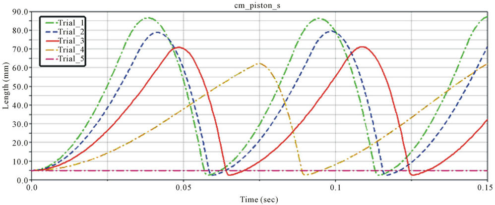
Figure 2. Piston displacement curves.
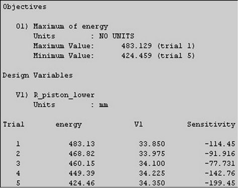
Figure 3. Sensitivty of bottom radius of piston.
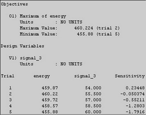
Figure 4. Sensitivty of location of piston stroke signal port.
determined through experiment initially. The working area of former cavity of reversing valve should be controlled from 19.55 mm to 19.75 mm. And the working area of rear cavity of reversing valve should be controlled from 19.05 mm to 19.55 mm. When the location of signal port of valve core of return stroke moves up, both the piston travel and the impact velocity increase, but the overall change is relatively small, and the influence on the impact energy is not very significant. On the contrary, the location of signal port of valve core of impact stroke has little influence. The impact energy can vary within a very small area, and the piston motion characteristics recorded virtually have no change.
Through experimental analysis, R_valve_lower and R_valve_upper are more sensitive than signal_1 and signal_2. Considering from design variables singly, radii of former and rear cavity of valve core show much more influence on impact energy than the location of braking signal port of valve core of impact and return stroke, but the influence from the interaction of them cannot be ignored. In the follow-up study, depending on the influence of interaction of these variables, accurate range of R_valve_lower and R_valve_upper and optimal design value of signal_1 and signal_2 can be determined, which can improve the efficiency of optimization analysis.
4. Experimental Study on Structural Parameters
It is difficult to find a mutual influence on impact energy of virtual prototype of hydraulic hammer between different design parameters. In order to find the optimal combination of design parameters, which has the best effects on impact energy, experiments are designed to research on different design parameters combinations.
4.1. Experimental Study on Piston Structural Parameters
In order to obtain the impact performance of hydraulic hammer under the influence of interplay of different structural parameters of piston, two groups of experiment were carried out.
Before experiment,  , the ratio of working area of former and rear cavity of piston, was defined, through which the impact performance of hydraulic hammer under the influence of the value of R_piston_lower and R_piston_upper can be analyzed. Then determine the accurate value of signal_3 and signal_4, by analyzing the impact performance of hydraulic hammer under the influence of them.
4.1.1. Experimental Study on Top and Bottom Radii of Piston
After analysis of test data of piston structural parameters, the figure can be obtained, which shows the relation of impact energy and  in Figure 5. From this figure, the value of
  should be controlled from 0.5 to 0.6, whose impact energy is higher than 500 J. From experimental analysis, the range of
  is from 0.5 to 0.6, which provides reference for optimization analysis.
4.1.2. Experimental Study on the Location of Braking Signal Port of Piston
From the previous design study and sensitivity analysis of parameters, the ranges of the distance of the two signal ports are determined. The next step is to find the ratio of these two arguments, which can improve the impact energy of hydraulic hammer system.
From experimental research results, the maximum and minimum impact energy and corresponding value of two arguments are shown in Table 2.
The Table 2 shows that the impact energy changes in a small region when signal_3 and signal_4 are changed. Moving the location of the two signal ports down appropriately, the piston travel and impact energy can be improved to some extent. In short, the location of braking signal port of piston has little influence on impact performance. For the sake of reducing computing time for subsequent optimization, the value of signal_3 and signal_4 is determined as 57 mm and 68.75 mm respectively.
4.2. Experimental Study on Structural Parameters of Reversing Valve Core
On the same way, before experiment,  , the ratio of
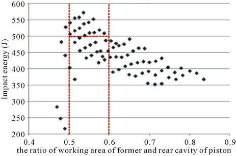
Figure 5. Impact energy distribution of different β.
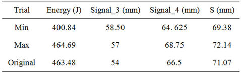
Table 2. Design of Experiments of position of brake signal.
working area of former and rear cavity of reversing valve core ,was defined, through which the impact performance of hydraulic hammer under the influence of the value of R_valve_lower and R_valve_upper can be analyzed. Then determine the accurate values of signal_1 and signal_2, by anglicizing the impact performance of hydraulic hammer under the influence of them, which were listed in Table 3. From experimental analysis, the range of  is from 1.066 to 1.2, which provides reference for optimization analysis.
From the research of experimental results, the maximum and minimum impact energy and corresponding value of two arguments are shown in Table 4.
Moving the location of the two signal holes up appropriately, the piston travel can be increased, so that the impact energy improved.
5. Optimization Design Analysis of Structural Parameters
Through the design and experiment study of structural parameters of piston and reversing valve core, final range or accurate value of each parameter was determined. In order to get maximum impact energy of hydraulic hammer and the value of the individual design variables, optimum design and analysis is needed.
After final structural parameters optimization design analysis, the parameters corresponded to optimal impact energy of hydraulic hammer was shown in table 5 and the performance comparison before and after optimization were shown in Table 6.
Through parametric analysis of design parameters, impact energy of hydraulic hammer was improved. Comparisons of impact performance before and after optimization were shown in Figure 6.
6. Conclusions
This article provides the structural parameters optimization of piston system and reversing valve core system of virtual prototype of hydraulic hammer, so that its impact energy can be improved compared with the original performance to some extent.
On the basis of the initial design parameters of original model, all of the ranges of parameters were determined by design study. Then, through the parameters sensitivity analyses, the regularity and extent of impact energy influence caused by design parameters are obtained. After parameter design research and follow-up experimental study, the efficiency of optimization analysis was greatly improved.
On the basis of four experiments on piston top and bottom radius, radius of former and rear cavity of reversing valve, location of reversing signal port of valve core and location of braking signal port of piston, two
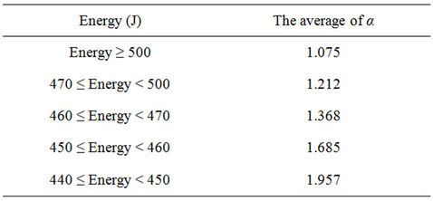
Table 3. Impact energy range with different valve area ratio.
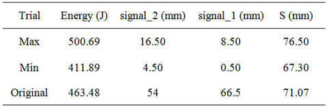
Table 4. Design of experiments of signal port location of valve.
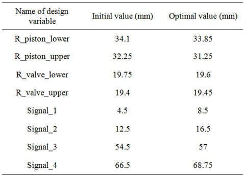
Table 5. Comparison of structural parameters before and after optimization.
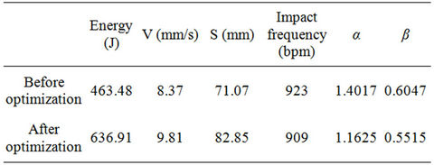
Table 6. Prototype performance comparison before and after optimization.
designed variables,  and
and , were constructed successfully. With those two variables, the locations of the four signal ports were determined, and this provides reference for optimal design.
After the optimization design analysis of structural parameters, the best design values of eight structure pa-
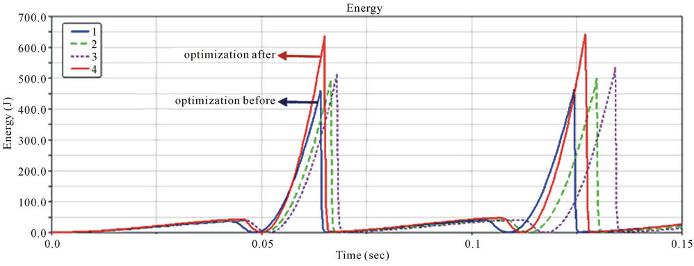
Figure 6. Impact energy cruves of the optimization process.
rameters of piston and reversing valve system were obtained, and the optimal impact energy of virtual prototype of hydraulic hammer was calculated and compared with the original impact performance. The results reveal that impact performance of hydraulic hammer has been improved significantly.
REFERENCES
- G. P. Yang, B. Chen and J. H. Gao, “Improved Design and Analysis of Hydraulic Impact Hammer Based on Virtual Prototype Technology,” Applied Mechanics and Materials, Vol. 48-49, 2011, pp. 607-610. doi:10.4028/www.scientific.net/AMM.48-49.607
- Q. Xu, Y. Y. Huang and X. Y. Tian, “Present Situation and Development Trends of Hydraulic Impactors Research,” Construction Machinery and Equipment, No. 6, 2010, pp. 47-62.
- Z. H. Zhou and F. Ma, “The Progress and Insufficiency of the Hydraulic Hammer Industry in China,” Construction Machinery and Equipment, No. 1, 2010, pp. 49-54.
- T. L. Xu, “Simulation Research on Affecting Hydraulic Hammer Working Performance,” Lubrication Engineering, No. 5, 2006, pp. 108-110.
- L. Wang, G.-P. Yang, C.-P. Liang and C.-C. Ding, “Test Method of Impact Property for Hydraulic Breaking Hammer,” Construction Machinery, No. 6, 2009, pp. 98-100.
- K. Kucuk, C. O. Aksoy, H. Basarir, T. Onargan, M. Genis and V. Ozacar, “Prediction of the Performance of Impact Hammer by Adaptive Neuro-Fuzzy Inference System Modeling,” Tunnelling and Underground Space Technology, Vol. 26, No. 1, 2011, pp. 38-45. doi:10.1016/j.tust.2010.06.011
- G. P. Yang and R. Chai, “The Key Technologies of Design and Manufacture of Hydraulic Impact Machine Piston,” Machine Tool & Hydraulics, Vol. 36, No. 6, 2008, pp. 41-43.
- T.-L. Xu, “Study of Main Technical Parameters Affecting Performance for Hydraulic Breaking Hammer,” Construction Machinery, No. 6, 2005, pp. 67-68.
- W.-C. Pei, Y.-G. Li and Y.-H. Li, “The Impact Force Models Based on the Virtual Prototype-ADAMS,” Journal of Hebei Polytechnic University (Natural Science Edition), Vol. 30, No. 4, 2008, pp. 59-63.
- L. P. Chen, Y. Q. Zhang and W. Q. Ren, “Dynamics Analysis of Mechanical Systems and Application in ADAMS,” Tsinghua University Press, Beijing, 2005.
NOTES
*This project is supported by National Natural Science Foundation of China (Grant No. 50975169).