Journal of Power and Energy Engineering
Vol.07 No.02(2019), Article ID:90698,16 pages
10.4236/jpee.2019.72004
Enhancement of Wind Energy Conversion Using Axial Flux Generator
Ibrahim Al-Bahadly, Saran Chowdary Neppalli
School of Engineering and Advanced Technology, Massey University, Palmerston North, New Zealand

Copyright © 2019 by author(s) and Scientific Research Publishing Inc.
This work is licensed under the Creative Commons Attribution International License (CC BY 4.0).
http://creativecommons.org/licenses/by/4.0/


Received: January 24, 2019; Accepted: February 22, 2019; Published: February 25, 2019
ABSTRACT
This paper investigates the application of the axial flux machine (AFM) to the wind energy conversion systems (WECS) to obtain high power and torque at reduced cost. By developing mathematical equations using the phase and active transformations, the three-phase model is transformed to two-phase equations by making both the stator and rotor as reference frames, finally converting to arbitrary reference frame, which is useful for the modelling of the axial flux machine. The torque, current, and voltage equations are expressed to improve the simulation reliability. Based on the developed equations, the mathematical model for the axial flux machine is developed using the MATLAB/Simulink. Starting with the axial flux motor model, when the load on the motor increases, how the parameters like torque, current, and speed of the motor vary are explored in this paper. Then for the axial flux generator model, when the wind speed exceeds the rated speed how the torque, line voltages, currents, power and speed of the generator behave are investigated and presented in this paper. The developed model in this paper could be extended to a twin-rotor axial flux synchronous machine, which will lead to the development of more efficient WECS.
Keywords:
Axial Flux Machine, Axial Flux Generators, Power Converter, Wind Energy

1. Introduction
Renewable Energy Resources are the future scope for the generation of the power due to the decrease in availability of the conventional energy sources and the environmental problems that are associated while the generation of power is from them. Many trends are developed in the past two decades for the generation of power using the renewable energy resources of which the Wind Energy Conversion System (WECS) plays a prominent role. WECS is the only renewable energy resource which can be placed and developed around the globe due to its main advantage of using the wind energy for the generation of power [1] which is abundant in many parts of the world. From the starting stages of WECS to the present developed technology, many types of generators are used for the power production and every generator is replaced by the other due to the disadvantages that are shown by the generators after using them for a quite long time and problems that are showcased by the generators cannot be solved and for the solution, the researchers are opting for the other model which is not having the problems that are witnessed with the older one. The present and latest generator model for the conversion process is Axial flux synchronous generator which possess more advantages and less disadvantages when compared to the other generator models that are previously used for the generation of the power from wind energy. For many years, the onshore wind farms are having more grip over the power generation from the wind energy, but these days, the offshore wind farms growth has increased rapidly due to the main advantage of having more wind speed in the middle of the water filled areas and with this more speed, the amount of power generated from the turbine is more because from the turbine and wind speed relation we know that, the mechanical power which is produced from the wind energy is directly proportional to the cube of the wind speed; when there is slight increase in wind speed it results in producing more energy from the turbine. The more the wind energy, the amount of power generated will also be more unless until there is no sudden change in the speed of the wind. In general, the wind speed will be low and doesn’t match with the synchronous speed of the generator; and to cope up with generator, the turbine is attached with gear box which is used to convert the rotational speed to the required aspect ratio. But the usage of gear box is having more disadvantages, as it increases the system cost and the mechanical losses are more, which results in the reduction of the total output power produced. The DFIG which is the present trend in the turbine’s power generation, runs with synchronous speed of about 1500 rpm which doesn’t match with the wind speed and due to this issue, the losses are more and reduce the systems reliability. To get rid of this issue, the axial flux machines are perfect solutions because the number of pole pairs can be adjusted depending on the requirement of the location wind speed and by the usage of AFM, the need for the gear box is reduced and most of the times the gear box can be eliminated and this results in high power density, better torque, low maintenance cost, less system size. The use of AFM’s is having the advantages of possessing low frictional and windage losses in the generator [2] , the output power can be doubled for the same turbine rotor diameter with the use of the twin rotor axial flux synchronous machines. If we move on to the structure of the axial flux machines, the stator is having the ring shape and the rotor is made to disc shape. The radial length from the inner radius of the stator to the outer radius is the best part to produce the torque and the axial length which is independent on the proper yoke design of the rotor and stator, which is mainly the flux-density in the stator and rotor yokes [3] . As the air gap flux direction in the axial flux machine is radial in nature, the effective number of conductors are positioned radially. When compared to the conventional radial machines, the special features of the axial flux machines of possessing greater diameter-to-length ratio and its inner diameter is having the diameter which is greater than the diameter of the shaft [4] , by which the best ventilation and the cooling techniques for the machines can be achieved and these special features makes the axial machines special and made to choose over the radial flux machines. Some of the highlighted axial flux machines, which makes them the pioneer choice for the generation of power from the wind energy are:
・ Efficient in terms of cooling is considered for the machine.
・ For the torque production large axial length is not at all required.
・ Constant tooth flux-density.
・ Rotor core is utilized efficiently.
・ The different speed operation can be achieved at a time by using the multi air-gap technology.
Different type of topologies is considered for the axial flux machines, namely, the single sided machine, double sided machine, and the motor with multi air-gaps. Various types of elements are used for the motor manufacture. The core magnets of the AFM’s are made from the Magneto dielectrics, Iron or Amorphous. Very rarely superconductors are used in the building of motor. These topologies are only made possible by varying the direction of the main air-gap flux.
Section 2 of this paper describes the components, technology and overview of the WECS. WECS’s design characteristics and the aerodynamic design followed by their power characteristics are presented. The different types of converters were used in the WECS and their control strategies are also presented in this section. Section 3 presents the necessary equations that are used to develop the axial flux machines model and the phase transformations that are made to facilitate the system modelling in MATLAB/Simulink. Section 4 presents the testing results for the developed model under different conditions. Finally, a conclusion is presented in section 5.
2. Axial Flux Machines for Wind Energy Conversion Systems
Wind Energy Conversion Systems (WECS) takes the prior position among the other renewable energy technologies and becoming popular and important day-by-day. The power production from the wind energy has become success and is showing rapid growth from last ten years when mainly compared to solar energy. The technology which is used in the early stages to produce power in wind turbines was Squirrel-cage induction generators (SCIG) and is connected directly to the grid. As the usage time of the SCIG increasing the consistent production of power is decreasing due to disadvantages it is showcasing in the wind turbine. To get more power from the wind energy, the Doubly fed induction generators (DFIG) are used as a replacement for the SCIG and the DFIG is consisting of the gear box. In the starting stages the usage of gear box has shown some advantages but as the time proceeds, the mechanical losses are increasing and make the system durability low. To get rid of all these disadvantages, after carrying many researches on the synchronous machines, the axial flux machines are chosen as the best generator for the power production in the wind turbine. The installation of the axial flux machines to wind turbines is done only when the proper care is taken for the components of the wind turbine and the technology of the power electronic components that are used.
2.1. Wind Turbine Technology
When the wind turbine conversion process is considered, the available kinetic energy from the wind is converted to the mechanical energy and this conversion process plays a prominent role in the wind energy conversion system. The captured kinetic energy is converted into electrical energy by the help of an electro mechanical subsystems, which is a generator. Finally, the electrical subsystems adapt the energy and pushes into the grid [5] . In the first stage of the conversion, the wind turbines mechanical subsystems control the yaw angle of the turbine which follows the wind direction, to make the blades face the incoming wind as much as possible. Furthermore, depending on the incoming wind speed, tip-speed ratio is needed to be regulated to maximize power co-efficient, Cp, which is the ratio of the power that is extracted by the turbine relative to the energy available in the wind. Tip-speed ratio (TSR) is the ratio of the speed of the blade, at its tip, to the speed of the wind. The second and third stages of energy conversions involve the generator, which is the axial flux synchronous generator for the transferring of the produced electricity to the grid. For the transferring of the power to the grid, the Power Electronic Converter (PEC) is used. Over the last two decades, the capacity of wind power which is installed is showing a rapid growth and increased from 6 MW to 318 MW in the recent years. On the spin axis orientation, the wind turbines are categorized into Horizontal Axis Wind Turbine (HAWT) and the Vertical Axis Wind Turbine (VAWT). In HAWT, the orientation of spin is parallel to the ground and the nacelle of the wind turbine is elevated by the tower to provide enough space for the blades of the rotor to rotate and makes the system efficient under different conditions of wind. When the VAWT is considered, the orientation of spin axis is perpendicular to the ground and the rotor of the turbine consists of vertically mounted and curved air foils and the gear box, generator and power converters are employed at the tower base.
2.2. Components of Wind Turbine
Wind turbine has several components involved in the conversion of kinetic energy available from wind to the electrical energy. The installed rotor hub on the main shaft is responsible for the conversion of kinetic energy of wind to mechanical energy with the help of mounted blades the mechanical energy is transferred to the generator through the drive chain. The drive chain consists of low speed shaft, gear box and high-speed shaft. This mechanical energy is converted to the electrical energy in the generator. If required, the power converters are used to decouple the supplied power generator from the grid. In addition to these parts, there are some other parts like mechanical brake, pitch system, wind speed sensor, wind direction sensor, yaw system, power distribution cables, tower, nacelle and foundation which are not involved directly but are important for proper, efficient and reliable operation.
2.3. Wind Turbine Aerodynamics
The aerodynamic operation of the turbine blades is explained by the Bernoulli’s principle, which states that as the speed of the moving fluid increases, the pressure within the fluid decreases. The curve shape of the blade creates the pressure difference between the air flowing above and below the blade i.e., the air flow above the blade is faster than the air flow below the blade which creates the inverse effect of the pressure [6] . This pressure difference creates the lift force on the blade. The force applied at certain distance from the pivot produces torque which creates the rotational movement of the turbine. The important factor which controls the lift force is the angle of attack “α”. Angle of attack is mainly defined as the angle between the direction of wind speed and the chord line of the wind turbine. The aerodynamic design consideration of the wind turbine has good impact on the kinetic energy which is captured from the wind. When the wind speed exist between the rated and cut in value, the blades are pitched at an optimal value so that the maximum power is captured from the wind [7] and if it is between the rated and cut outvalue, in order to limit the forces on the mechanical components and the output power within the safety margin, the pitch mechanism is activated to change “α”. For this purpose, the angle of attack can be decreased within the range of 25 to 20. If the speed of the wind is beyond the cut-out vale, the blades are completely pitched into the wind or out of wind base on the type of pitch mechanism such that no energy is captured from the wind to protect the turbine from the wind gusts. Normally there are three different aerodynamic controls in the mechanism when the pitch of the wind turbine is considered, they are passive stall control, active stall control, pitch control.
The wind power is moving at a speed of through an area A can be calculated as
(1)
where ρ is the density of air which is approximately 1.2 Kg/m3, A is the swept area in square meters, is the speed of wind in m/s.
The mechanical power Pm converted by the turbine from the captured wind power Pw can be calculates as
(2)
where Cp is the coefficient of power, which is obtained from the blade has a maximum of 0.59 theoretical value. For modern wind turbine, the Cp value is in between 0.2 to 0.5 which is function of blade number and rotational speed of the turbine. From the above equation we can observe that the mechanical power can be supervised by varying any of these three parameters: Swept are of turbine A, Wind velocity and power co-efficient. Wind velocity is uncontrollable but or better and steadier wind conditions the regions like offshores can be selected. Area swept by the wind turbine A is given by , where l is the length of the blade from pivot. With the increase in l there is a quadratic increase in the area A and thus increase the mechanical power output PM. The third possible parameter Cp is the function of TSR and angle of attack.
2.4. Maximum Power Point Tracking (MPPT) Control in Wind Turbine
In the generator control mode, the MPPT control has the vital role and is the reason where the axial flux generators have the more torque control, power density and optimum tip speed ratio. The control over MPPT can be done by three types:
MPPT with power profile of turbine: In this control the turbine power profile is given by the user. With the help of the power profile at various speeds of the wind, the reference mechanical power of the generator is generated and is compared with the measured power Pm from the generator to generate the signals that can be controlled by the power converters [8] . Thus, the mechanical power of the axial flux generator is equal to its reference value.
MPPT with optimal TSR: In this control, the MPPT operation is achieved by keeping the tip speed ratio to its optimal value . The reference generator (AFG) speed is obtained by measuring the speed of wind and setting the TSR at its optimal value. By controlling the generator speed to its reference vale using power converters [9] , the maximum power point operation is obtained.
MPPT with optimal torque control: From the relation between the speed and torque, the maximum power point is obtained by calculating the reference torque. The reference turbine speed is generated by measuring the speed of wind and by setting the optimal tip speed ratio to its optimal value. When a gear ratio is considered, neglecting the mechanical losses of the gear box, the turbine speed is converted to the generated speed . The reference torque is obtained by calculating optimum torque co-efficient and reference generator (AFG) speed. By comparing the reference torque and torque of the generator, the control signals are generated to the power converters [10] . So, that the torque of the generator is made equal to the reference torque to achieve the maximum power point operation.
2.5. Power Electronic Converters with Axial Flux Machines in Wind Turbine System
Since 1980’s the usage of the power electronics in the wind turbine systems are increased rapidly and the main operation of the power electronic device in Wind turbine system is for the soft starting of the system by using the thyristor which is by-passed and by that soft start, the direct operation of the generator to the grid made easy. From the middle of 1990’s, a diode bridge is used as a switching device for the control of rotor resistance and later it was replaced by the power converter which is connected in back-to-back mode and firstly used in DFIG’s. The better solution for the system of wind turbine when the power converters are considered is the usage of double 2-level voltage source converters with the configuration of back-to-back mode and this mode of configuration is started using the axial flux machines and is showing the better output power compared to that of the DFIG. For the alliance between the power grid and the generator (AFG) of the wind turbine, the manufacturer requirements must be satisfied by the wind power converter to both the sides. When the generator side is considered, the adjustment of the torque and rotational speed can be controlled by the stator generator when there is enough current flow in it and improves the balance of the active power when the generator is operating normally and extracting the wind turbine’s maximum power. To vary the voltage amplitude and fundamental frequency of the generator, the converter must be properly installed in the turbine. When we consider the grid side accordance with the generator link, the converter should act in accordance with the codes of the grid no matter what the speed of the wind is available to the turbine and should possess the special feature to control the capacitive and inductive power Q and the response of the active power P should be very fast. At a low level, the maintenance of the rotor currents total harmonic distortion should be done. So, the converter must be operated to meet the requirement of satisfying the grid side and generator side cost and maintenance problems and for satisfying these requirements, the converter must have high power-density, modularity and reliability. The active power storing and boosting the voltage from the side of the generator to the grid is also done by the wind power converter.
3. Modelling of Axial Flux PM Synchronous Machines
AC machines must be modelled to get the perfect output before implementing the prototype model so that what are the possible errors which may be included in the machine can be detected and can be removed by the help of the modelling. Linear transformation plays a vital role in the modelling of AC machines. All the rotating electrical machines are made equivalent to a primitive machine model in the process of obtaining the mathematical model. In primitive machine models, the magnetic field is invariant with respect to time. Many polyphase AC machines are constructed in different manner than a primitive machine. These polyphase AC machines have distinct phase windings on stator and rotor which produce the rotating magnetic field when they are excited by the polyphase supply. Hence the machine inductances change especially in non-uniform air-gap machines with respect to the rotor position which is a function of time. The Linear Transformation is the process of representing poly phase windings on stator and rotor by d, q axes coils of primitive machine. The term Linear Transformation means the transformation from old to new set of variables or vice versa governed by Linear equations. The general form of transformation is
(3)
3.1. Phase and Active Transformations
Phase transformation is also known as transformation from a, b, c to α, β, 0 transformation. Using Phase Transformation, a 3φ machine is transformed into an equivalent 2φ model with additional zero sequence system [11] .
Figure 1(a) shows a symmetrical 2 pole, 3φ winding on rotor. Each phase has N effective turns and mutually displaced by 120˚ (some turns may be distributed or short pitched). While Figure 1(b) shows balanced 2φ system with 2 orthogonal coils α and β on rotor. For convenience in transformation, the axis of phase A of 3φ system and phase α of 2φ system are taken along the same axis, when the 2φ system is excited by currents.
Fa, Fb, Fc are maximum values of mmf’s shown along their respective phase axis. These 3φ’s is excited by 3φ currents.
When the equations for the current and voltage are considered for the axial flux machines with the help of the phase transformations, they are as follows:
(4)
(5)
(6)
When the equations for the current fed by the 3-phase supply in the active transformations, they are as follows:
(7)
(8)
When the phase transformation from 3-phase to 2-phase is considered by the method of changing both the current magnitudes and the turns ratio, the necessary equations that are obtained are

Figure 1. Phase and active transformations.
After the transformation of the matrix and the simplified form of the main torque equation is given by
(9)
where the factor 3/2 is introduced to obtain power invariance between 3φ machine and d-q model and the parameters are as follows:
P = Number of poles.
= Mutual Inductance
= Rotor current at d-axis
= Stator current at q-axis
= Rotor current at q-axis
= Stator current at d-axis
3.2. Modelling Circuits of Axial Flux Machines
In this section the simulation of the axial flux machine is presented. Figure 2 shows the subsystems of the simulated Axial Flux Synchronous Motor model, and Figure 3 shows the simulated Axial Flux Synchronous Generator model.

Figure 2. Subsystems of the simulated model of Axial flux synchronous motor.

Figure 3. Simulation model of Axial flux synchronous generator.
4. Test Results
4.1. Test Results for Axial Flux Generator
・ At rated wind speed i.e., at a wind speed of 12 m/s, how the voltage, current, torques, rotor speed and output power of Axial flux generator possess the characteristics is presented here. These are shown in Figure 4.
・ At above rated wind speed i.e., at a wind speed of 20 m/s, how the voltage, current, torques, rotor speed and output power of Axial flux generator possess the characteristics is presented here. These are shown in Figure 5.
4.2. Test Results for Axial Flux Motor
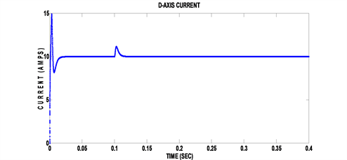
・ At no load condition, that is when there is no load applied on motor, how the currents, speed and torque possess the characteristics are presented here. These are shown in Figure 6.
・ At loaded condition, that is when there is load applied on motor, how the currents, speed and torque possess the characteristics are presented here. These are shown in Figure 7.
It can be concluded from the testing results of the simulated model for the axial flux machine that the developed model has behaved as expected under different conditions for both generation and motoring modes.
5. Conclusions
The simulation and analysis for complete axial flux synchronous machines using the mathematical modelling from the MATLAB environment were presented in this paper. Axial flux synchronous machines in WECS could avoid the use of gear box. This reduces the weight and cost of the wind turbine. Therefore, it leads to the elimination of the complicated foundation and tower design of the turbine.
 (a)
(a) (b)
(b) (c)
(c)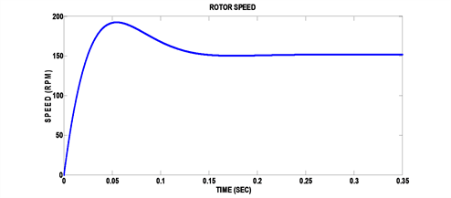 (d)
(d) (e)
(e)
Figure 4. Simulation results for Axial flux generator at rated speed. (a) Line voltage; (b) Line current; (c) Torque; (d) Rotor speed; (e) Output power.
 (a)
(a) (b)
(b) (c)
(c) (d)
(d) (e)
(e)
Figure 5. Simulation results for Axial flux generator at above rated speed. (a) Line voltage; (b) Line current; (c) Torque; (d) Rotor speed; (e) Output power.
 (a)
(a) (b)
(b) (c)
(c)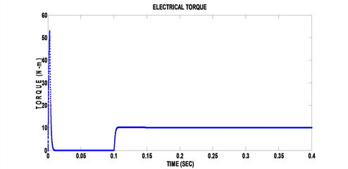 (d)
(d)
Figure 6. Simulation results of Axial flux synchronous motor at no load. (a) D-axis current; (b) Q-axis current; (c) Rotor speed; (d) Torque.
 (a)
(a) (b)
(b) (c)
(c) (d)
(d)
Figure 7. Simulation results of Axial flux synchronous motor at load. (a) D-axis current; (b) Q-axis current; (c) Rotor speed; (d) Torque.
A background research for the axial flux machines has been carried out. By exhibiting the features of having more pole pairs, the AFMs are perfectly opted for the direct-drive and low-speed applications. A single air-gap axial flux synchronous machine is modelled in MATLAB/Simulink environment and its torque, speed and respective current curves are plotted for both the generator and motor. For motor, the speed, torque, and current are presented for no load condition. Then, when the load was applied, how the speed, torque and current changes are also analysed and presented in this work. For generator, the line voltages and current, power, torque and speed are presented for the rated wind speeds. Then, how these parameters changed when the wind speed changes abruptly; the results are analysed and presented in this work.
The developed system of equations in this paper for the modelling of AFM’s model can be extended to twin-rotor axial flux synchronous machine. Where, in variable speed WECS applications, controllers and power converters can be designed for twin rotor axial flux generators to maximise output power.
Conflicts of Interest
The authors declare no conflicts of interest regarding the publication of this paper.
Cite this paper
Al-Bahadly, I. and Neppalli, S.C. (2019) Enhancement of Wind Energy Conversion Using Axial Flux Generator. Journal of Power and Energy Engineering, 7, 43-58. https://doi.org/10.4236/jpee.2019.72004
References
- 1. Carlin, P.W., Laxson, A.S. and Muljadi, E.B. (2001) The History and the State of the Art of Variable Wind Technology. National Renewable Energy Laboratory. https://www.nrel.gov/docs/fy01osti/28607.pdf
- 2. Chalmers, B.J., Wu, W. and Spooner, E. (1999) An Axial Flux Permanent Magnet Generator for Gearless Wind Energy Systems. IEEE Transactions on Energy Conversions, 14, 251-257. https://doi.org/10.1109/60.766991
- 3. Ramesh Babu, V. and Soni, M.P. (2012) A Novel Method of Using Twin-Rotor Axial Flux Induction Machine for Wind Energy Conversion and Reactive Power Compensation by TSC-TCR. International Journal of Emerging Technology and Advanced Engineering (IJETAE), 2, 399-407.
- 4. Solyali, D. and Redfern, M.A. (2009) Have Wind Turbine Stop Maturing? IEEE 44th International Universities, Power Engineering Conference (UPEC), Glasgow, 1-4 September 2009, 820-824.
- 5. Hussein, M.M., Senjyu, T., Orabi, M., Wahab, M.A.A. and Hamada, M.M. (2013) Control of Stand-Alone Variable-Speed Wind Energy Supply System. Applied Sciences, 3, 437-456. https://doi.org/10.3390/app3020437
- 6. Nikooei, V. and Bhakshali Pour, A. (2015) Static Analysis of Transit Points and Reynolds Number Influence on the Blade of a Wind Turbine as Two-Dimensional. International Journal of Innovative Research in Science, Engineering and Technology, 4, 2186-2193.
- 7. Wilson, R.E. (1980) Wind-Turbine Aerodynamics. Journal of Wind Engineering and Industrial Aerodynamics, 5, 357-372. https://doi.org/10.1016/0167-6105(80)90042-2
- 8. Allagui, M., Hasnaoui, O. and Belhadj, J. (2014) A 2 MW Direct-Drive Wind Turbine; Vector Control and Direct Torque Control Techniques Comparison. Journal of Energy in Southern Africa, 25, 117-126.
- 9. Salma, T. and Yokeeswaran, R. (2013) Pitch Control of DFIG Based Wind Energy Conversion System for Maximum Power Point Tracking. International Journal of Advanced Research in Electrical, Electronics and Instrumentation Engineering, 2, 6373-6381.
- 10. Nijiri, J.G. and Soffker, D. (2016) State-of-the-Art in Wind Turbine Control: Trends and Challenges. Renewable and Sustainable Energy Reviews, 60, 377-393. https://doi.org/10.1016/j.rser.2016.01.110
- 11. Fei, W., Luk, P.C.K. and Jinupun, K. (2008) A New Axial Flux Permanent Magnet Segmented-Armature-Torus Machine for In-Wheel Direct-Drive Applications. 2008 IEEE Power Electronics Specialists Conference, Rhodes, 15-19 June 2008, 2197-2202. https://doi.org/10.1109/PESC.2008.4592268