Journal of Power and Energy Engineering
Vol.05 No.05(2017), Article ID:76482,15 pages
10.4236/jpee.2017.55004
Reactive Power Problem and Solutions: An Overview
Ahmed A. AbdElhafez1,2, Saud H. Alruways1, Yazeed A. Alsaif1, Mutlaq F. Althobaiti1, Abdulmohsen B. AlOtaibi1, Naif A. Alotaibi1
1Electrical Engineering Department, College of Engineering, Shaqra University, Shaqra, KSA,
2Electrical Engineering Department, Faculty of Engineering, Assiut University, Assiut, Egypt

Copyright © 2017 by authors and Scientific Research Publishing Inc.
This work is licensed under the Creative Commons Attribution International License (CC BY 4.0).
http://creativecommons.org/licenses/by/4.0/


Received: April 8, 2017; Accepted: May 23, 2017; Published: May 26, 2017
ABSTRACT
This article presents a comprehensive review for the dilemma of reactive power flow, while addressing different proposed remedy strategies: conventional and most update solutions. Robust analytical expressions were utilized to exploit the functionality of the proposed solutions and to show clearly the relation between the reactive power and control variables. The article, moreover, proposes a simple, innovative and robust analysis for static performance of the STATCOM. This approach shows clearly the advantages of the STA- TCOM in regulating reactive power and maintaining load voltage level within presumable limits. The approach, furthermore, reveals explicitly via analytical expressions the impact of the STATCOM operation on different aspects of the power system under concern.
Keywords:
Compensation, TCR, TSC, STATCOM, Reactive Power

1. Introduction
Reactive power flow is a salient feature of an electrical power system. Reactive power is mandatory for the operation of different load types either static or rotating [1] [2] . For example, in rotating load as induction motor, which is the main industry motor, the reactive power is essential for producing the revolving magnetic field required for successful operation. In the transmission and distribution networks of electric power, the reactive power is required to fulfill the requirement of proper operation. The value and the direction of the reactive power in such networks vary according to load level and power factor [1] [2] [3] . These lines are essentially reactive networks of distributed parameters characterized by their series inductance and shunt capacitance [4] [5] [6] [7] .
Reactive power flow, however, has a number of undesirable consequences. It increases the drawn current for the same load level, which in turn increases the losses, maintenance and cost of the power system operation. Moreover, it reduces the power stability margin. It under heavy level of reactive power probably results in voltage instability [8] [9] [10] [11] .
Different reactive power compensating strategies are reported in the literature. These schemes vary from simple techniques such as fixed capacitor/inductor to recent approaches such as Static Synchronous Compensator (STATCOM), Static Series Synchronous Compensator (SSSC) and Unified Power flow controller (UPFC) [12] [13] [14] [15] . The recent techniques as STATCOM, SSSC and UPFC are solid-state based circuits that manipulated DC voltage and DC current to synthesize the compensated voltage/current. These schemes are revolved from traditional solid-state topologies, Static VAR Compensators (SVC), such as Thyristor Controlled Reactor (TCR), Thyristor Switched Capacitor (TSC) and Thyristor Controlled Capacitor (TCC) [11] - [18] .
The compensating techniques either conventional or recent suffer from limitations. For example, the reactive output of SVC topologies is proportional to the square of the voltage magnitude. Therefore, the SVC provided reactive power decrease rapidly as voltage decreases, which reduces its stability. STATCOM typically exhibit higher losses and may be more expensive than SVC. Moreover, STATCOM operates under balanced operating conditions; thus its performance is deteriorated under abnormal operating conditions. The UPFC, also as STA- TCOM, could not operate properly under disturbance conditions [19] - [26] .
In this article, comprehensive analysis for the phenomenon of reactive power is provided. The different indices for the reactive power are highlighted. Then, examples of reactive power compensating scheme are addressed regarding operational constraints and performance characteristics. A simple and robust analysis for the static performance of the STATCOM is advised. Simple and clear analytical expressions are advised to expose explicitly the relation between the STATCOM and different aspects of power system operation. Finally, the conclusion highlights the main points in the dilemma of reactive power.
This article has a number of objectives:
1) Providing a comprehensive highlighting for conventional and recent techniques for compensating reactive power.
2) Analyzing the static/dynamic performance of different reactive power com- pensator as a simple straightforward approach.
3) Proposing simple and innovative approach for the static performance of the STATCOM, which illustrates via analytical expression the increase in load voltage and the reduction in transmission line losses due to STATCOM operation.
2. Reactive Power and Performance Indices
As mentioned before that reactive power is elementary for some load to function; therefore the majority of loads are functioning at lag power factor which is less unity. Figure 1 shows the variation of the power factor of a load with the drawn reactive power either inductive or capacitive. The active load power is assumed 1.0 pu in generating Figure 1.
Figure 1 shows that a load power factor is heavily dependent on the drawn reactive power and vice versa. Moreover, for inadequate design the load results in flowing large reactive power and hence degrading the power factor.
Reactive power flow, as mentioned, could result in uneconomic operation of the power system, as it increases the current magnitude and hence copper and reactive losses in the transmission and distribution networks. This is shown Figure 2. The power system in Figure 2 is assumed to operate at rated voltage and 1.0 pu active power, and the line under concern has a resistance of 0.1 pu. This hypothetical value for line resistance is assumed to depict the worst design case.

Figure 1. Power factor versus reactive power.

Figure 2. Load current (star) and line losses (dotted) versus reactive power.
Figure 2 shows that current magnitude and losses increases for non-zero reactive power despite inductive or capacitive. This definitely impacts the economic operation of a power system, which eventually affects the end-line customers. To visualize the full dilemma of reactive power, Figure 3 shows the efficiency of 0.1 pu resistance power system versus the circulated reactive power. In producing Figure 3, only ohmic losses in the tranmission line are considered.
Figure 3 shows how could the flow of the reactive power impacts the efficiency. The figure shows that the efficiency is reduced under the flow of the reactive power despite its sign. This is attributed to the fact that Figure 3 is generated for uncompensated operation. The relatively low value around 90% of the efficiency at zero reactive power is due to the large value of the line resistance.
3. Reactive Power Compensation
Different techniques are emerged to remedy the problem of reactive power circulation. These approaches range from simple method to most-update approaches. Each approach enjoys merits and suffers from drawbacks. In the following, a concise highlight for these methods is addressed.
3.1. Simple Compensation Strategies
A simple compensation technique is inserting fixed capacitor/inductor [1] [2] [3] [4] . The capacitor is used for nominal/heavy load operating points to produce sufficient reactive power for boosting voltage profile at load buses. The inductor meanwhile is used for light load operating point to limit the voltage within the presumable regulation. Usually, the capacitor/inductor is inserted in the system via mechanical switch. The reactive power produced from reactive elements capacitor/inductor is obtained from the primitive equation,
 (1)
(1)

Figure 3. Efficiency versus reactive power.
where Q is either inductive or capacitive depending on X. The capacitive reactance powers produced via fixed capacitor elements are shown in Figure 4. This figure shows that pumped reactive power increases almost linearly with the capacitor value. This could be considered as a guideline for dimensioning the reactive power compensation element.
Figure 4 shows the linear dependency of the pumped reactive power from the capacitor with the capacitor value. This implies application of bulky and costly capacitor for compensating large loads. The reactive power produced from the fixed capacitor bank compensation is voltage dependent (Figure 4), as it varies with the square of the voltage at the common coupling point.
These techniques suffer from serious limitations, such as:
Fixed compensation, which limits their compensation ability;
Inability to respond for load requirements; these techniques fail to provide instantaneous response for load reactive power requirements;
Resonances, the fixed compensator capacitor/inductor values could resonate with transmission line parameters.
3.2. SVC Topologies
SVC gains more advantages than rotating reactive power compensators and fixed reactive elements, such as:
1) High efficiency;
2) Reduced volumetric dimension;
3) Relatively fast responses compared with synchronous condenser;
4) Adaptive operation, SVC could provide continuous compensation compared with fixed reactive elements. SVC could act as source/sink for the reactive power according to the control strategy;
5) Automation, as SVC are mainly solid-state devices, they could be controlled via intelligent systems as microprocessor and microcontroller.

Figure 4. Capacitive reactive power produced from via capacitor.
It is worth to mention that SVC suffers from elevated harmonic content in the output voltage and current. This would produce additional problems to the power system.
SVC for shunt operation is composed from two main topologies. These are TCR and TSC, as shown in Figures 5-7. TCR and TSC could act independently generating inductive/capacitive reactive power, or they run as one device producing variable reactive power. In SVC, the reactive passive elements are interfaced to the common coupling point via self-commutated sold-state devices. TCR consists from inductance interfaced via pair of anti-parallel thyristors. The firing angles of the thyristors are controlled in continuous manner. For TCR, there are two modes of conduction: discontinuous current and continuous current. The inductor current is continuous if the firing angle α of the thyristor is greater than π/2 and less than π. For more details, see references [22] [24] . The inductor current is given in terms of firing angle,
 (2)
(2)
The reactive power produced by TCR is given by,
 (3)
(3)
Figure 6 shows the reactive power generated from TCR at different firing angles.
Figure 6 shows that for Xpu =1.0 the produced reactive power is 4 pu. A small inductor is sufficient to produce the required reactive power. The range of the firing angles of the thyristor is limited to be 90˚ - 180˚. This is to ensure continuous inductor current conduction.

Figure 5. Thyristor based FACTS devices thyristor-controlled reactor.

Figure 6. TCR reactive power versus firing angle.
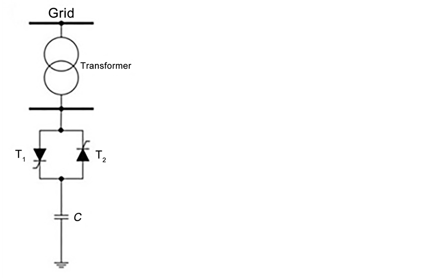
Figure 7. Thyristor based FACTS devices thyristor-switched capacitor.
TSC similarly to TCR is composed from capacitor interfaced to the common coupling point via pair of anti-parallel thyristors (Figure 7).
Here the thyristors are controlled such that current through the thyristor ITCR is function in the thyristor firing angle, α. The RMS value of the current could be obtained by,

Thus, the reactive power could be calculated by,

For more details, see references [22] [24] .
The thyristor RMS current and the capative reactive power are function in thyristor firing angle, α. The reactive powers as a function in thyristor firing angle and the capacitance are shown in Figure 8.
Figure 8 shows that as the firing angle increases the delivered reactive power decreases. Therefore, the reactive power diminishes at high firing angles (Figure 8). The capacitive reactive power is inversely proportional with capacitance value, (8).
TCR and TSC are usually merged in topology themed SVC (Figure 9). This widens the applicability range of the SVC and allows compensation of different load levels.

Figure 8. TSC reactive power versus firing angle.
 (a) (b)
Figure 9. Thyristor based SVC: (a) thyristor-controlled rea- ctor, (b) thyristor-switchedcapacitor.
The characteristics of SVC are shown in Figure 10. SVC in Figure 10 is composed of TCR and TSC topologies.
Figure 10 shows that SVC for voltage below 1 pu operates as TSC, while for higher voltage level than 1 pu, it acts as TCR. SVC, Figure 10, has the ability to generate and or absorb reactive power accordingly to the load level and power factor.
3.3. STATCOM
STATCOM is the recent configuration of SVC; it remedies the limitations in the traditional SVC. STATCOM generally utilizes high sufficient frequencies such that STATCOM produces high quality output voltage and current. The main objective of the STATCOM is to produce instantaneous +/- reactive power according to the load requirement and the operating point. Figure 11 shows a power system where the STATCOM is attached at the point of common coupling. The STATCOM is usually interfaced via a transformer.

Figure 10. I-V SVC characteristics.

Figure 11. Single machine infinite bus system and STATCOM.
STATCOM consists of mainly a Voltage Source Converter (VSC) attached to large DC capacitor. Fully controlled solid-state devices are used to implement VSC. The basic objective of a VSC is to produce a sinusoidal ac voltage with minimal harmonic distortion from the DC voltage. The DC voltage across the DC capacitor (CDC) of the STATCOM is controlled to be constant. The DC capacitor has the function of establishing an energy balance between the input and output during the dynamic performance of the STATCOM. The size of the capacitor is primarily determined by the ripple input current encountered with the particular converter design [4] [27] .
Static Performance of STATCOM
Static performance of the STATCOM could be obtained from the equivalent circuit shown in Figure 12. This circuit depicts the steady-state performance of a load connected to a supply via a transmission line with inductive and resistive losses. The load voltage VL is taken as a reference (Figure 12). The STATCOM is modeled as a variable current source, which generates current component that eliminates the reactive component of load current. Therefore, the supply pumps only active power and reactive power required to compensate transmission line inductive drop.
The supply voltage amplitude IVsI = 1.0. The supply angle δ is given by
 (4)
(4)
where PL is load power and the angle θ is given by
 (5)
(5)
where c1 and c2 are given respectively by,
 (6)
(6)
 (7)
(7)
The load voltage is given by,
 (8)
(8)

Figure 12. Per-phase equivalent circuit for STATCOM model attached to power system.
The STATCOM modeled current source  is given by,
 (9)
(9)
The graph of load voltage VL is shown in Figure 13 without compensation for different load levels and power factors along with compensated scenario. The load voltage illustrated in Figure 13 is obtained by Equation (8).
Figure 13 shows that the system operation with STATCOM results in better load voltage profile. However, as the STATCOM is attached at load bus; thus the supply has to deliver the required reactive power to fulfill the requirements of transmission line. Figure 13 shows for lag load a significant drop for load voltage is recorded, which maybe not suitable for voltage sensitive loads.
The influence of the STATCOM on the transmission line losses are shown in Figure 14, where transmission line losses are drawn versus load power for different load power factor.

Figure 13. Load voltage VL versus load power for different power factors with and without compensation.

Figure 14. Transmission line losses versus load power for different power factors with and without compensation.
It is obvious in Figure 14 that operation of the system under concern while deploying STATCOM results in minimum line current amplitude and hence minimum transmission line losses. Figure 14, shows for uncompensated operation the lead power load scenarios reduce transmission line losses compared to lag power factor scenarios.
The reactive power delivered by STATCOM under different load and power factor levels is illustrated in Figure 15.
Figure 15 reveals the merit of STATCOM in instantaneous responding for load reactive requirements. However, Figure 15 shows hypothetical operating conditions, such as the operation close to power equal of 0.1 lag/lead. Moreover, the figure ignores the operational limits of the STATCOM, which are returned to storage capacity of the DC source and ratings of solid-state devices.
4. Conclusions
A comprehensive overview for the problem of reactive power and different compensating techniques are given in this article. The reactive power is mandatory for operating a power system as different types of loads require reactive power to function. These loads include rotating and staticas induction motor and light loads. However, the circulation of the reactive power influences the operation of different power system components and subsystems such as transmission lines and cables. Moreover, significant voltage drop is produced due to the flow reactive power, which could result in voltage instability.
Different compensation techniques are developed and adopted in the power system. The fixed reactive passive elements produce reactive power that is voltage dependent. Moreover, resonances could be produced due to the interaction of reactive elements with the transmission lines and power system reactances.
Conventional SVC configurations as TCR and TSC emit significant harmonics into common coupling point.

Figure 15. STATCOM reactive power versus load angle and load power.
STATCOM enjoys the advantages of fast response, robustness and reliability. STATCOM produces continuous reactive power according to the loading conditions.
Acknowledgements
The authors are grateful for Shaqra University and College of Engineering for supporting and encouraging this work in particular Prof. Dr. Abdulaziz S. Alsayyari, dean of Engineering College.
Cite this paper
AbdElhafez, A.A., Alruways, S.H., Alsaif, Y.A., Althobaiti, M.F., AlOtaibi, A.B. and Alotaibi, N.A. (2017) Reactive Power Problem and Solutions: An Overview. Journal of Power and Energy Engineering, 5, 40-54. https://doi.org/10.4236/jpee.2017.55004
References
- 1. Garg, R.K., Ray, S. and Gupta, N. (2016) Reactive Power Compensation and Power Factor Improvement Using Fast Active Switching Technique. IEEE 1st International Conference on Power Electronics, Intelligent Control and Energy Systems (ICPEICES), Delhi, 4-6 July 2016, 1-5.
https://doi.org/10.1109/icpeices.2016.7853166 - 2. Ponce, C.A. (2015) Technique Power Factor Compensation by the Electronic Generation of Reactive and Harmonic Currents. XVI Workshop on Information Pro- cessing and Control (RPIC), Cordoba, 6-9 October 2015, 1-6.
https://doi.org/10.1109/RPIC.2015.7497149 - 3. Tom, T. and Scaria, R. (2013) Active and Reactive Power Compensation in Distribution System Based on Biogeography Based Optimization Technique. International Conference on Control Communication and Computing (ICCC), Thiruvananthapuram, 13-15 December 2013, 216-220.
https://doi.org/10.1109/ICCC.2013.6731653 - 4. Prathap, N.P., Gowtham, N., Karthick Raja, T. and Kannan, S.M. (2011) Novel Method of Implementation of Swarm Intelligence Technique in Reactive Power Compensation with Voltage Constraint. 2011 IEEE Recent Advances in Intelligent Computational Systems, Trivandrum, 22-24 September 2011, 862-866.
https://doi.org/10.1109/RAICS.2011.6069432 - 5. Vale, Z.A., et al. (2010) Reactive Power Compensation by EPSO Technique. IEEE International Conference on Systems, Man and Cybernetics, Istanbul, 10-13 October 2010, 1512-1518.
https://doi.org/10.1109/ICSMC.2010.5642423 - 6. Zhang, Q.Z., He, Y.Y., Li, L. and Yan, H.-L. (2010) The Technique of Reactive Power Compensation in the Drill Site Power Network. 2nd International Conference on Advanced Computer Control, Shenyang, 27-29 March 2010, 213-215.
https://doi.org/10.1109/ICACC.2010.5486825 - 7. Hosny, W. and Dobrucky, B. (2007) Harmonic Distortion and Reactive Power Compensation in Single Phase Power Systems Using Orthogonal Transformation Technique. 42nd International Universities Power Engineering Conference, Brighton, 4-6 September 2007, 629-633.
https://doi.org/10.1109/UPEC.2007.4469021 - 8. Lakkireddy, J., Rastgoufard, R., Leevongwat, I. and Rastgoufard, P. (2015) Steady State Voltage Stability Enhancement Using Shunt and Series FACTS Devices. Clemson University Power Systems Conference (PSC), Clemson, SC, 10-13 March 2015, 1-5.
https://doi.org/10.1109/PSC.2015.7101706 - 9. Cetin, A., et al. (2007) Reactive Power Compensation of Coal Conveyor Belt Drives by Using D-STATCOMs. IEEE Industry Applications Annual Meeting, New Orleans, LA, 23-27 September 2007, 1731-1740.
https://doi.org/10.1109/07IAS.2007.265 - 10. Shadmand, M.B., Balog, R.S. and Rub, H.A. (2015) Auto-Tuning the Cost Function Weight Factors in a Model Predictive Controller for a Matrix Converter VAR Compensator. IEEE Energy Conversion Congress and Exposition (ECCE), Montreal, QC, 20-24 September 2015, 3807-3814.
https://doi.org/10.1109/ECCE.2015.7310198 - 11. Shawon, M.H., Hanzelka, Z. and Dziadecki, A. (2015) Voltage-Current and Harmonic Characteristic Analysis of Different FC-TCR Based SVC. IEEE Eindhoven PowerTech, Eindhoven, 29 June-2 July 2015, 1-6.
https://doi.org/10.1109/PTC.2015.7232559 - 12. Shadmand, M.B., Balog, R.S. and Rub, H.A. (2014) Model Predictive Control of a Capacitor-Less VAR Compensator Based on a Matrix Converter. 40th Annual Conference of the IEEE Industrial Electronics Society, Dallas, TX, 29 October-1 November 2014, 3311-3317.
https://doi.org/10.1109/IECON.2014.7048987 - 13. Majumder, R. (2013) Reactive Power Compensation in Single-Phase Operation of Microgrid. IEEE Transactions on Industrial Electronics, 60, 1403-1416.
https://doi.org/10.1109/TIE.2012.2193860 - 14. Gong, J., Lu, J., Xie, D. and Zhang, Y. (2008) A New-Style Dynamic var Compensation Control Strategy. 2008 3rd International Conference on Electric Utility Deregulation and Restructuring and Power Technologies, Nanjuing, 6-9 April 2008, 1625-1630.
https://doi.org/10.1109/DRPT.2008.4523665 - 15. Zobaa, A.F. and Jovanovic, M. (2006) A Comprehensive Overview on Reactive Power Compensation Technologies for Wind Power Applications. 2006 12th International Power Electronics and Motion Control Conference, Portoroz, 30 August-1 September 2006, 1848-1852.
https://doi.org/10.1109/epepemc.2006.4778674 - 16. Tao, L., Mueller, M. and Schwaegerl, C. (2008) Advanced Stochastic Analysis of Massive DG Penetration—A Voltage Quality Case Study. CIRED Seminar 2008, SmartGrids for Distribution, Frankfurt, 23-24 June 2008, 1-4.
- 17. Kumar, D., Gupta, V. and Jha, R.C. (2016) Implementation of FACTS Devices for Improvement of Voltage Stability Using Evolutionary Algorithm. IEEE 1st International Conference on Power Electronics, Intelligent Control and Energy Systems (ICPEICES), Delhi, India, 4-6 July 2016, 1-6.
https://doi.org/10.1109/icpeices.2016.7853354 - 18. Pardeshi, S.M., Gawande, S.P. and Kadwane, S.G. (2016) A New Capacitor Balancing Scheme Applied to Three Level Flying Capacitor Inverter Based Distribution Static Compensator. IEEE 1st International Conference on Power Electronics, Intelligent Control and Energy Systems (ICPEICES), Delhi, India, 4-6 July 2016, 1-6.
https://doi.org/10.1109/icpeices.2016.7853125 - 19. El-Habrouk, M., Darwish, M.K. and Mehta, P. (2000) A Survey of Active Filters and Reactive Power Compensation Techniques. 8th International Conference on Power Electronics and Variable Speed Drives (IEE Conf. Publ. No. 475), London, 2000, 7-12.
https://doi.org/10.1049/cp:20000211 - 20. Lahshmananayak, B. and Venkataratnam, G. (2011) Reactive Power Control in Long Transmission Line. International Conference on Sustainable Energy and Intelligent Systems (SEISCON 2011), 427-431.
https://doi.org/10.1049/cp.2011.0401 - 21. Hu, W.H., Su, C., Fang, J.K. and Chen, Z. (2013) Comparison Study of Power System Small Signal Stability Improvement Using SSSC and STATCOM. 39th Annual Conference of the IEEE Industrial Electronics Society (IECON 2013), Vienna, 10-13 November 2013, 1998-2003.
https://doi.org/10.1109/IECON.2013.6699438 - 22. Lakkireddy, J., Rastgoufard, R., Leevongwat, I. and Rastgoufard, P. (2015) Steady State Voltage Stability Enhancement Using Shunt and Series FACTS Devices. Clemson University Power Systems Conference (PSC), Clemson, SC, 10-13 March 2015, 1-5.
https://doi.org/10.1109/PSC.2015.7101706 - 23. Kumar, A. and Priya, G. (2012) Power System Stability Enhancement Using FACTS Controllers. International Conference on Emerging Trends in Electrical Engineering and Energy Management (ICETEEEM 2012), Chennai, 13-15 December 2012, 84-87.
https://doi.org/10.1109/ICETEEEM.2012.6494448 - 24. Jamhoria, S. and Srivastava, L. (2014) Applications of Thyristor Controlled Series Compensator in Power System: An Overview. 2014 International Conference on Power Signals Control and Computations (EPSCICON), Thrissur, 6-11 January 2014, 1-6.
https://doi.org/10.1109/EPSCICON.2014.6887516 - 25. Ren, H., Watts, D., Mi, Z. and Lu, J. (2009) A Review of FACTS’ Practical Consideration and Economic Evaluation. Asia-Pacific Power and Energy Engineering Conference, Wuhan, 27-31 March 2009, 1-5.
- 26. Kazemi, A. and Andami, H. (2004) FACTS Devices in Deregulated Electric Power Systems: A Review. Proceedings of the 2004 IEEE International Conference on Electric Utility Deregulation, Restructuring and Power Technologies, 1, 337-342.
https://doi.org/10.1109/DRPT.2004.1338518 - 27. Singh, B., Saha, R., Chandra, A. and Al-Haddad, K. (2009) Static Synchronous Compensators (STATCOM): A Review. IET Power Electronics, 2, 297-324.
https://doi.org/10.1049/iet-pel.2008.0034