Open Journal of Acoustics
Vol.07 No.03(2017), Article ID:79199,11 pages
10.4236/oja.2017.73008
Rapid Prototyping of Pyramidal Structured Absorbers for Ultrasound
Fabián Acquaticci1,2, Maximiliano M. Yommi2, Sergio N. Gwirc2*, Sergio E. Lew1
1Instituto de Ingeniería Biomédica, Universidad de Buenos Aires, Buenos Aires, Argentina
2Laboratorio de Transductores Piezoeléctricos, Instituto Nacional de Tecnología Industrial, Buenos Aires, Argentina
Copyright © 2017 by authors and Scientific Research Publishing Inc.
This work is licensed under the Creative Commons Attribution International License (CC BY 4.0).
http://creativecommons.org/licenses/by/4.0/


Received: August 26, 2017; Accepted: September 17, 2017; Published: September 20, 2017
ABSTRACT
Acoustic measurements or ultrasonic testing can be strongly affected by reflections or echoes from test tank walls. In order to create a non-reflecting environment equivalent to infinite medium, a pyramidal structured absorber (PSA) can be used to coat the walls of an ultrasonic tank. In this work, we model an array of tetragonal pyramid ultrasonic wave absorbers. This model is based on two coupled first-order equations describing the stress and particle velocity within an isotropic medium. For absorbing media, the Kelvin-Voigt model of viscoelasticity is used. The equations are discretized in 2D using an efficient time-stepping pseudo-spectral scheme that takes in consideration both, the acoustic properties and attenuation characteristics of the composite materials. We then built a 3D printed PSA using a Stratasys Objet500 Connex 3D printer, which allows to combine photopolymers in specific concentrations and microstructures. We designed PSA covering the frequency ranges from 0.5 MHz to 5 MHz and from 1 MHz to 10 MHz, with double homogeneous layer: a core of rubber material with a skin of a variety of elastomers by combining rigid and flexible materials. Each single pyramid contains two major parts: the ground of the pyramid (9.4 mm base × 4.7 mm height, for 0.5 MHz and 4.7 mm base × 2.35 mm height, for 1 MHz) and the body of the pyramid (23.5 mm height, for 0.5 MHZ and 11.75 mm height, for 1 MHz). The measured echo-reduction was greater than 35 dB at the covering frequency range and the transmission loss was estimated by 20 dB. Echoes increase rapidly for frequencies below the minimum frequency of the covering range. The modeling and 3D printing of PSA with different sizes, in a wide range of frequencies, is a cost-effective custom solution for a wide range of applications including for example, radiation force balances, hydrophone mounts and medical ultrasound equipment.
Keywords:
Pyramidal Absorbers, Medical Ultrasonic Measurements, Absorbing Targets, Anechoic Linings, Acoustic Materials

1. Introduction
Energy may be lost from a propagating ultrasonic beam either by conversion to other forms of energy in the material (absorption) or by re-direction of small fractions of the beam (scattering) [1] . Many geometrical structures are commonly employed as ultrasound (US) wave absorbers, such as wedge, pyramid, honeycomb, layered block and flat sheet. In anechoic test tanks, they are used to both, prevent unwanted reflections during medical ultrasound measurements and absorb targets or apertures for radiation force balances. Ultrasonic power is a key quantity required for acoustic output measurements in medical ultrasonic equipment. They are conventionally made using the radiation force principle and many commercially available balances use reflecting targets, even though application of such targets can lead to errors of up to 20% for highly diverging transducers fields. Reflecting targets may also be impractical for measurements on linear array transducers, where their physical dimensions may be smaller than the ultrasonic beam.
It might at first appear that an absorbing target makes the measuring system simpler because it does not have some of the disadvantages listed above for reflecting targets. However, absorbing targets introduce different problems of measurement, since it is difficult to produce a material that will completely absorb incident ultrasound with no reflections. In addition, the absorbed ultrasound will cause the target material to heat up resulting in thermal expansion and a change in buoyancy. This in turn may cause the weight of the target to drift and give rise to significant errors in the measurement of the radiation force. Work is currently in progress to produce alternative absorbers and to minimise buoyancy changes whilst maintaining a simple system [1] .
To create non-reflecting environment equivalent to infinite test tank, the materials that are commonly used in the absorber design are polystyrene, polyurethane rubber, syntactic foam among others with US-absorption capabilities. Good ultrasound absorbers include specially-made rubbers which have the characteristic of acoustic impedance close to that of water and a high attenuation, often produced by including scattering particles in the rubber [1] . For high power applications, significant temperature rises can be generated within the absorber material. A pyramidal geometry makes it easier for the water to cool the absorber. The same type of pyramidal absorbers was reported in previous microwave investigations, for example in [2] [3] [4] .
In this work, we create a 3D printed Pyramidal Structured Absorber (PSA) for ultrasonic frequency higher than 0.5 MHz. The array of tetragonal pyramids reduces specular reflections and provides the highest echo reduction and good insertion loss performance. We modeled the absorber as a two-layer pyramidal structure. However, this does not ensure the absorption of the wave within the absorber unless it is lossy enough to restrict the transmission of the wave. The benefit of this approach is that most of the energy of the incident wave is attenuated gradually and a wave with weak amplitude will arrive at the coating-core interface [5] . A parametric analysis of different materials and absorber shapes was done by means of the open-source k-Wave MatlabÒ Toolbox which allows simulations of wave propagation in one, two or three dimensions in homogeneous or heterogeneous media, and power law acoustic absorption using a k-space pseudo-spectral method [6] . Compared to models based on finite-difference time domain (FDTD) schemes as in [4] , the main advantage of k-Wave numerical model is that fewer spatial and temporal grid points are needed in order to obtain accurate simulations. This means the models run faster and use less memory.
There are three main stages in this work: the pyramidal absorber model definition, the pyramidal absorber fabrication, and the measurements performed to determine reflection loss performance.
2. Experimental Development
2.1. Absorber theory
Absorbers are employed to eliminate unwanted ultrasonic energy, because they present an impedance to the incoming wave equal to the acoustic impedance of the medium (water). At a material interface, the incident, reflected and refracted waves should obey the following boundary condition: the angle of incidence (θi) measured from a perpendicular axis to the plane of the material, must be less than the critical angle (θc), so that there is no total reflection. This condition determines the maximum angle the pyramid can have in accordance with [7] . Thus:
(1)
(2)
where c1 and c2 are the propagation velocities in the media considered. The reflection coefficient (R) for the acoustic pressure (signal amplitude) at each of the points at which radiation is reflected is given by:
(3)
(4)
#Math_6# (5)
where θt, θi are respectively the transmission angle and the incidence angle, and z1, z2 are the specific acoustic impedances of the materials. Equation (5) gives the reflection coefficient as a function of θi. Reflection coefficients at the interface are only half the story. Eventually, the wave will reach the other side of the absorber and reflect. At the interface between the coating material and water, the incident field is partially reflected and partially transmitted into the pyramid. The transmitted field is attenuated inside the core material. For angles within a particular range of incidence, the propagation direction of the reflected field is not back towards the source, but instead towards another surface of the coating material. The process of partial reflection and partial transmission with subsequent attenuation is repeated until de field reaches the base of the pyramid. The amplitude of the field at the base of the pyramid is drastically reduced and so the reflection from the absorber at this point is marginal. The process is illustrated in Figure 1.
An alternative method of prediction is to treat the problem as a transmission line containing an absorber with input impedance (zin) at the front of the absorber. The reflection coefficient is then
(6)
Reflection coefficients are usually expressed in dB as:
(7)
The impedance model is computationally easier than the reflection-transmission model but it is not able to predict performance at off normal angles. The input impedance method can model multiple layer absorbers by replacing the load impedance by the input impedance of the preceding layer in Equation (6).
2.2. Model Definition
Figure 2 shows the unit structure of PSA used in this work. Each single pyramid contains two major parts: the ground of the pyramid (GL, GW and GH) and its

Figure 1. The incident wave is partially transmitted into the pyramid where it is subsequently attenuated. For angles within a particular range of normal incidence, the reflected component of the field propagates towards another surface where the process is repeated.

Figure 2. Unit structure of the pyramidal absorber considered in this study.
body (PH). Two different materials are used: the one for the core of the pyramid
(CM) provides high attenuation while the other, for its coating (SM), reduces specular reflection whilst providing a smooth transition in acoustic impedance between the two layers.
2.3. Design Absorber and Direct Digital Manufacturing
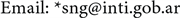
A parametric 3D CAD model has been created using OpenScad 2015.03-3 software. The design concept for this pyramidal absorber is based on the commercially available microwave absorber of TDKTM, type number is IS-030A. The sample of 3D model of PSA is shown in Figure 3.
The materials used for the PSA was produced by combining individual photopolymers offers by StratasysTM in specific concentrations and microstructures to create a composite material with absorbing properties. The acoustic properties of these materials are shown in Table 1. The velocity of sound was determined by time of flight technique using an ultrasonic echoscope Digital-Echograph 1090 of Karl Deutsch. This measurement was performed in reflection mode with 2 MHz probe Karl Deutsch S6WB2.25. The Attenuation of ultrasound was determined in reflection at the applied frequency of 2 MHz. The dimensions and weight of the test-samples were measured by a caliper and a digital scale, respectively.
The transmission coefficient between the two layers of the pyramid structure is equal to 0.987, which means that almost all the energy goes from the outer to the inner layer of the pyramid without reflection. So, the portion of the transmitted energy from the initial incident wave in the first layer (approx. 90%) can
Figure 3. Left: Pyramidal absorber 3D model. Right: 3D printed PSA using a Stratasys Objet500 Connex 3D printer. The internal structure of the pyramidal absorber is shown.

Table 1. Acoustic properties of digital composite materials produced and distilled water.
aStratasys rubber-like material: TangoBlackPlus FLX 980; bStratasys simulated polypropylene material: VeroClear-RGD810/TangoBlackPlus FLX 980.
be completely attenuated through the lossy material located inside the pyramid and the background plate.
A 10 × 10 array of PSA, with dimensions 94 mm × 94 mm × 28.2 mm and two homogeneous layers of different composite materials, has been printed using the Stratasys Objet500 Connex 3D printer. The coating thickness (SE) does not affect the external dimensions of the object, which remain unchanged. The coating layer replaces part of the main model material. Because the coating material thickness remains constant, if a part’s thickness is below ~0.8 mm, the core material will not be printed at all. The entire part will be printed using the coating material. The pyramidal shaped absorber must be larger compared to the longest wavelength so that the side to reflect the incident wave and the height of the pyramid must be greater than the half wavelength [8] . The dimensions of single pyramid of the designed absorber are shown in Table 2.
2.4. Reflection Loss Measurement
The frequency range investigated in this work is 0.5 MHz to 10 MHz. PSA performance is specified by echo reduction (ER) at normal incidence and is stated in dB. ER is defined as
(8)
where Pr is the acoustic pressure reflected from the sample, Pi is the acoustic pressure incident upon the sample, and zin and zwater are the input impedance at the front of the absorber and the acoustic impedance of water, respectively. This has been experimentally determined for a PSA sample in distilled water at 20˚C using the ultrasonic echoscope for frequencies of 0.5 MHz, 2 MHz and 8 MHz, as shown in Figure 4.

Figure 4. Reflection loss measurement setup. The acoustic pressure reflected as compared to that reflected from a 304-stainless-steel reference block. Left (a): The reference block has reflectivity of 0 dB down. The reference is the signal reflected from the surface of the reference block with the same area as the sample (not shown in the photo). The bottom plate has a reflectivity of −7 dB; Right (b): The sample of PSA reflects one fortieth of the energy which reflects the bottom plate.
Table 2. Dimension of pyramidal absorber.
2.5. Numerical Simulations
The simulation functions used in k-Wave require four input structures. These structures define the properties of the computational grid, the material properties of the medium, the properties and locations of any acoustic sources, and the properties and locations of the sensor points used to record the evolution of the pressure field over time [6] . Ultrasonic absorption in water, at a given temperature and frequency, was calculated using a 7th order polynomial fitted to the data given by Pinkerton [9] .
Simulations were performed in two-dimensions. To simulate free-field conditions, a perfectly matched layer (PML) is also applied as to absorb the waves at the edge of the computational domain [10] . By default, this layer occupies a strip of 20 grid points around the edge of the domain. Without this boundary layer, the computation of the spatial derivates via the FFT causes waves leaving one side of the domain to reappear at the opposite side. The use of PML thus facilitates infinite domain simulations without the need of an increase in the size of the computational grid.
The positioning of the transducer with normal incident field, each sensor point for the detection of the pressure field generated by incident pressure (Pi), reflected pressure (Pr) and transmitted pressure (Pt), and the visualisation of the computational model outputs are shown in Figure 5.

Figure 5. Up-Left: Normalized incident field of acoustic pressure at a frequency of 2 MHz for PSA with single homogeneous layer, and position of the individual sensor elements to record the acoustic pressures. Up-Right: Periodic structure of pyramidal shape cause diffracted waves and scattered waves. Down-Left: Ultrasound field is dissipated by the absorber for frequency 2 MHz. Down-right: Comparison of the incident, reflected and transmitted pressure fields.
Using both the simulated acoustic reflection and transmission pressure measurements shown in Figure 6, the insertion loss (IL) was calculated as
(9)
where Pt is the acoustic pressure transmitted through the sample and Pi is the acoustic pressure incident upon the sample.
The fractional power dissipation (FPD) is a parameter of an absorber material that quantifies its inherent dissipation of acoustic energy and is usually specified in commercial absorbers to compare the performance of different acoustic materials. The FPD has been derived from the ER and IL measurements and is defined by Precision Acoustics Ltd and Acoustic Polymers Ltd as
(10)
where Pr is the acoustic pressure reflected from the sample, Pt is the acoustic pressure transmitted through the sample and Pi is the acoustic pressure incident upon the sample. The FPD has been derived from the ER and IL measurements.

Figure 6. Simulated temporal signal of reflection and transmission for PSA with single homogeneous layer. Pi: Acoustic pressure incident upon the sample; Pt: Acoustic pressure transmitted through the sample; Pr: Acoustic pressure reflected from the sample.
3. Results and Discussion
Impedance gradient measurement were performed using the pulse echo method to determine the reflection loss performance of 7 test pieces of pyramidal absorbers printed with homogeneous material, over different portions of the material at the front face between top and ground of the pyramid. Figure 7 shows the experimental impedance gradient that the wave “sees” at different portions of the material, from the front face of the pyramid. The graph shows that impedance at the front face is very close to that of water but gradually increases at the back face.
Figure 8 shows the fabricated test tank using the printed PSA’s. In the frequency range of 0.5 MHz to 8 MHz, the reflectivity of the whole sample achieved at least −29.4 dB. At the frequency range of 0.5 MHz to 2 MHz it could achieve reflectivity beyond 38.9 dB down. The insertion loss is approximately 20 dB and the FPD is 99% between 0.5 MHZ to 2 MHz.
4. Conclusions
Our PSAs have been designed specifically for coating the walls of an ultrasonic test tank for a frequency range of 500 kHz to 5 MHz. Its simple design, which allows to create a 3D printed pyramidal array with specific microstructures built of composites materials, provides a cost-effective method of achieving high levels of echo reduction for custom solutions. A pyramidal wedge structure provides a smooth transition in acoustic impedance. Since there is no abrupt transition

Figure 7. Impedance gradient of the PSA. Since there is no abrupt transition layer, there is no point which will cause a large reflection.

Figure 8. Water tank coated to prevent unwanted reflections during medical ultrasonic measurements.
layer, no point causes a large reflection. This impedance gradient is a physical gradient: the wave “sees” a small portion of material at the front face and gradually an increasing portion as it travels into the material. This properties combination results in an absorber with impedance gradient that exhibits broadband reflectivity performance and high echo-reduction, >38 dB over frequency range 0.5 - 2 MHz, degrading to 29 dB at 8 MHz. Without the coating layer, the ER of the absorber was halved at 2 MHz.
In this study, the performance was predicted only at normal angle. The effects of incident directions to PSA are not considered. Also, for high power applications, significant temperature rises can be generated within the absorber material. The thermal tolerance for the measurement of High Intensity Therapeutic Ultrasound field is limited by the thermal performance of the materials used, as well as the exposure time. We will continue working to increase absorption and scattering effects by adding the top acoustic impedance matched layer and small inhomogeneities into the pyramidal layers, respectively.
Acknowledgements
This work was supported by the National Institute of Industrial Technology. The authors would like to acknowledge the 3D printing services provided by the Materialization Laboratory of the Industrial Design Center.
Cite this paper
Acquaticci, F., Yommi, M.M., Gwirc, S.N. and Lew, S.E. (2017) Rapid Prototyping of Pyramidal Structured Absorbers for Ultrasound. Open Journal of Acoustics, 7, 83-93. https://doi.org/10.4236/oja.2017.73008
References
- 1. Preston, R.C. (1991) Output Measurements for Medical Ultrasound. Springer-verlag, Germany. https://doi.org/10.1007/978-1-4471-1883-1
- 2. Aoyagi, T., Kurihara, H., Takizawa, K. and Hirai, Y. (2014) Effects of Incident Directions on Reflection Coefficients of Pyramidal Electromagnetic Wave Absorber. EMC’14, Tokyo.
- 3. Holloway, C.L., German, R.F., McKenna, P. and Kanda, M. (1997) Comparison of Electromagnetic Absorber Used in Anechoic and Semi-Anechoic Chambers for Emissions and Immunity Testing of Digital Devices. IEEE Transactions on Electromagnetic Compatibility, 39, No. 1. https://doi.org/10.1109/15.554693
- 4. Khajehpour, A. and Mirtaheri, S.A. (2008) Analysis of Pyramid EM Wave Absorber by FDTD Method and Comparing with Capacitance and Homogenization Methods. Progress in Electromagnetics Research, 3, 123-131. https://doi.org/10.2528/PIERL08021802
- 5. Iqbal, M.N., et al. (2013) A Simple Technique for Improving the Anechoic Performance of a Pyramidal Absorber. Progress in Electromagnetics Research, 32, 129-143. https://doi.org/10.2528/PIERM13061607
- 6. Treeby, B.E. and Cox, B.T. (2010) k-Wave: MATLAB Toolbox for the Simulation and Reconstruction of Photoacoustic Wave-Fields. Journal of Biomedical Optics, 15, 021314. https://doi.org/10.1117/1.3360308
- 7. Kinsler, L.E., Frey, A.R., Coppens, A.B. and Sanders, J.V. (2009) Fundamentals of Acoustics. 4th Edition, John Wiley & Sons Ltd., New York.
- 8. Imran, M.I., Abd Aziz, M.Z.A., Ja’far A.S., Hashim, A., Azremi, A.A. and Soh, P.J. (2008) On the Design, Fabrication and Measurement of Microwave Absorbers. Proceeding of Malaysian Technical Universities Conference on Engineering and Technology, Putra Palace, Kangar, 15-16 March 2008.
- 9. Pinkerton, J.M.M. (1949) The Absorption of Ultrasonic Waves in Liquids and Its Relation to Molecular Constitution. Proceedings of the Physical Society, Section B, 2, 129-141. https://doi.org/10.1088/0370-1301/62/2/307
- 10. Katsibas, T.K. and Antonopoulos, C.S. (2004) A General Form of Perfectly Matched Layers for Three-Dimensional Problems of Acoustic Scattering in Lossless and Lossy Fluid Media. IEEE Transactions on Ultrasonics, Ferroelectrics and Frequency Control, 51, 964-972. https://doi.org/10.1109/TUFFC.2004.1324400