World Journal of Engineering and Technology
Vol.02 No.03(2014), Article ID:48475,8 pages
10.4236/wjet.2014.23021
Experimental Evaluation of the Attenuation Effect of a Passive Damper on a Road Vehicle Bumper
A. Agyei-Agyemang1, G. Y. Obeng2, P. Y. Andoh1
1Department of Mechanical Engineering, College of Engineering, Kwame Nkrumah University of Science and Technology (KNUST), Kumasi, Ghana
2Technology Consultancy Centre, College of Engineering, Kwame Nkrumah University of Science and Technology (KNUST), Kumasi, Ghana
Email: tonyagyemang@yahoo.com, geo_yaw@yahoo.com, andohp_2@yahoo.com
Copyright © 2014 by authors and Scientific Research Publishing Inc.
This work is licensed under the Creative Commons Attribution International License (CC BY).
http://creativecommons.org/licenses/by/4.0/


Received 27 May 2014; revised 12 July 2014; accepted 27 July 2014
ABSTRACT
To mitigate the degree of damage to passengers caused by automobile collisions, a friction damper was built and used in experimental tests to test its effectiveness in impact energy attenuation. The study revealed that energy absorption capacity of a bumper can be improved with the addition of a friction damper. The results revealed that the addition of the friction damper to an automobile bumper to give a bumper-damper system could attenuate about 32.5 % more energy than with the bumper alone. It can be concluded that the effectiveness of automobile bumpers to withstand impact of vehicles by absorbing the kinetic energy from the impact can be improved with the use of a passive friction damper. That is, a passive friction damper system could be used to attenuate more road vehicle impact energy in collisions.
Keywords:
Vehicle Bumper, Equivalent Energy Speed (EES), Impact Attenuation, Passive Damper

1. Introduction
Road traffic crashes and their effects are quite complicated and expensive. Costs attributable to this include social costs, medical costs, loss of production, human costs, material costs, settlement costs and traffic jam costs. Road traffic accident costs Ghana US$ 165 million annually, which is about 1.6% of its Gross Domestic Product (GDP) [1] . Appiah [2] estimates that about 4 people get killed daily and there are 1600 fatalities annually in Ghana. Road crashes worldwide cost about US$ 518 billion and claim about a million lives worldwide every year; research suggests that if steps are not taken to change the trend, road traffic injuries will be the third leading cause of death by the year 2020 [3] . Even though injuries in some crashes are not very severe, yet front to rear crashes between vehicles at low speeds (speeds well below 32 km/h) account for a large number of significant injuries usually classified as Whiplash Associated Disorders (WAD) [4] . Hoover [5] , reports that whiplash is the most common automobile injury, yet it is poorly understood. The bumper plays a very important role in managing the effect of crashes at low speeds. The bumper design is therefore very important.
Over the past 20 to 30 years, Bumper design concepts have changed drastically. EEA [6] describes four basic bumper design principles (Where necessary, specific features can also be combined). They are: First, the traditional design with a visible metallic transverse beam that decorates the front or rear end of the vehicle and acts as the primary energy absorber during collision; which is seldom used today. Secondly, the plastic fascia and reinforcing beam system that is fixed directly to the front/rear longitudinal beams. This design increases the overall vehicle crashworthiness but leads to a small sacrifice in bumper performance. Thirdly, the system consisting of three components: a plastic fascia, a reinforcing beam and mechanical energy absorbers. The energy absorbers come in two types. They may be either of a reversible type (“shock absorbers”) or deformation elements (“crash boxes”) which are usually replaced after a crash. Lastly, a system, which is more pedestrian friendly in leg impact, which includes a plastic fascia, a reinforcing beam and a propylene foam or a honeycomb energy absorber placed between the plastic fascias and reinforcing beam.
An automobile bumper is the front-most or rear-most part, specially designed to allow the car to sustain low speed impact without damage to the vehicle’s safety systems. That is, they are not capable of reducing injury to vehicle occupants in high speed impacts [7] [8] . It is required to pass an impact test at 4 km/h (2.5 mph) with no visible damage to the body. Bumpers keep safety-related equipment such as headlights and taillights, hoods, fenders, exhaust and cooling systems, away from damage. Some bumper designs have the provision of cushioning and support of the lower limb; as well as the integration of impact sensors and exterior airbags [9] . The main method proposed for cushioning the lower limb in an impact uses an energy absorber in front of a semi-rigid beam. Energy absorbers proposed include plastic foams (single or multi-density), molded plastic “egg-crates”, “spring-steel”, composite steel-foam, and crush-can energy absorbers [9] . Exposed steel bumpers that involve frontal airbags design are also alternative design concepts that appear to be adaptable to meet the pedestrian’s safety requirements but these may be costly and require advanced sensors to function efficiently [9] .
For passenger cars in USA, the law specifies 10 bumper tests, including pendulum tests and crashes into a fixed flat barrier. This is in line with the bumper standards that stipulate the impact resistance of vehicles in low speed front and rear collisions. The purpose of the Bumper standard for Passenger Motor Vehicles other than Multipurpose Passenger Vehicles was to reduce physical damage to the front and rear ends of a passenger motor vehicle from low speed collisions [10] [11] . Bumpers are tested using pendulum and fixed barrier tests. Apart from pendulum tests at 2.4 km/h (1.5 mph), bumpers must pass the fixed barrier tests. The fronts and rears of the vehicles crash into a flat barrier at 4 km/h (2.5 mph). To pass these barrier and pendulum tests, unlimited damage is allowed to the bumper, but none is allowed to other parts of the vehicle. Hood and trunk doors, propulsion, suspension, steering, and braking systems must all operate normally after the test. There should be no broken headlights or fuel, cooling, or exhaust leaks or constrictions after the tests. The bumper should be within the test zone of 40.64 to 50.8 cm (16 - 20 inches) from the ground. SUVs and vans are excluded from such bumper standards. Even though most pickups and SUVs do have bumpers, their heights often vary from the USA federally specified test zone for cars.
Bumpers could be designed to absorb more energy than they usually do with some modification of the design and possibly with the use of additional energy absorption devices. This work seeks to apply a passive control system which is an uncontrolled damper that requires no input power to operate. Passive control systems attenuate or absorb vibrations automatically without the need of an electrical control system. They are simple and generally low in cost, but are unable to adapt to changing needs after installation. The passive control system was selected for this work because of its stability, simplicity and low cost in its application. Passive systems include base isolation systems, viscoelastic dampers, bracing systems and friction dampers [12] . Base isolation systems are used to isolate the dynamic force transfer from the structure to the base. Viscoelastic dampers attenuate the force due to external loads using their natural damping properties. Bracing systems are usually made up of brace frames and are usually used to permanently stabilize buildings from external forces such as wind loads and earthquakes by stiffening the structural components; and lastly friction elements consist of dampers that use dry friction to dissipate energy. They are also referred to as Coulomb Damping Systems. Witteman [13] suggested the use of friction to absorb kinetic energy in crash situations by regulating the amount of pressure or normal force on the friction element. The friction element was selected for this study because it does not need external energy, it is robust, and low cost. Even though viscous damping shares most of these advantages, the friction damper’s dryness and therefore no risk of leakages during operation makes it preferable. Although using friction to absorb energy has a big potential, little has been done to exploit it in attenuating crash energy.
Figure 1 shows that, males of age 15 to 44 years are more likely to be involved in road traffic crashes than females. Most breadwinners of families and communities are males in the developing world. Since about 90% of all traffic deaths occur in the developing world, and the majority of these victims are in their most productive years, road crashes are taking a big toll on the livelihood at majority of people on earth [3] . This is a cause for concern that needs to be addressed.
King et al. [14] reported that bumper systems on passenger cars available in North America, though built to meet specific government standards, had different impact characteristics among different vehicles and that certain vehicles could sustain significant front or rear impacts without sustaining damage. There have been efforts to improve on the energy absorption capacity of the bumper. For example, bumper isolators are shock absorbers that are mounted between the vehicle frame and bumper, and are specially designed to reduce an amount of property damage to vehicles [15] . Impact attenuation has been investigated by different people using different methods over several years. Grassie [16] [17] investigated the dynamic load attenuation by rail pads in laboratory and on track. Esveld [18] claims that ballasted railway track had many superior advantages.
By using stiffness of a vehicle and its components, the kinetic energy loss in deformation on vehicles can be estimated. In an investigation, Vangi [19] estimated the stiffness of a vehicle by estimating the geometric parameters of the damage starting from a photograph of generic damage, with documented Equivalent Energy Speed (EES), on a vehicle of the same model as the one under investigation. This method was validated performing crash tests and using data from crash tests found in the literature. The method estimated the kinetic energy loss in deformation on vehicles with sufficient accuracy [19] .
Different impact attenuation measures have been used in the railway industry, for example, to mitigate the effect of high forces on the sleeper. In one of such examples, the force content is filtered and attenuated by the softening medium, rail pad installed between sleeper and rail [20] . Similar measures can be introduced in the automobile bumper system to improve its mitigation of high impact forces at higher speeds. Kaewunruen and Remennikov [21] , in their test to find the effect of impact loads on railway seats, used a drop hammer and a specially designed fixture to transfer the impact load to the specimens. This study aims at helping to solve part of this serious problem through the development of a more effective crash attenuation system. Hence, the objective of this work is to find out experimentally, whether the addition of a passive damper to a road vehicle bumper could improve its impact energy absorption capability.

Figure 1. Global road traffic fatalities by sex and age (Source: [3] ).
2. Material and Method
An experiment was performed using an impact test machine to investigate whether the impact attenuation capacity of a bumper could be enhanced with the addition of a friction damper. A model of friction damper was designed using springs with a definite stiffness. Special fixtures were made to adapt the impact test machine to the test conditions. Fixtures were fastened to the hammer and machine to give a good surface for the impact. The impact fixture was made in the shape of an L, with webs to strengthen the welded joints. This was clamped to the impact machine as shown in the schematic diagram in Figure 2.
During the experiment, the bumper specimen and the bumper-damper combination, where applicable, were arranged together and the hammer of the impact machine allowed swinging freely to impact on it. The hammer of the impact test machine was raised to specific heights and allowed to fall under gravity to hit the bumper specimen in the experimental setup. During the experiments four different heights were used to give four impact forces.
The angle at which the hammer swings from rest,
 , and the angle at which it impacts the test specimen,
 , were measured and noted. The angle is as indicated in the schematic diagram in Figure 3. The deformation on the bumper specimen after the impact was measured with a veneer caliper and noted.
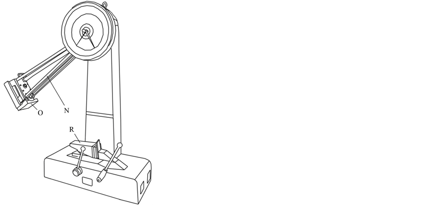
Figure 2. Impact test machine with impact (R) and hammer (O) fixtures.

Figure 3. Schematic of a simplified pendulum hammer of an impact test machine.
Destructive impact tests were performed on pieces of the bumper specimen. Specimen from two bumpers B and C, from two different cars were used in the analysis. 4 specimens of bumper B and 8 specimens of bumper C were used. The average length of the specimen was 35 cm. The specimen, and where applicable both specimen and damper, were put together, placed on the impact fixture and the hammer allowed to swing freely to impact on it/them.
The friction damper was made with springs of stiffness 44 kN/m. For bumper B, the four bumpers were tested without a friction damper; but for bumper C, four specimens were tested without a damper, and four tested with a damper. The impact forces during the tests were computed and used in the analysis. The results obtained for the two sets of tests are tabulated and presented in Table 1. Bumper B, tested without a damper, was to help establish whether bumper C without a friction element will follow a similar trend. It can be observed that for both bumper samples, results increase steadily with increase in impact load in a linear way. However, the deformation in bumper C is much higher than that of bumper B for the same impact forces. This may be due to the different material properties in the different bumpers. When a friction element was added, in the case of bumper C, the same forces as used in the previous tests, where no friction element was added, could not be used. The now shorter distance of travel of the pendulum to impact on the Bumper-Damper arrangement would not allow the same impact forces to be used. The results show that with increase in impact forces, the deformation starts increasing very slightly at first but at the higher impact force of 9078.95 N it increases drastically from 9 mm (for 7438.27 N) to 27 mm, showing an exponential trend. Curve-fitting method was used to present the curves of the experimental results as described in the next section.
3. Analysis of Results
Consider a hammer swings through an angle, θ before impact, as indicated in Figure 3.
Then, the sum of moments at point A is given by

This implies

Hence

But

Then

But ω1 = 0, since the hammer swings from rest.
Therefore

Table 1. Experimental results for the two sets of tests.

Therefore,

Also,

Hence the impact force F from the pendulum is
 (1)
(1)
Hence Equation (1) gives the impact force, F, from the pendulum swinging through the angle .
.
Therefore the maximum impact force, F, from the pendulum is when

Using the following values for the machine, for a hammer of mass of 20 kg;
 of 0.9868 m; time of 0.2 s; acceleration due to gravity of 9.81 m/s2 and moment of inertia of 0.0453 m4, then the maximum impact force F from the pendulum was obtained as 9123.5 N. In a similar way, four impact forces were calculated, using Equation 1 for different impact angles,
 , given in Table 2.
4. Discussion of Results
4.1. Impact Forces
Using the Equation (1), different angles,
 , the impact forces were computed. The impact forces are presented in Table 2.
These results were used to determine the energy absorbed in the impact by plotting a graph of Impact force against deformation and finding the area under the curve. The details are given in the next section.
4.2. Energy Absorbed
The strain energy absorbed can be calculated by plotting a graph of impact force versus deformation and using integration method to find the area under the curve. The impact forces and their respective deformations were plotted and curves fitted to the plots. MATLABTM was used to find the best fitting curves and their equations. It was observed that the curves had a general equation of the form:

Table 2. Angle of pendelum hammer and corresponding impact forces.
where y is the displacement and x is the impact force ´ 10−5; and A, B and C are constants. That is Displacement = A(Impact force ´ 10−5) + B(ln(Impact force ´ 10−5)) + C. Equations of the curves are also given in Table 3.
Plots of the curves of the experimental results are presented in Figure 4 and Figure 5. The result of bumper B without a friction damper as shown in Figure 4 is linear. The results show a curve-fitted relationship that is very close to a linear one. This may be due to experimental imperfections.
The results of bumper C with a damper give an exponential curve shown in Figure 5(b). In these tests, the damper stuck and did not slide. The results obeyed the relationship y = Ax +Blnx + C after curve-fitting; where y is the deformation and x is the impact force ´ 10−5. The results of the tests for bumper C, with and without a friction damper, were plotted as shown in Figure 5(a) and Figure 5(b) and used to calculate for the strain energies absorbed by the bumper in both tests.
The amount of energy absorbed in each case (with or without a damper) for a deformation of 2.5 cm was calculated. The strain energy absorbed as a result of the deformation of the bumper is given by the areas under the respective curves. From Figure 5(a) and Figure5(b), for a deformation of 2.5 cm, the energy absorbed by the bumper without the friction damper is given by the area ABIH (see Figure 5(a)). The energy absorbed as a result of the same amount of deformation when the friction damper is used is given by area ACIH (see Figure 5(b)).
The areas were calculated using integration of the equations of the respective curves.

From the calculations, energy absorbed by the bumper without a friction damper was 119.42 J, and that absorbed by the bumper C with friction damper was 158.22 J. This implies that the bumper-damper system absorbed 38.8 J more energy than that without the friction damper. This represent 32.5% more energy for the one with the friction damper than the one without the friction damper.
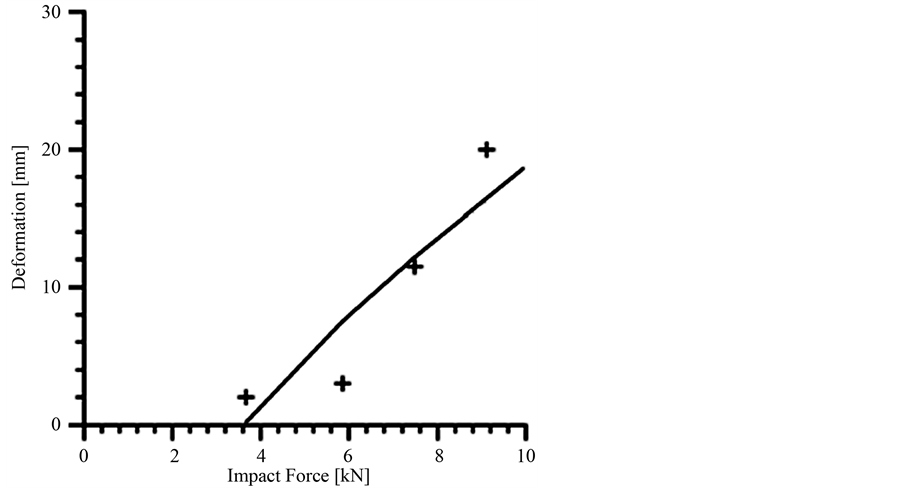
Figure 4. Results for bumper B without a friction element.
Table 3. Curve-fitted equations of the deformation for different impact forces for the different specimen.
 (a)
(a) (b)
(b)
Figure 5. Results for bumper C with (b) and without (a) a Dam- per.
5. Conclusion
A friction damper was built and tested with a bumper to check for its effectiveness to attenuate impact energy. The study showed that energy absorption capacity of a bumper can be improved with the addition of a friction damper. The experimental results revealed that the addition of the friction damper to a bumper to give a bumper- damper system could attenuate about 32.5% more energy than with the bumper alone. It can be concluded that the effectiveness of automobile bumpers to withstand impact of vehicles by absorbing the kinetic energy from the impact can be improved with the use of a friction damper.
6. Sources of Error
The method used for the experiment was a destructive one therefore each specimen could be used only once. Since material manufacturing methods cannot guarantee that the material strictly had the same properties, deviation of material property in the same bumper could also have affected the experimental results. This could also have influenced the experimental results.
References
- BRRI (2006) Estimation of Cost of Road Traffic Accidents in Ghana.
- Appiah, N.J. (2009) Implementing a Decade of Action in Africa: Examples of Road Safety Interventions. National Road Safety Commission, Ghana. Proceedings of the Make Roads Safe Conference, Dares Salaam, 8-10 July 2009.
- Peden, M., Scurfield, R., Sleet, D., Mohan, D., Hyder, A.A., Jarawan, E. and Mathers, C. (2004) World Report on Road Traffic Injury Prevention. World Health Organization, Geneva.
- Brach, M.R. (2003) Modelling of Low Speed, Front-to-Rear Vehicle Impacts. Society of Automotive Engineers. https://www.brachengineering.com/content/publications/SAE-2003-01-0491-Brach-Engineering.pdf
- Hoover, J. (2012) Dynamic Analysis of Whiplash; Mechanical and Industrial Engineering. University of Toronto. https://tspace.library.utoronto.ca/bitstream/1807/32245/3/Hoover_Jeffery_BL_20123_MASc_thesis.pdf
- European Aluminium Association (EAA) (2013) The Aluminium Automotive Manual. Applications-Car Body-Crash Management Systems. http://www.alueurope.eu/wp-content/uploads/2011/12/4_AAM_Crash-management-systems1.pdf
- Uddandapu Pradeep Kumar (2013) Impact Analysis on Car Bumper by Varying Speeds Using Materials ABS Plastic and Poly Ether Imide by Finite Element Analysis Software Solid Works. International Journal of Modern Engineering Research (IJMER), 3, 391-395
- Tomar, M. and Chakraborty, A. (2013) Design of Bumper as a Collision Energy Absorbing System. International Journal of Engineering Research and Applications, 3, 115-118.
- Schuster, P. (2004). Current Trends in Bumper Design for Pedestrian Impact: A Review of Design Concepts from Literature and Patents. Bumper Project, The American Iron and Steel Institute.
- FMVSS (1999) Federal Motor Vehicle Safety Standards and Regulations. U.S. Department of Transportation. http://www.nhtsa.gov/cars/rules/import/FMVSS/index.html#P581
- NHTSA (1977) Bumper Standard, Title 49 Code of Federal Regulations Part 581. Washington DC, 49.
- Lametrie, C.W. (2001) A Literary Review of Structural Control: Earthquake Forces. Parksons Brinckerhoff Automotive Division, Warren, Michigan.
- Witteman, W. (2005) Adaptive Frontal Structure Design to Achieve Optimal Deceleration Pulses, Mechanics of Materials/Vehicle Safety, Technische Universiteit Eindhoven, The Netherlands, Paper Number 05-0243. http://www-nrd.nhtsa.dot.gov/pdf/ESV/esv19/05-0243-O.pdf
- King, D.J., Siegmund, G.P. and Bailey, M.N. (1993) Automobile Bumper Behaviour in Low-Speed Impacts. SAE Technical Paper Series, Society of Automotive Engineers. http://trid.trb.org/view.aspx?id=382198
- Arthur, C. (1999) Practical Auto Crash Considerations in LOSRIC, Part III. Dynamic Chiropractic, 17.
- Grassie, S.L. (1987) Measurement and Attenuation of Load in Concrete Sleepers. Proceedings of Conference on Railway Engineering, Perth, 14-16 September 1987, 125-130.
- Grassie, S.L. (1989) Resilient Rail Pads: Their Dynamic Behaviour in the Laboratory and on Track. Journal of Rail and Rapid Transit, 203, 25-32. http://dx.doi.org/10.1243/PIME_PROC_1989_203_205_02
- Esveld, C. (2001) Modern Railway Track. 2nd Edition, MRT-Productions, The Netherlands.
- Vangi, D. (2009) Simplified Method for Evaluating Energy Loss in Vehicle Collisions. Accident Analysis and Prevention, 41, 633-641.
- Kaewunruen, S. and Remennikov, A.M. (2007) Experimental Simulation of Railway Ballast in Laboratory and Its Verification Using Modal Testing, Experimental Techniques. (in Press)
- Kaewunruen, S. and Remennikov, A.M (2008) An Experimental Evaluation of the Attenuation Effect of Rail Pad on Flexural Behaviour of Railway Concrete Sleeper under Severe Impact Loads. Proceedings of Conference Australasian Structural Engineering Conference (ASEC), Melbourne, 2008, 522-531.