Open Journal of Microphysics
Vol.3 No.3(2013), Article ID:35756,10 pages DOI:10.4236/ojm.2013.33013
Photons Are EM Energy Superpositioned on TEM Waves
Uppsa Research, Gnesta, Sweden
Email: hans@miklagaard.com
Copyright © 2013 Hans W. Giertz. This is an open access article distributed under the Creative Commons Attribution License, which permits unrestricted use, distribution, and reproduction in any medium, provided the original work is properly cited.
Received April 24, 2013; revised May 24, 2013; accepted June 2, 2013
Keywords: Photon; TEM Wave; Wave-Particle Duality; Elementary Particle; Light Wave
ABSTRACT
The study displays that TEM waves (e.g. radio waves, light) consist of low frequency plane TEM waves where the radio frequency energy or light energy is superpositioned on these low frequency TEM waves. The superpositioned energy can be discrete and where its frequency ν determines its energy hv and where this superpositioned energy hv is the photon. The study shows that photons and TEM waves are described by the laws of electromagnetism. Hence, there is a duality between the photon and the TEM wave and also a duality between electromagnetism and quantum theory in this case. The low frequency plane TEM waves originate from a singularity in universe and have been described earlier. The study describes how energy from a generator, from light bulbs and radio antennas is superpositioned on low frequency TEM waves, resulting in medium frequency TEM waves, radio waves and light. The study displays that light from the sun consists of light energy superpositioned on low frequency TEM waves. The study describes methods enabling measurement of the low frequency plane TEM waves and the superpositioned energy.
1. Introduction
The photon propagates with the velocity of light in free space because it has zero charge and zero mass [1-4]. It is known that the photon has spin angular momentum and helicity [5-7]. The photon exhibits both wave like properties and particle like properties [8,9]. In the radio frequency domain the wave is normally a plane TEM (transverse electromagnetic) wave, described by Maxwell’s equations [10,11]. Light is described by its photon and its circular polarized TEM wave. However, the relationship between photon and TEM wave is far from obvious. State of the art physics offers little explanation to why the photon has zero charge and mass and why it has momentum, spin angular momentum and energy [12]. The conclusion is that state of the art physics is incapable of describing a theoretical model of the photon and its relation to the TEM wave.
The present study builds on a novel way to measure extremely low frequency plane TEM waves, allowing unbundling of the wave into its individual field vectors and where superpositioned energy can be measured separated from the TEM wave [13].
It has been reported [14] that the universe contains a gravitational singularity called Energy Source, oriented to the north and aligned approximately in direction of the earth’s rotational axis. The Energy Source comprises a gigantic generator emitting vast amount of extremely low frequency plane TEM waves with frequency 69.9 Hz and 91.9. In the present study only the influence from 69.9 Hz is included, in order to simplify the description. These TEM waves are called gravity waves in the present study.
In the present study the hypothesis is that radio waves and light waves are radioor light-EM (electromagnetic) energy superpositioned on gravity waves. The photon is a discrete package of EM energy superpositioned on gravity waves and where the sum of many superpositioned photons is a light wave.
Section 2 encompasses the theoretical model which describes how e.g. radio transmitter EM energy and light source photon EM energy is superpositioned on 69.9 Hz gravity waves. The theoretical model was compared with acknowledged characteristics of photons.
Section 3 describes measurement methods. TEM waves in the 100 Hz range cannot be measured using state of the art instruments and methods. A novel technique must be used and this section describes both instrument and methods in detail.
Section 4 includes results, where the purpose is to prove the theoretical model. Low frequency EM energy from a signal generator, radio transmitter EM energy and light source photon EM energy was superpositioned on gravity waves. The superpositioned EM energy was measured separated from the gravity wave energy. The superpositioned light photon EM energy was removed from light waves, displaying that the light wave was converted back to a gravity wave (69.9 Hz). The superpositioned EM energy’s amplitude and frequency was changed and the resulting TEM wave energy was measured and compared with the theoretical model.
Section 5 covers discussion and Section 6 covers conclusions.
Novelty: According to state of the art physics radio and light TEM waves are created by radio transmitter EM energy or light source energy. The photon is a particle but its relation to the TEM wave cannot be explained based on today’s understanding. The novelty in the present study is a fundamentally new description of these processes. Low frequency TEM waves are generated by a singularity in the universe and accessible everywhere. The radio or light EM energy is superpositioned on existing low frequency TEM waves (gravity waves). The photon is a discrete package of EM energy superpositioned on low frequency TEM waves. The novelty in the present study is also that it describes (theoretically) the duality between wave and photon and a duality between electromagnetic theory and quantum theory.
The aim of the study is to present and to verify a theoretical model of the photon and its relation to TEM waves in e.g. light and radio waves.
2. Theoretical Model of the Photon
The amplitude of light and radio waves decreases linearly with the distance r from the source (as 1/r). The density of any type of uniformly distributed physical particle decreases with the square of the distance r from the source (as 1/r2), else the particle must multiply itself which is, of course, impossible. Hence, it is unlikely that the photon is a particle. The only known phenomenon in physics which decreases linearly with distance is the far field from accelerated charge, e.g. the plane TEM wave according to Maxwell’s equations [10,11]:
 (1)
(1)
 (2)
(2)
The theory of energy transport in space can be illustrated with radio waves. According to state of the art science radio waves are the result of accelerated electrons in the antenna which generate a far field according to Equations (1) and (2), and where this far field is a plane TEM wave. This TEM wave can be absorbed (e.g. in matter or receiver antenna) whereby its energy is dissipated as e.g. heat or current in the antenna and which results in that the TEM wave ceases to exist.
The real process is very different; however, the end result is almost the same. A singularity in universe, called Energy Source, generates enormous amounts of plane TEM waves 1, see Figure 1. They have extremely low frequency 69.9 Hz and are generated according to Equations (1) and (2) [14]. The TEM wave is called gravity wave in the present study. The theory of gravity has been reported [14].
The atom contains intrinsic electric dipoles 2 and 3. They create resonance with gravity waves and re-emit the waves unaltered. Some re-emitted gravity waves from 2 propagate to another atom and one of its dipoles 3. Simultaneously there is a flow of gravity waves from 1 to 3 and then to 2. The flow of gravity waves between two dipoles creates mutual force of attraction, i.e. gravity [14].
The energy, with frequency ν, in a radio transmitter accelerates electrons, see Figure 2. The electron consists of a configuration of dipoles and where they create resonance with gravity waves. Each dipole has energy caused by electron acceleration with frequency ν. The dipole superpositions this energy on gravity waves 4. This results in radio waves with frequency ν + 69.9 Hz. The radio wave is a plane TEM wave and its amplitude is proportional to the number of involved dipoles and that is proportional to the number of involved electrons, i.e. the antenna current. The process can be regarded as continuous. The radio wave can be absorbed in matter 5 and where the superpositioned energy with frequency ν is absorbed resulting in that the radio wave is converted back to the original gravity wave with frequency 69.9 Hz.
It is proposed that photons are the result of time limited processes, e.g. deceleration of an electron or by the
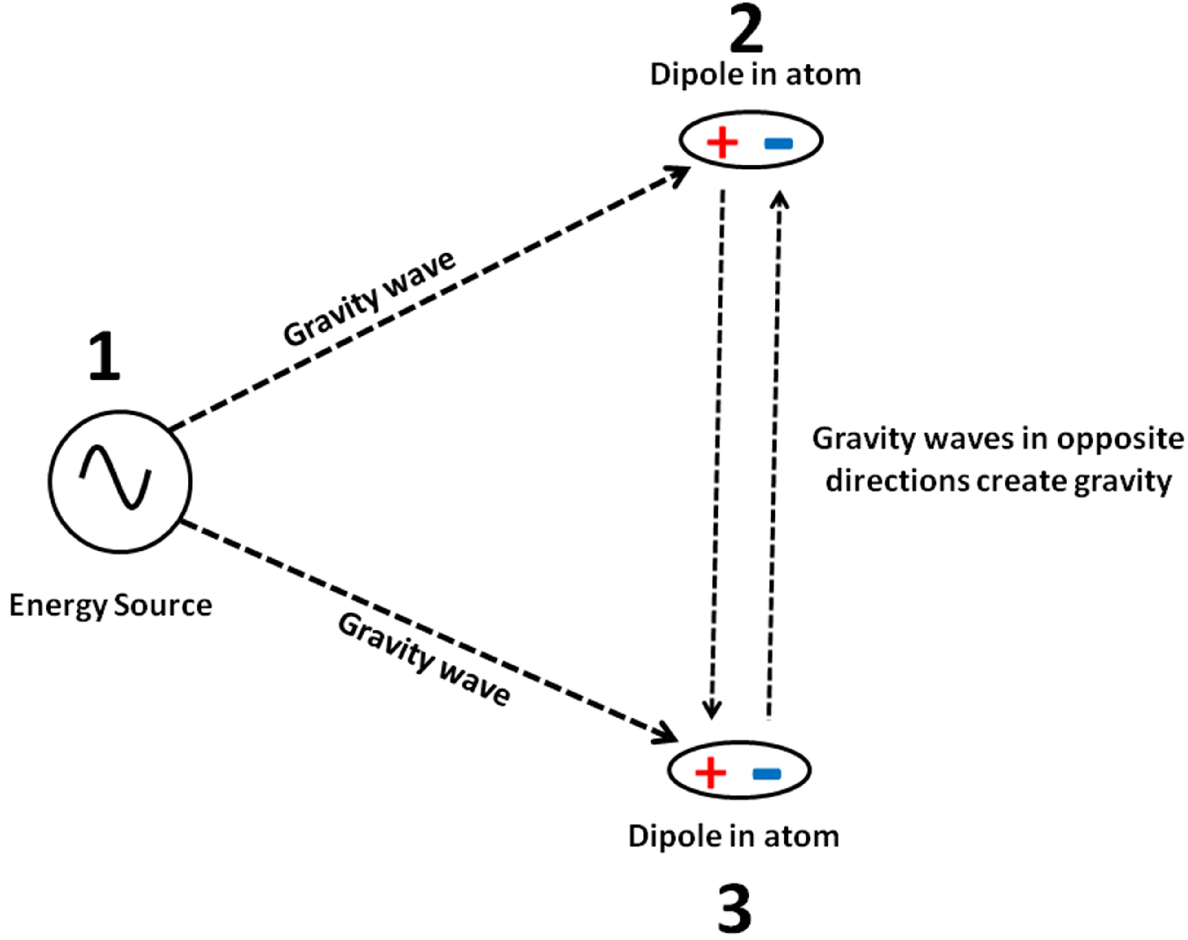
Figure 1. A gravitational singularity 1 generates gravity waves (low frequency plane TEM waves). Dipoles 2 and 3 in atoms create resonance with gravity waves and re-emit them unaltered. This causes flow of gravity waves between atoms and their dipoles 2 and 3. The flow of gravity waves in opposite directions between dipoles results in mutual force of attraction, i.e. gravity.
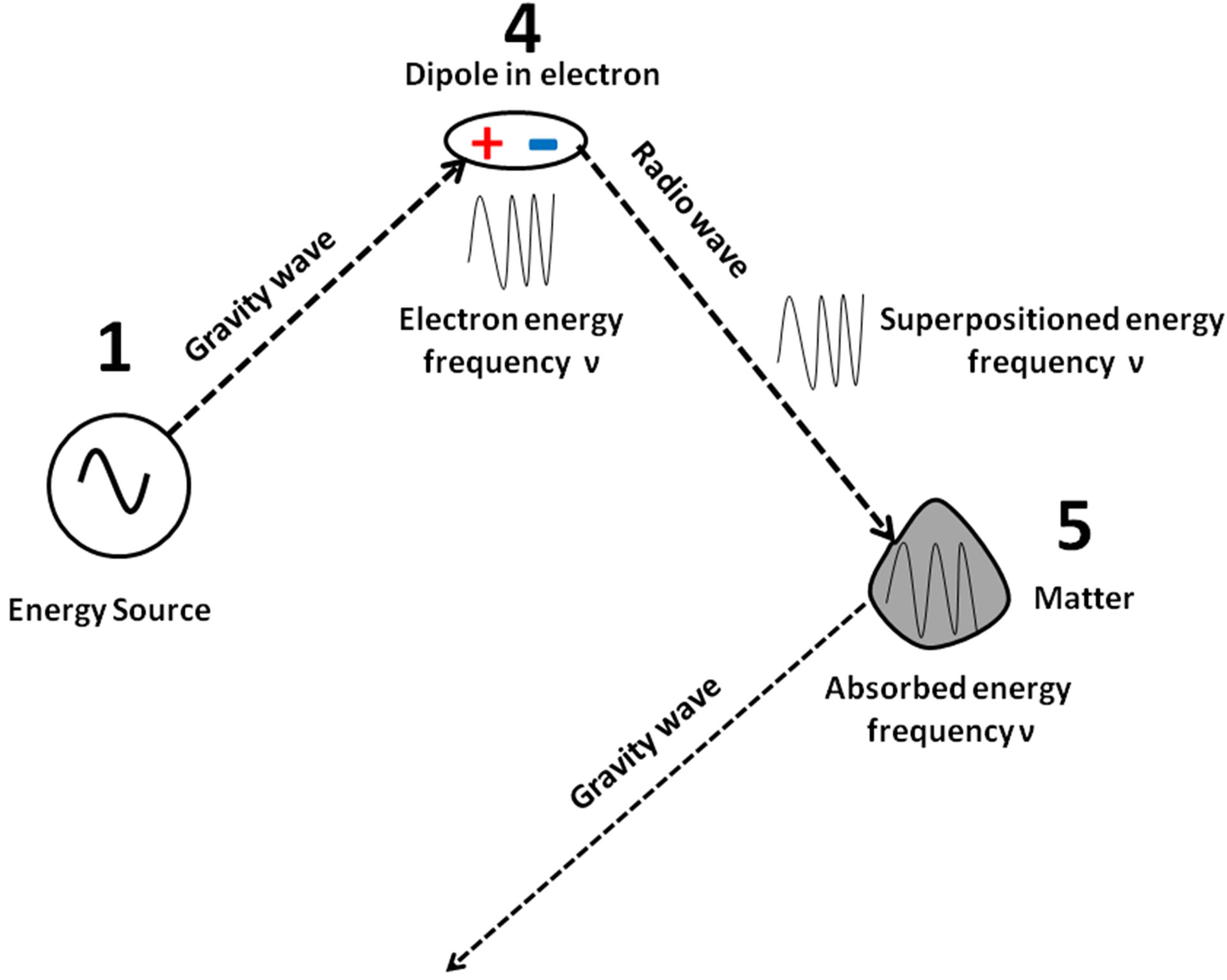
Figure 2. Electrons in the radio antenna are accelerated with the radio frequency ν. The electron contains a dipole. The dipole 4 in an electron creates resonance with gravity waves and the energy with frequency ν is superpositioned on these gravity waves. The resulting waves with frequency v + 69.9 Hz are re-emitted as radio waves. The superpositioned energy can be absorbed in matter 5, whereby the radio wave is converted into the original gravity wave with frequency 69.9 Hz.
decay of high energy atomic nucleus, see Figure 3. In this case the dipole 6 in the electron or the atomic nucleus contains the energy package hν where h is Planck constant or quantum of action. The energy package hν is discrete and limited in time. The energy package hν is superpositioned on the gravity wave and results in a TEM wave with frequency 69.9 Hz and instant ν. The sum of many photons and their energy hν results in e.g. a light wave and where the wave’s amplitude is proportional to the number of photons. The superpositioned energy is often circular polarized and can circulate righthanded or left-handed [15,16]. The light wave can be absorbed in matter 7 and where the superpositioned energy hν is absorbed resulting in that the light wave is converted back to the original gravity wave with frequency 69.9 Hz.
The energy contained in a TEM wave is proportional to its frequency ν. From this follows that the superpositioned energy and the photon energy δE is:
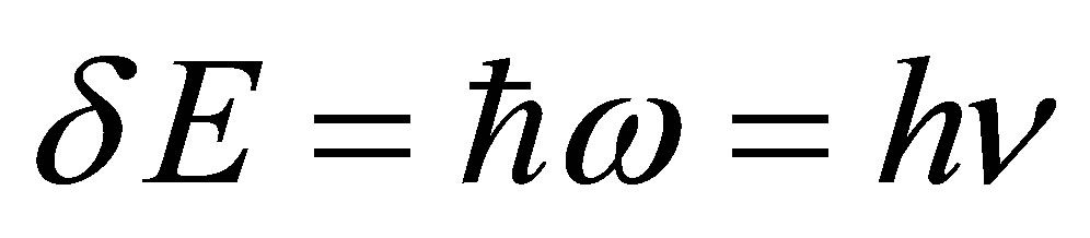 . (3)
. (3)
In empty space, the TEM wave propagates at the speed of light c. The TEM wave’s superpositioned energy and momentum are related as δE = pc, where p is the magnitude of the momentum vector p. This derives from the following relativistic relation, with m = 0 [1]:
 (4)
(4)
 (5)
(5)
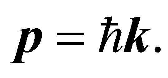
where k is the wave vector (where the wave number k = |k| = 2πν/c), and ħ = h/2π is the reduced Planck constant. Since p points in the direction of the TEM wave propagation, the magnitude of the momentum is:
 . (6)
. (6)
The photon also carries spin angular momentum that does not depend on its frequency v. The magnitude of its spin is  and the component measured along its direction of motion, its helicity, is ±ħ. These two possible helicities, called right-handed and left-handed, correspond to the two possible circular polarization states of the photon [5-7] and as described above.
Thus the photon is not a particle; however, discrete energy hν superpositioned on a TEM wave. From this follows that the photon is strictly mass less, has zero charge and propagates with the speed of the TEM wave, i.e. with the speed of light in free space. It also explains the wave-particle duality and which is really not duality but the principle of superposition.
In this case there is a duality between electromagnetism and quantum theory.
3. Materials and Methods
Experiments 1-4 were performed almost identical to experiments described previously [14]. Experiments 1-3 were performed using two identical devices, i.e. two electric dipoles called ED.
The ED created resonance with gravity waves, i.e. plane TEM waves with frequency 69.9 Hz. They originated
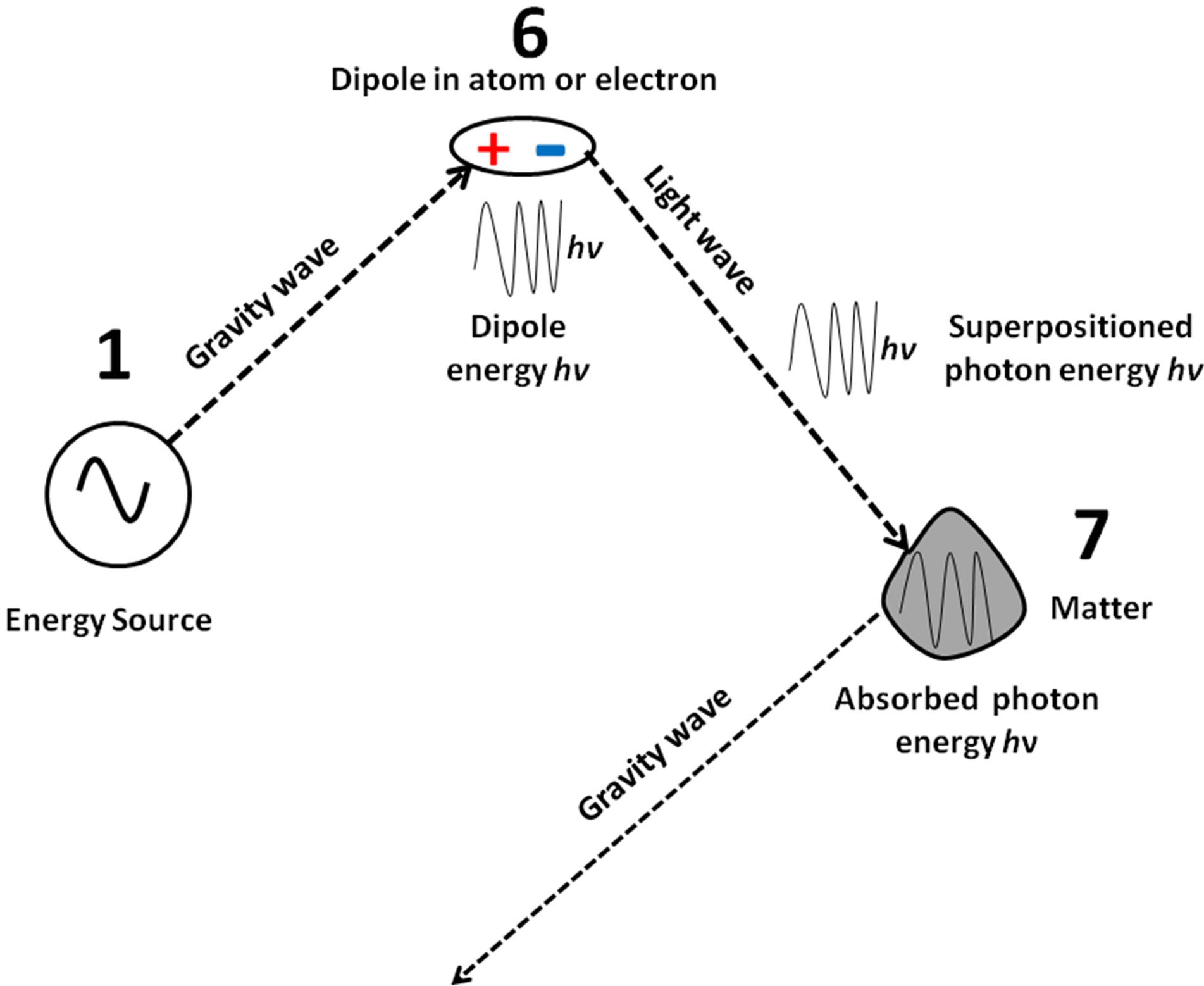
Figure 3. Electrons with high energy can be decelerated. The electron contains dipoles. The dipole 6 in an electron creates resonance with a gravity wave and the decelerated energy hν is superpositioned on the wave as a photon. This wave with frequency 69.9 Hz and v is re-emitted as e.g. light wave. The superpositioned energy hν can be absorbed in matter 7, whereby the light wave is converted into the original gravity wave with frequency 69.9 Hz.
From the Energy Source and the earth as described previously [14]. Each ED received gravity waves from e.g. the Energy Source and re-emitted these gravity waves to the other ED. The ED consisted of two copper disks, with diameter 20 mm, spaced by a thin (0.05 mm) plastic foil. One disk was connected to the positive pole of a voltage source U. The other disk was connected to the negative pole, Figure 4. This created an internal electric field Ei, e.g. 106 V/m at U = 50 V. Measurements were performed with the disks connected to a 9 V battery, forming a portable ED, detached from external influence (e.g. AC, ground).
Measurements in the present study of TEM wave field vector amplitudes E and B were made almost identically to those described previously [13,14]. Those reports describe in detail how the position and amplitudes of electric and magnetic field vectors were measured using a charge meter. The charge meter is described in detail previously [13]. In summary, the charge meter contained a probe with charge density ρ. The probe was moved, with constant speed, through the TEM wave’s electric field vectors E.
This resulted in an electric body force ρE on the probe’s charge density ρ. This current pulse was amplified and displayed. This probe was also moved, with constant speed, through the TEM wave’s magnetic field vectors B, which resulted in a magnetic body force J × B on current J in the probe. In this case B was field vectors, implying that div B was large and resulted in a distinct current pulse.
A permanent magnet with magnetic field Bm (1 µT) was inserted within the TEM wave’s path. This exerted a force on the TEM wave’s positive and negative field vectors. It resulted in that the positive field vectors E+ and B+ were diverted the distance d+ to one side and the negative field vectors E− and B− were diverted the distance d− to the opposite side [13,14]. Gravity waves
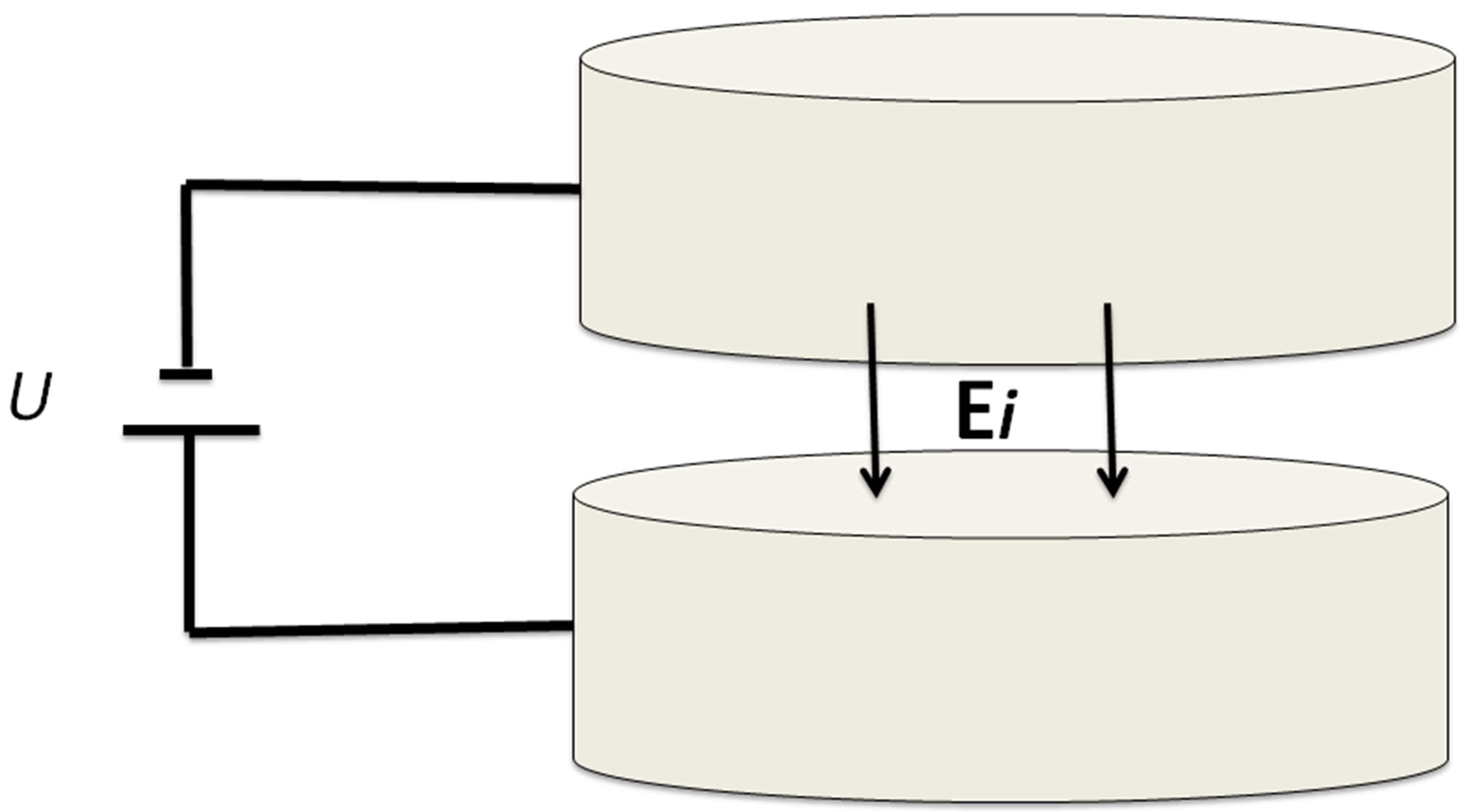
Figure 4. Two copper disks, with a diameter 20 mm, were spaced by a thin (0.05 mm) plastic foil. One disk was connected to the positive pole of a voltage source U, and the other disk to the negative pole. This created an internal electric field Ei. This device, called ED, received and reemitted gravity waves.
(TEM waves) propagating in one direction, from Source 1 to Source 2, were influenced so that their field vectors were diverted in e.g. the horizontal plane, see Figure 5. Gravity waves propagating in the opposite direction (e.g. from Source 2 to Source 1) were influenced so that their field vectors were diverted in the opposite plane, i.e. the vertical plane, see Figure 6. This enabled measurement of the two directions separately. The field vectors propagated in smooth bows distanced by the magnetic field Bm. This method facilitated separation of the TEM waves positive electric and magnetic field vectors as well as its negative electric and magnetic field vectors. It enabled measurement of TEM waves propagating in two directions separately.
Note that the above method is only possible to use on extremely low frequency, coherent and polarized field vectors, i.e. gravity waves and their field vectors [14].
Measurements were performed 50 km south of Stockholm, Sweden.
Analysis. The experiments were performed blindly, randomly and repeated 3 times.
4. Results
Experiments 1 to 4 aimed at verifying the theoretical model, presented in the Section 2. One ED was positioned at Source 1. Source 2 consisted of one ED which
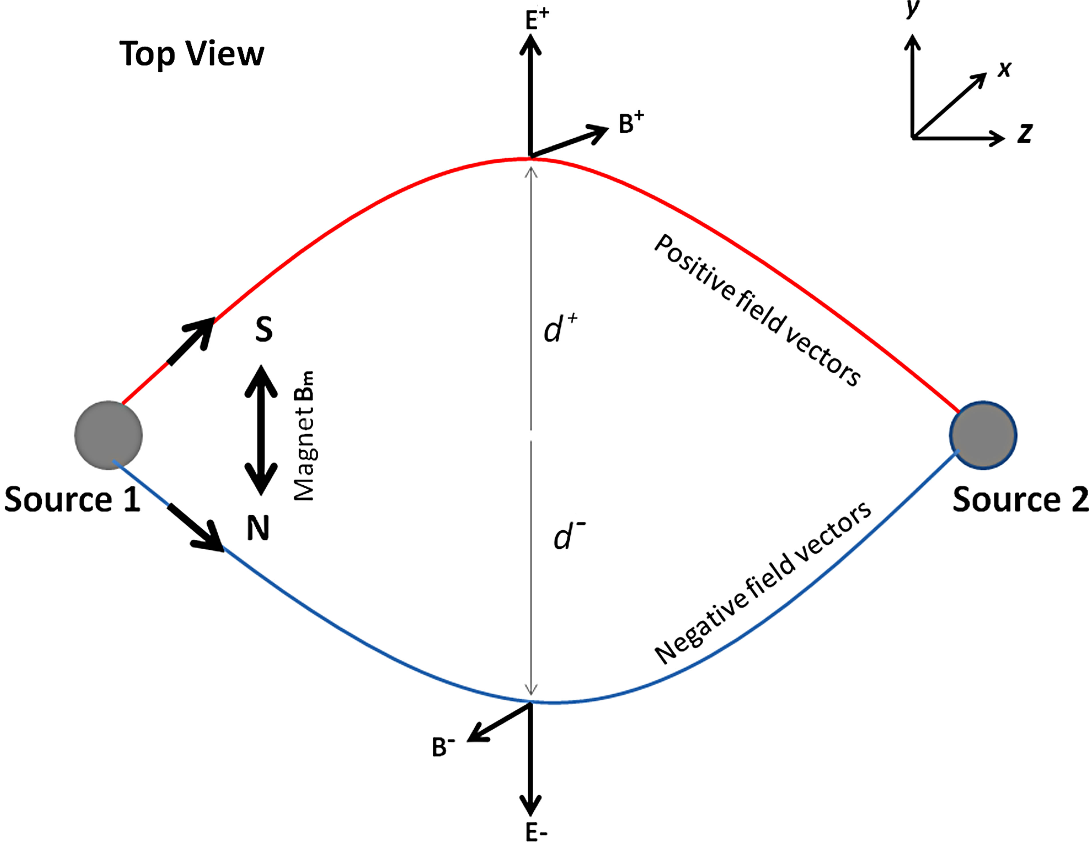
Figure 5. Measuring TEM waves propagating from Source 1. Two EDs, as described in Figure 4, Source 1 and Source 2, were positioned at 10 m distance, z-direction. Source 1 was connected to a 9 V battery and Source 2 was also connected to a 9 V battery. This resulted in that TEM waves (gravity waves) propagated between the two sources. A permanent magnet Bm was inserted (in the x-direction) within the TEM waves 5 m from Source 1. TEM waves propagating from Source 1 to Source 2 were diverted in the horizontal plane. This resulted in that positive field vectors were diverted the distance d+. The negative field vectors were diverted the distance d− to the opposite side. This enabled separation of the TEM waves positive and negative field vectors.
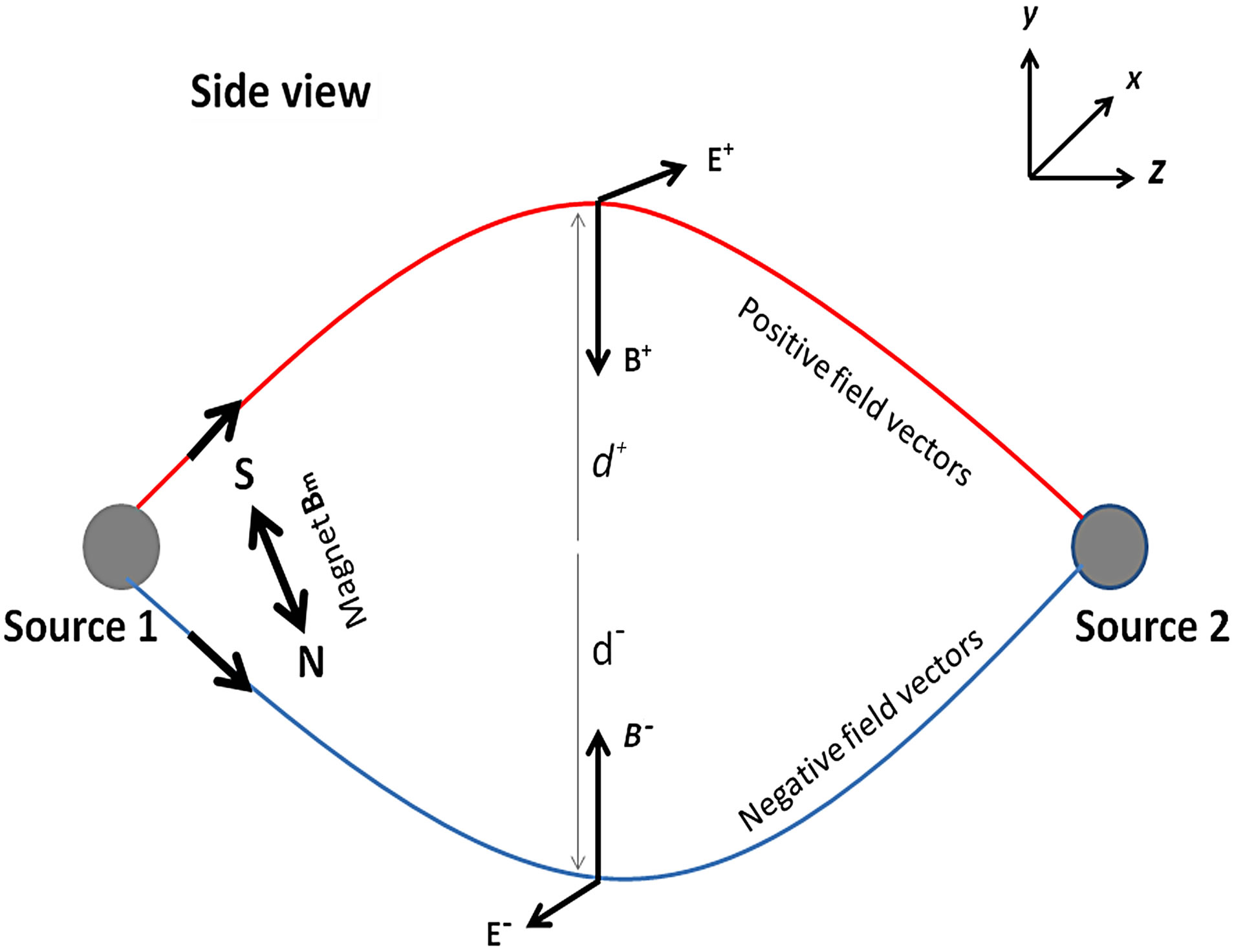
Figure 6. Measuring TEM waves propagating from Source 2. Two EDs, as described in Figure 4, Source 1 and Source 2, were positioned at 10 m distance, z-direction. Source 1 was connected to a 9 V battery and Source 2 was also connected to a 9 V battery. This resulted in that TEM waves (gravity waves) propagated between the two sources. A permanent magnet Bm was inserted (in the x-direction) within the TEM waves 5 m from Source 1. TEM waves propagating from Source 2 to Source 1 were diverted in the vertical plane. This resulted in that positive field vectors were diverted the distances d+. The negative field vectors were diverted the distance d− to the opposite side.
was located at the distance 10 m, and in the z-direction relative to Source 1. Each ED was connected to a 9 V battery. It produced gravity waves propagating in the z-direction from Source 1 to Source 2 and gravity waves propagating in the -z-direction from Source 2 to Source 1. It was also observed that Source 1 and Source 2 received and re-emitted gravity waves from and to the Energy Source and from and to the earth (i.e. ground). Hence, the gravity waves originated from these sources. Consequently, the EDs did not generate TEM waves; their only function was to create resonance with gravity waves originating from the Energy Source and earth and to reemit these gravity waves (unaltered) between the two EDs, Source 1 and Source 2. So far this experiment layout was similar to an experiment described previously [14].
Experiment 1. The purpose with this experiment was to verify if gravity waves, emitted from the electronic device ED, generated positive and negative electric and magnetic field vectors. The experiment comprised extremely low frequency gravity waves with frequency 69.9 Hz generated by the Energy Source. Measurements were performed 5 m in front of Source 1 (i.e. at the midpoint between Source 1 and Source 2). The charge meter was moved slowly through the x, y plane. This displayed presence of field vectors as shown in Figure 7. The positive magnetic field vector B+ was oriented in the y-direction

Figure 7. The TEM wave’s field vectors were oriented perpendicular (x, y plane) to the TEM wave’s motion (z-direction).
(influenced by the geomagnetic field), the positive electric field vector E+ was oriented in the x-direction, the negative magnetic field vector B− was oriented in the -y-direction and the negative electric field vector E− was oriented in the -x-direction. The measured field vector lengths were 2.6 m. The nature of each magnetic field vector was determined by inserting the magnet Bm close to the edge of the magnetic field vector, i.e. Bm directed in the x-direction and 2.6 m from the centre. B+ rotated away from the magnets positive pole and B− rotated away from the magnets negative pole. The nature of each electric field vector was determined by inserting a 1.5 V AAA battery on the x-axis close to the edge of the electric field vector, i.e. the battery pole directed in the y-direction and ±x = 2.6 m. E+ rotated away from the positive battery pole and E− rotated away from the negative battery pole.
Experiment 2. The purpose with this experiment was to display the energy in TEM waves, emitted from the electronic device ED. Experiment 1 was repeated; however, the magnet Bm was inserted in the TEM wave’s path 5 m in front of Source 1 (i.e. at the midpoint), and directed in the x-direction. TEM waves propagating from Source 1 to Source 2 were measured. The TEM wave’s field vectors were diverted as described in Section 3, Figure 5. The magnetic field diverted the positive field vectors the distance d+ = 0.9 m in the x-direction and the negative field vectors the distance d− = 0.9 m in -x-direction, the field vector length was 1.3 m, see Figure 8. TEM waves propagating from Source 2 to Source 1 were diverted in the vertical plane as described in Figure 6. These field vectors were diverted 0.9 m and field vector

Figure 8. The permanent magnet Bm and its field divided the TEM wave where field vectors E+ and B+ were diverted the distance d+ to one side and E− and B− were diverted the distance d− to the opposite side.
Lengths were 1.3 m. Hence, Experiment 1, Figure 7 displays the sum of field vectors from TEM waves propagating in opposite directions while Experiment 2, Figure 8 displays field vectors from TEM wave propagating in only one direction. Consequently, the field vector lengths have less amplitude (50%). Hence, separating the TEM waves field vectors by a distance of e.g. 0.9 m did not influence the generated field vectors. The distances d+ and d− were proportional to the TEM wave energy.
Experiment 3. The purpose with this experiment was to verify that electromagnetic energy was superpositioned on gravity waves. A 50 mm long wire (antenna) was attached to the output terminator of signal generator. The antenna was positioned within the gravity waves close to Source 1. The generator frequency ν was set to 100 kHz and the output voltage U was varied from 0 to 1 mV RMS in increments of 0.1 mV. The experiment was arranged as described in Experiment 1 (i.e. without the magnet Bm). Initially (U = 0 mV) the E+, E−, B+ and B− field vector lengths were 2.6 m (see Figure 7). Generator voltage U = 0.1 - 1 mV resulted in that field vector lengths increased. The increase in E+, E−, B+ and B− field vector lengths were linear to the generator voltage U within measurement accuracy. Subsequently, the generator voltage was fixed, U = 0.5 mV, and generator frequency ν was varied from 3 Hz to 300 kHz displaying no variation in E+, E−, B+ and B− field vector lengths. The conclusion is that it was possible to superposition low frequency electromagnetic energy with frequency 3 Hz to 300 kHz on gravity waves. The increase in field vector E+, E−, B+ and B− amplitudes were proportional to the generator output voltage U and independent of generator frequency ν.
Experiment 4. The purpose of this experiment was to measure the energy of superpositioned electromagnetic energy. Experiment 3 was repeated; however, this time the magnet Bm was inserted in the TEM wave’s path 5 m in front of Source 1 (i.e. at the midpoint), and directed in the x-direction. TEM waves propagating from Source 1 to Source 2 were measured. The distance d+ was measured. The generator voltage U was increased from 0 to 1 mV in increments of 0.1 mV. This resulted in that the distance d+ increased from 0.9 m to 1.7 m and the increase was linear to generator voltage U. Figure 9 displays the E+ field vector length as function of the generator voltage U. Subsequently the generator voltage U was set to 0.5 mV and the generator frequency ν was varied from 3 Hz to 300 kHz in increments of 50 kHz. This resulted in increase in distance d+ from 0.9 m to 2.1 m and where the increase was linear to generator frequency ν. Figure 10 displays the E+ field vector length as function of the generator frequency ν. The conclusion is that the energy in the new wave was the sum of energy contained in the gravity wave (69.9 Hz) and the superpositioned energy. The superpositioned energy was linear to the generator’s amplitude U and frequency v.
Experiment 5. The purpose with this experiment was to verify if an incandescent light bulb received gravity waves (69.9 Hz) from the Energy Source. In this experiment Source 2 consisted of an incandescent light bulb (Osram, 230 V, 60 W). Source 1 was the Energy Source. The light bulb was switched on and the experiment was allowed to stabilize during 15 minutes. It resulted in that gravity waves with frequency 69.9 Hz propagated from Source 1 (Energy Source) to Source 2 (in the z-direction). The magnetic field vectors B+ and B− were oriented in the vertical plane (y-direction). The length of all field vectors E+, E−, B+ and B− were 1.1 m.
Experiment 6. The purpose with this experiment was to verify if gravity waves, received by a light bulb, were influenced by the bulb power (watt, W) and the type of lamp. Experiment 5 was repeated using Philips halogen lamps GU 10 with power 25 W, 35 W and 50 W. The results were similar to Experiment 5. However, the E+, E−, B+ and B− field vector lengths were proportional to the bulb power W. The TEM wave amplitude is equal to TEM field vector length times a constant. Figure 11, graph marked “From Energy Source”, displays the measured relative amplitude of the positive electric field vector E+. The relative amplitude of the field vector for each lamp is displayed in % relative to the field vector length of the 50 W lamp (100%). Incandescent lamps (40, 60 and 75 W) and LEDs were also used, yielding similar results.
A candle was used, yielding similar results as a small power light bulb. The conclusion is that a halogen light bulb received gravity waves from the Energy Source and where the amplitude or energy of received gravity waves was linear to the light bulb power (W).
Experiment 7. The purpose with this experiment was to verify the characteristics of light TEM waves emitted
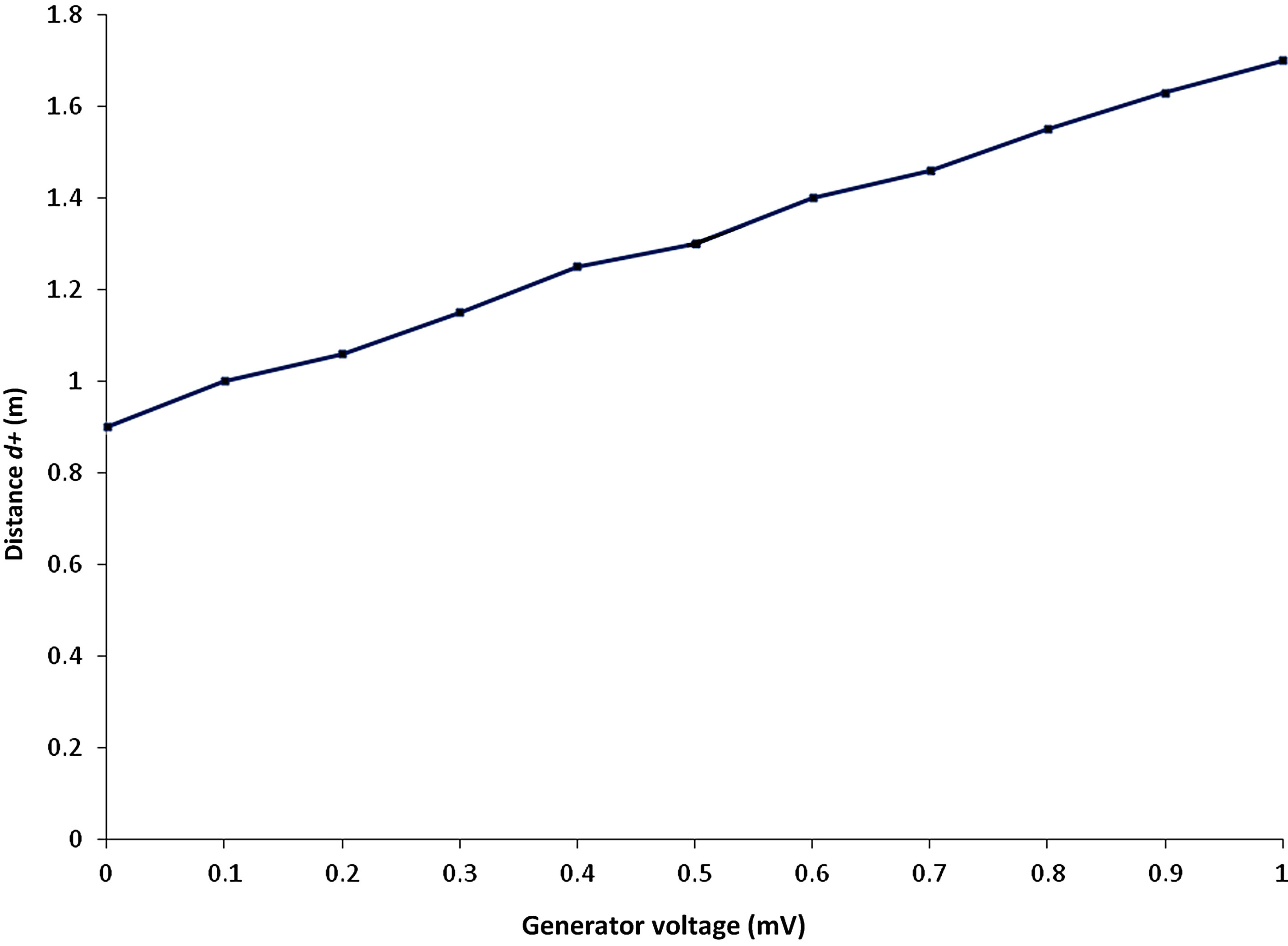
Figure 9. TEM wave energy measured as distance d+ as a function of generator voltage.
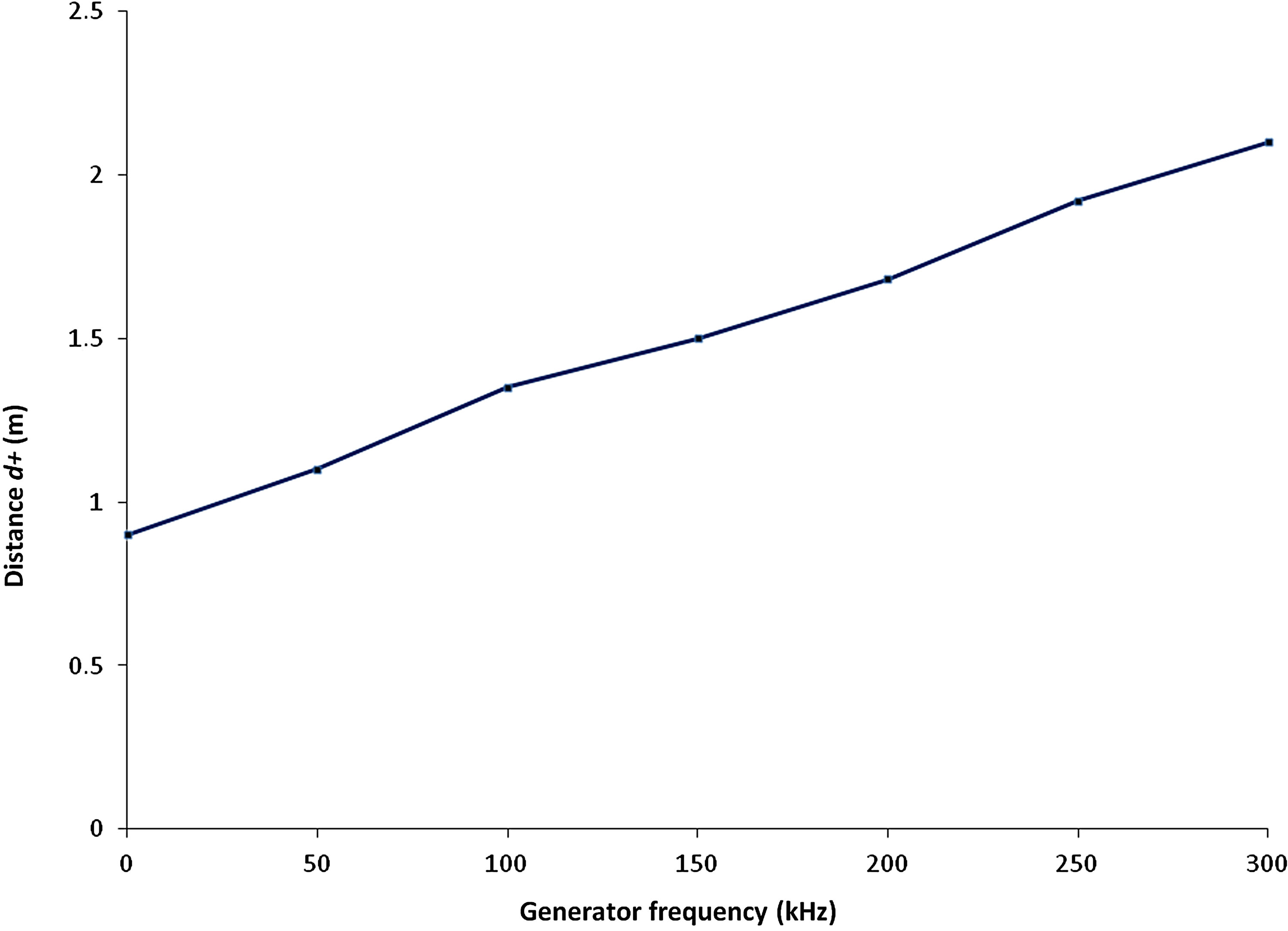
Figure 10. TEM wave energy measured as distance d+ as a function of generator frequency (kHz).
by a light source. In the following experiment Source 2 consisted of Philips halogen lamps GU 10 with power 25 W, 35 W and 50 W. The lamps contained an integrated reflector resulting in that the majority of light propagated within a narrow cone (25 W lamp beam angel was 25˚, 35 W and 50 W beam angels were 40˚). Source 1 was the Energy Source. The charge meter was moved slowly through the light beam, revealing the existence of low frequency (i.e. 69.9 Hz), polarized field vectors propagating along the light beam. The electric and magnetic field vector amplitudes (lengths) were measured, displaying equal length of E+, E−, B+ and B−. Figure 11, graph marked “From lamp”, displays the measured amplitude of the positive electric field vector E+. The am-
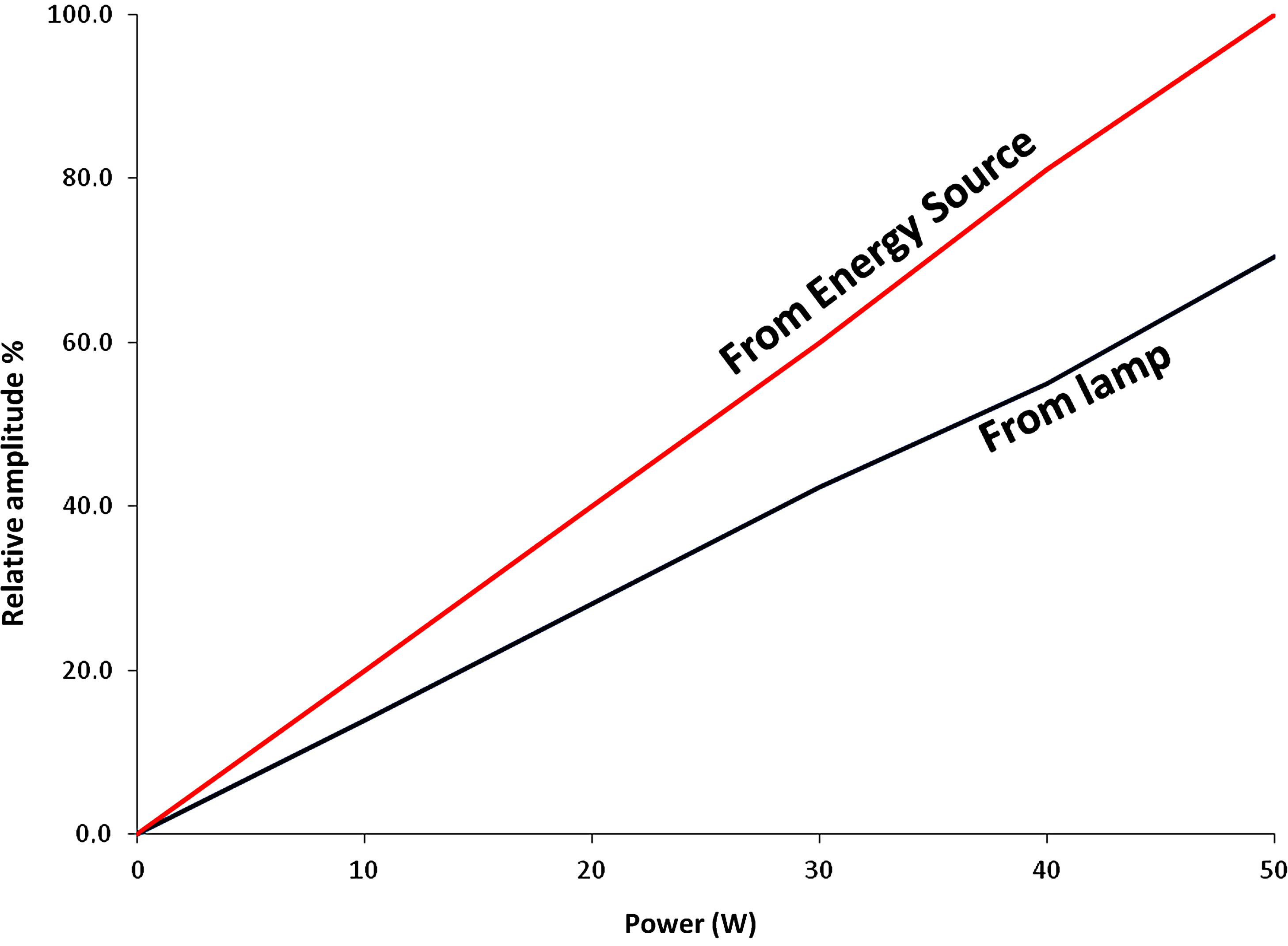
Figure 11. Field vector amplitude from received and emitted gravity waves. The low frequency (69.9 Hz) field vector amplitude E+, in gravity waves propagating from the Energy Source to the lamp, was measured as a function of lamp power (W) (graph marked “From Energy Source”). The low frequency (69.9 Hz) field vector amplitude E+, contained in light waves propagating from the lamp, was measured as a function of lamp power (W) (graph marked “From lamp”). The amplitude (length) of the field vector E+ for each lamp is displayed in % relative to the 50 W lamp (100%).
plitude of the E+ field vector for each lamp is displayed in % relative to field vector E+ of the 50 W lamp (100%) (see Experiment 6). It is proposed that the light energy, with frequency v, was superpositioned on gravity waves received from the Energy Source, creating light TEM waves. The low frequency energy (69.9 Hz) in the light TEM waves was proportional to the bulb power (W). The difference (30%) between received gravity waves and low frequency content in emitted light TEM waves was probably caused by internal loss in lamp reflector etc. Hence, there was good relationship between received gravity waves and emitted light TEM waves consisting of gravity waves with frequency 69.9 Hz and superpositioned light energy with frequency v.
Experiment 8. The purpose with this experiment was to verify that the light TEM wave consisted of a gravity wave with superpositioned light energy. Experiment 7 was repeated; however, the light beam was directed towards a wall (0.1 m concrete wall and also 0.15 m timber wall). Measurements were performed on the opposite side of the wall. It displayed that the low frequency (69.9 Hz) TEM wave and its field vectors travelled through the wall with no measurable loss or change of direction. The conclusion is that a light wave consisted of a gravity wave (69.9 Hz) and where the light energy v was superpositioned. When the light energy was removed (e.g. dissipated as heat in the wall), the light wave was converted back to the original gravity wave (69.9 Hz).
Experiment 9. The purpose with this experiment was to prove that light from the sun consisted of light energy superpositioned on gravity waves. A mirror (diameter 0.11 m) was directed towards the sun and twisted so that the reflected beam propagated approximately 300 degrees to the received beam. This beam was directed towards a wall. The reflected beam contained low frequency (i.e. 69.9 Hz), polarized field vectors propagating along the sun light beam, the field vector length was 2.3 m. Measurements were performed on the opposite side of the wall. It displayed that the low frequency (69.9 Hz) TEM wave and its field vectors travelled through the wall with no measurable loss or change of direction. The conclusion is that light from the sun consisted of a gravity wave where the light energy was superpositioned. When the sun light energy was removed (e.g. dissipated as heat in the wall), the light wave was converted back to the original gravity wave (69.9 Hz).
Experiment 10. The purpose with this experiment was to verify if radio transmitters received gravity waves from the Energy Source. Experiment 5 was repeated using a radio transmitter instead of light bulbs as Source 2. A SonyEricsson Experia (1.8 GHz) cellular phone (in activated mode) yielded results similar to Experiment 5; however, the received gravity wave (69.9 Hz) field vector lengths were smaller, i.e. 0.2 m. Communication radios (Lafayette 27 MHz and ICom 150 MHz) were also used in transmit mode, yielding similar results with received field vector length 0.4 m (ICom). It is proposed that radio waves consisted of gravity waves and where the energy in the radio antenna, with frequency v, was superpositioned on gravity waves.
Experiment 11. The purpose with this experiment was to demonstrate the general principles of universal energy transfer. Experiment 9 was repeated. However, the SonyEricsson Experia cellular phone (in active mode) was positioned behind the wall and 0.5 m from the reflected gravity wave originating from the sun and its light. The gravity wave bent smoothly to the cellular phone and was converted into a radio wave. It is proposed that gravity waves propagated from a singularity in the universe to the sun. Light energy was superpositioned on some gravity waves, whereby they were converted into light TEM waves. A fraction was radiated to the mirror and then reflected to the wall. The light energy with frequency v was absorbed, whereby the light TEM wave was converted back to the original gravity wave (69.9 Hz). The cellular phone energy attracted gravity waves, preferably waves propagating in its vicinity. The energy in the radio antenna was superpositioned on these gravity waves, resulting in that they were converted into radio frequency plane TEM waves. It is proposed that gravity waves were the universal carrier of energy, they were indestructible and can be used and reused to carry energy of any frequency.
Experiment 12. The purpose of this experiment was to investigate the influence of magnetic and electric fields on light TEM waves. Experiment 5 was repeated. The light beam was exposed to a magnetic field Bm and an electric field from a battery. The charge meter was moved carefully perpendicular to the light beam, i.e. in the x, y plane. The direction of the low frequency (69.9 Hz) field vectors was measured. It was impossible to change the direction of these field vectors or the light beam. The conclusion is that photon energy contained in the light TEM waves was hv, i.e. 3 × 10¹³ times higher than energy contained in the gravity waves. In order to influence the light TEM wave the imposed electric or magnetic fields must be correspondingly strong.
Note 1. All experiments were arranged so that the field vector lengths were in the order of 0.5 - 3 m and which simplified measurement. This was arranged by selecting parameters like ED voltage, distance between EDs, magnetic field Bm, generator voltage etc.
Note 2. The magnetic field vectors B+ and B− were always directed in the vertical plane because of influence from the geomagnetic field. Hence, gravity waves were always polarized, which simplified measurement. This is described in detail in [13,14].
Note 3. Measurement of gravity wave frequency (69.9 Hz) has been described [14] and is not repeated here.
Note 4. Gravity waves encompassed the frequencies 69.9 Hz and 91.9 Hz [14]. In order to simplify only the influence from 69.9 Hz is included in the study. In the correct description 69.9 Hz is replaced by 69.9 Hz and/or 91.9 Hz.
5. Discussion
Accelerated electrons in e.g. a radio antenna can theoretically result in plane TEM waves according to Equations (1) and (2). Hence, the state of the art model is theoretically correct. However, energy in the electron’s dipole is also superpositioned on existing plane TEM waves (gravity waves). The latter transfer function is more efficient than the former and therefore the majority of or all energy will be transferred as superpositioned energy on gravity waves.
Experiment 4 displays that a 5 mm long wire attached to a generator with frequency 3 Hz can produce plane TEM waves. This is impossible according to the state of the art model where the antenna must have a length in the order of the generated TEM wave’s wavelength λ (λ = 108 m at 3 Hz). It has been reported [13] that 24 h period currents in the magnetosphere result in plane TEM waves with period 24 h (λ = 2.6 × 10¹³ m). These TEM waves are impossible to generate according to the state of the art model. However, 24 hour period as well as 3 Hz can be superpositioned on existing TEM waves, i.e. gravity waves.
Extremely low frequency TEM waves (gravity waves) cannot be measured using state of the art methods. That implies that measuring e.g. light result in that hν is measured, but not the 69.9 Hz TEM wave. The energy in the 69.9 Hz TEM wave is 3 × 10¹³ times smaller than hv and may appear insignificant. Nevertheless, this apparently insignificant difference represents the difference between a correct model of the photon and the TEM wave compared to today’s inaccurate model.
6. Conclusions
The study shows that radio and light frequency EM energy is superpositioned on existing low frequency TEM waves (gravity waves). The gravity waves are generated by a singularity in the universe. The photon is a discrete package of EM energy superpositioned on a gravity wave.
The study displays large correlation between the theoretical model (Section 2) and results (Section 4). The theoretical model was verified at very low frequency 3 Hz, at high frequency 27 & 150 MHz, at UHF 1.8 GHz and at 5 × 10¹⁴ Hz (light). An earlier study [13] displays that the theoretical model is valid at 10−5 Hz (i.e. 24 h period). Hence, the theoretical model has been verified in the range 10−5 to 1014 Hz.
The study confirms that there is a duality between TEM wave and photon and which explains the wavephoton duality. The study also confirms that there is, in this case, a duality between electromagnetic theory and quantum physics. This implies that there is no need to explain photons by quantum physics because classical electromagnetic theory provides the accurate description.
The study shows that TEM waves (69.9 Hz), originating from a singularity in the universe, are carriers of EM energy in space. EM energy hv is superpositioned on these TEM waves, resulting in a TEM wave with frequency v + 69.9 Hz.
REFERENCES
- M. Alonso and E. J. Finn, “Fundamental University Physics Volume III: Quantum and Statistical Physics,” Addison-Wesley, Boston, 1968.
- V. V. Kobychev and S. B. Popov, “Constraints on the Photon Charge from Observations of Extragalactic Sources,” Astronomy Letters, Vol. 31, No. 3, 2005, pp. 147-151. doi:10.1134/1.1883345
- R. Lakes, “Experimental Limits on the Photon Mass and Cosmic Magnetic Vector Potential,” Physical Review Letters, Vol. 80, No. 9, 1998, pp. 1826-1829. doi:10.1103/PhysRevLett.80.1826
- E. Adelberger, G. Dvali and A. Gruzinov, “Photon-Mass Bound Destroyed by Vortices,” Physical Review Letters, Vol. 98, No. 1, 2007, Article ID: 010402. doi:10.1103/PhysRevLett.98.010402
- C. Burgess and G. Moore, “The Standard Model: A Primer,” Cambridge University Press, Cambridge, 2007.
- I. Bialynicki-Birula, “On the Wave Function of the Photon,” Acta Physica Polonica A, Vol. 86, No. 1-2, 1994, pp. 97-116.
- J. E. Sipe, “Photon Wave Functions,” Physical Review A, Vol. 52, No. 3, 1995, pp. 1875-1883. doi:10.1103/PhysRevA.52.1875
- M. Arndt, O. Nairz, J. Voss-Andreae, C. Keller, G. van der Zouw and A. Zeilinger, “Wave-Particle Duality of C60,” Nature, Vol. 401, No. 6754, 1999, pp. 680-682. doi:10.1038/44348
- S. S. Afshar, et al., “Paradox in Wave Particle Duality,” Foundations of Physics, Vol. 37, No. 2, 2007, pp. 295- 305. doi:10.1007/s10701-006-9102-8
- D. B. Melrose and R. C. McPhedran, “Electromagnetic Processes in Dispersive Media,” Cambridge University Press, Cambridge, 1991. doi:10.1017/CBO9780511600036
- B. I. Bleaney and B. Bleaney, “Electricity and Magnetism,” Oxford University Press, Oxford, 1965, pp. 256- 261.
- L. H. Ryder, “Quantum Field Theory,” 2nd Edition, Cambridge University Press, Cambridge, 1996. doi:10.1017/CBO9780511813900
- H. W. Giertz, “Extremely Low Frequency Electromagnetic Energy in the Air,” Journal of Atmospheric and Solar-Terrestrial Physics, Vol. 72, No. 9-10, 2010, pp. 767- 773. doi:10.1016/j.jastp.2010.03.022
- H. W. Giertz “Gravity Caused by TEM Waves Operating on Dipoles in Atoms,” International Journal of Astronomy and Astrophysics, Vol. 3, No. 2A, 2013, pp. 39-50.
- H. Wynberg, E. W. Meijer, J. C. Hummelen, H. P. J. M. Dekkers, P. H. Schippers and A. D. Carlson, “Circular Polarization Observed in Bioluminescence,” Nature, Vol. 286, No. 5773, 1980, pp. 641-642. doi:10.1038/286641a0
- J. C. Kemp and R. D. Wolstencroft, “Interstellar Circular Polarization: Data for Six Stars and the Wavelength Dependence,” Astrophysical Journal, Vol. 176, 1972, pp. L115-L118.