Journal of Encapsulation and Adsorption Sciences
Vol. 3 No. 1 (2013) , Article ID: 29451 , 11 pages DOI:10.4236/jeas.2013.31004
Nanorobot Drug Delivery System for Curcumin for Enhanced Bioavailability during Treatment of Alzheimer’s Disease
Advanced Technology, Lone Star College, Houston, USA
Email: Kal.Sharma@lonestar.edu
Received December 29, 2012; revised January 29, 2013; accepted February 7, 2013
Keywords: Nanorobot; Alzheimer’s Disease; Curcuma Longa; Photodynamic Therapy; Intrathecal Infusion; Denbigh Reaction Scheme
ABSTRACT
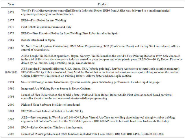
Robotics has emerged as a collegiate course about 20 years ago at Stanford University, Stanford, CA. From the first IRB6, the electrically powered robot in 1974, the industry has grown over a 30-year period. A leading supplier of robots has put out over 100,000 robots by year 2001. Robot capable of handling 500 kg load was introduced in 2001, IRB 7000. A number of advances have been made in nanostructuring. About 40 different nanostructuring methods were reviewed recently [1]. Nanobots can be developed that effect cures of disorders that are difficult to treat. Principles from photodynamic therapy, fullerene chemistry, nanostructuring, X-rays, computers, pharmacokinetics and robotics are applied in a design of nanorobot for treatment of Alzheimer’s disease. The curcuma longa that has shown curative effects in rats’ brain with Alzheimer’s is complexed with fullerenes. The drug is inactive when caged. It is infused intrathecally into the cerebrospinal system. Irradiation of the hypothalamous and other areas of the brain where Alzheimer’s disease is prevalent lead to breakage of fullerenes and availability of the drug with the diseased cells. Due to better mass transfer, better cure is affected. The other plausible reactions such as addition polymerization of fullerene, polycurcumin formation and other hydrolysis reactions are modeled along with the drug action under the Denbigh scheme of reactions. The fractional yield of drug-curcumin interaction is a function of intensity of radiation, frequency of radiation, patient demographics, age, gender, and other disorders etc. Chromophore in curcumin is used as a sensor and computer imaging and feedback control design can result in more bioavailability for curcumin therapeutic action to cure Alzheimer’s disease. This study examines the principles used in the design, the strategy of the design of the nanorobot drug delivery system with a specific target and pharamacokinetic formulation of the associated competing parallel reactions. The burrow and link capabilities at a nanoscopic level are also available if needed.
1. Introduction
About 4000 mistakes are made by surgeons every year [2]. There are regions such as the hypothalamus in the cranium that the surgeon cannot reach in the operating table on account of high morbidity rates for patients who underwent open brain surgery. A number of patients have cancer that is terminal. Knowledge of the presence of malign cells wherever it is in the human anatomy is not sufficient to affect cures. Nanorobot drug delivery systems can be a solution to these problems. Advances in the areas of robotics, nanostructuring, medicine, bioinformatics, computers can lead to the development of nanorobot drug delivery system. Nanorobots can offer a number of advantages over current methods such as; 1) use of nanorobot drug delivery systems with increased bioavailability; 2) targeted therapy such as only malignant cells treated; 3) fewer mistakes on account of computer control and automation; 4) reach remote areas in human anatomy not operatable at the surgeon’s operating table; 5) as drug molecules are carried by nanorobots and released where needed the advantages of large interfacial area during mass transfer can be realized; 6) non-invasive technique; 7) computer controlled operation with nobs to fine tune the amount, frequency, time of release; 8) better accuracy; 9) drug inactive in areas where therapy not needed minimizing undesired side effects. Fullerenes were mass produced by FCC, Frontier Carbon Corporation at 40 tons/year in 2003.
1.1. Development of Robotics as Colelgiate Course
Industrial robots came about in the 1960s. The adoption of robotic equipment came about in the 1980s. In the late 1980s, there was a pullback in the use of robots. Use of industrial robots has been found to be cheaper than manual labor. More sophisticated robots are emerging. Nanorobot drug delivery systems can be one such robot. 78% of the robots installed in the year 2000 were welding and material-handling robots. The Adept 6 manipulator had 6 rotational joints. The most important form of the industrial robot is the mechanical manipulator. The mechanics and control of the mechanical manipulator are described in detail in introductory robotics courses [1]. The programmability of the device is a salient consideration. The math needed to describe the spatial motions and other attributes of the manipulators is provided in the course. The tools needed for design and evaluation of algorithms to realize desired motions or force applications are provided by control theory. Design of sensors and interfaces for industrial robots is also an important task. Robotics is also concerned with the location of objects in 3 dimensional space such as its: 1) position and orientation; 2) coordinate system and frames of reference such as tool frame and base frames; 3) transformation from one coordinate system to another by rotations and translations.
Kinematics is the science of motion that treats motion without regard to the forces that cause it. In particular, attention is paid to velocity, acceleration and acceleration of the end effector. The geometrical and time based properties of the motion are studied. Manipulators consist of rigid links that are connected by joints that allow relative motion of neighboring links. Joints are instrumented with position sensors which allow the relative motion of neighboring links to be measured. In case of rotary or revolute joints, these developments are called joint offset. The number of independent position variables that would have to be specified in order to locate all parts of the mechanism is the number of degrees of freedom.
End effector is at the end of the chain of links that make up of the manipulator. This can be a gripper, a welding torch, an electromagnet, etc. Inverse kinematics is the calculation of all possible sets of joint angles that could be used to attain the given position and orientation of the end effector of the manipulator. For industrial robots, the inverse kinematic algorithm equations are nonlinear. Solution to these equations is not possible in closed form. The analysis of manipulators in motion in the workspace of a given manipulator includes the development of the Jacobean matrix of the manipulator. Mapping from velocities in joint space to velocities in Cartesian space is specified by the Jacobean. The nature of mapping changes with configuration. The mapping is not invertible at points called singularities.
Dynamics is the study of actuator torque functions of motion of manipulator. State space form of the NewtonEuler equations can be used. Simulation is used to reformulate the dynamic equations such that the acceleration is computed as a function of actuator torque. One way to effect manipulator motion from here to there in a specified smooth fashion is to cause each joint to move as specified by a smooth function of time. To ensure proper coordination, each and every joint starts and stops motion at the same time. The computation of these functions is the problem of trajectory generation. A spline is a smooth function that passes through a set or via points. End effector can be made to travel in a rectilinear manner. This is called Cartesian trajectory generation.
The issues that ought to be considered during the mechanical design of manipulator are cost, size, speed, load capability, number of joints, geometric arrangement, transmission systems, choice and location of actuators, internal position and sensors. The more joints a robot arm contains, the more dexterous and capable it will be. But it will also be harder to build and be more expensive. Specialized robots are developed to perform specified tasks and universal robots are capable of performing wide variety of tasks. 3 joints allow for the hand to reach any position in 3 dimensional spaces. Stepper motors or other actuators can be used to execute a desired trajectory directly. This is called the linear positional control. Kinetic energy of the manipulator links can be calculated using the Langrangian formulation. Both the linear kinetic energy and rotational kinetic energies can be tracked.
The evolution of robots can be studied from the market experience of one leading manufacturer of robots for example, ABB robotics, Zurich, Switzerland. This shall be used later to place in perspective the increased interest in use of nanorobots in the hospital for drug delivery. The different products from ABB Robotics during a 30 year period are given below in Table 1 [3].
1.2. Development of Nanotechnology
Submarine nanorobots are being developed for use in branchy therapy, spinal surgery, cancer therapy, etc. Nanoparticles have been developed for use in drug delivery systems and for cure in eye disorders and for use in early diagnosis. Research in nanomedicine is under way in development of diagnostics for rapid monitoring, targeted cancer therapies, localized drug delivery, and improved cell material interactions, scaffolds for tissue engineering and gene delivery systems. Novel therapeutic formulations have been developed using PLGA based nanoparticles. Nanorobots can be used in targeted therapy and in repair work of DNA. Drexler and Smalley debated whether “molecular assemblers” that are devices capable of positioning atoms and molecules for precisely
Table 1. State of art in robots over a 40 year period.
defined reactions in any environment is possible or not. Feynman’s vision of miniaturization is being realized. Smalley sought agreement that precision picking and placing of individual atoms through the use of “Smalleyfingers” is an impossibility. Fullerenes, C60, are the third allotropic form of carbon. Soccer ball structured, C60, with a surface filled with hexagons and pentagons satisfy the Euler’s law. Fullerenes can be prepared by different methods such as: 1) first and second generation combustion synthesis; 2) chemical route by synthesis of corannulene from naphthalene. Rings are fused and the sheet that is formed is rolled into hemisphere and stitched together; 3) electric arc method. Different nanostructuring methods are discussed in [4,5]. These include: 1) sputtering of molecular ions; 2) gas evaporation; 3) process to make ultrafine magnetic magnetic powder; 4) triangulation and formation of nanoprisms by light irradiation; 5) nanorod production using condensed phase synthesis method; subtractive methods such as; 6) lithography; 7) etching; 8) galvanic fabrication; 9) lift-off process for IC circuit fabrication; 10) nanotips and nanorods formation by CMOS process; 11) patterning Iridium Oxide nanostructures; 12) dip pen lithography; 13) SAM, self-assembled monolayers; 14) hot embossing; 15) nanoimprint lithography; 16) electron beam lithography; 17) dry etching; 18) reactive ion etching; 19) quantum dots and thin films generation by; 20) sol gel; 21) solid state precipitation; 22) molecular beam epitaxy; 23) chemical vapor deposition; 24) CVD; 25) lithography; 26) nucleation and growth; 27) thin film formation from surface instabilities; 28) thin film formation by spin coating; 29) cryogenic milling for preparation of 100 - 300 nm sized titanium; 30) atomic lithography methods to generated structures less than 50 nm; 31) electrode position method to prepare nanocomposite; 32) plasma compaction methods; 33) direct write lithography; 34) nanofluids by dispersion. Thermodynamic miscibility of nanocomposites can be calculated from the free energy of mixing. The four thermodynamically stable forms of Carbon are diamond, graphite, C60, Buckminster Fullerene and Carbon Nanotube. 5 different methods of preparation of CNTs, carbon nanotubes were discussed. Thermodynamically stable dispersion of nanoparticles into a polymeric liquid is enhanced for systems where the radius of gyration of the linear polymer is greater than the radius of the nanoparticle. Tiny magnetically-driven spinning screws were developed. Molecular machines are molecules that can with an appropriate stimulus be temporarily lifted out of equilibrium and can return to equilibrium in the observable macroscopic properties of the system. Molecular shuttle, molecular switches, molecular muscle, molecular rotors, molecular nanovalves are discussed. Supramolecular materials offers alternative to top-down miniaturization and bottom-up fabrication. Self-organization principles hold the key. Gene expression studies can be carried out in biochips. CNRs are a new generation of self-organizing collectives of intelligent nanorobots. This new technology includes procedures for interactions between objects with their environment resulting in solutions of critical problems at the nanoscopic level. Biomimetic materials are designed to mimic a natural biological material. Characterization methods of nanostructures include SAXS, small angle X-ray scattering, TEM, transmission electron microscopy, SEM, scanning electron microscopy, SPM, scanning probe microscope, Raman microscope, AFM atomic force miscroscopy, HeIM helium ion microscopy.
1.3. Recent Developments in Nanorobots
Some investigators refer to nanorobotics as molecular robotics. A variety of definitions for nanorobots are available in the literature. Per Ummat et al. [7] nanorobots refer to any active structure with capability for actuation, sensing, signaling, information processing, intelligence or swarm behavior at the nanoscale. Sandia National Laboratories [8] provided a classification of nanorobotics into two main areas: 1) Design, simulation, control and coordination of robots with nanoscale dimensions. Naorobot drug delivery systems will fall into this category/Much of the research conducted in this area remains theoretical currently. This is primarily because of the difficulties in manufacturing these devices. Synthetic nanorobot development is driven by emulation of biological nanorobotic systems that exist in nature (Requicha [9]). Lot of bionanorobots is protein based. 2) Manipulation/assembly of nanoscale components with microscale instruments of or robots/nanomanipulators. A number of research papers have appeared in the literature in this area. As can be seen from section 1.2 advances in nanostructuring methods have been made. Practical technologies for the manipulation and assembly of nanoscale structures into functional nanodevices need be developed. Nanomanipulation and nanoassembly may be critical in the development of synthetic nanorobots.
1.4. Alzheimer’s Disease and Drugs Used Today
By the year 2050 the number of patients with Alzheimer’s disease will be 16 million. The cost of memory loss is about $1.1 trillion. Currently 5 million patients suffer from Alzheimer’s in this country, United States. The root curcuma longa, turmeric root has found to have a positive effect in experiments with rats [9]. The drugs used such as bapinezumab from Eli Lily and solanezumab from Johnson and Johnson used today are used to target the amyloid-β protein in the brain. This protein has been found to misfold and results in clump formation in patients’ brains. Furthermore these drugs are expensive. Turmeric root is used in curries in India and is readily available from farms at a lower cost. It is yellow colored. This is recommended by Ayurveda and Siddha Medicine. It is known to possess anti-inflammatory and antioxidant properties.
Curcumin (Figure 1) has been found to decrease inflammation in the brain. It causes reduction in oxyradicals formed in patients’ brain,
1.5. Nanomedicine-Advantages of Nanorobot Drug Delivery System
Nanorobots can offer a number of advantages over current methods such as: 1) use of nanorobot drug delivery systems with increased bioavailability; 2) targeted therapy such as only malignant cells treated; 3) fewer mistakes on account of computer control and automation; 4) reach remote areas in human anatomy not operatable at the surgeon’s operating table; 5) as drug molecules are carried by nanorobots and released where needed the advantages of large interfacial area during mass transfer can be realized; 6) non-invasive technique; 7) computer controlled operation with nobs to fine tune the amount, frequency, time of release; 8) better accuracy; 9) drug inactive in areas where therapy not needed minimizing undesired side effects; 10) greater speed of drug action. Frietas [10] defined nanomedicine as follows:
“Nanomedicine is the preservation and improvement of human health using molecular tools and molecular knowledge of the human body.”
Tiny magnetically-driven spinning screws were developed by Ishiyama et al. [11]. These devices were intended to swim along veins and carry drugs to infected tissues or even to burrow into tumors and kill them with supply of heat. Untethered microrobot containing ferromagnetic particles under forces generated by MRI magnetic fields were tested for travel through the human
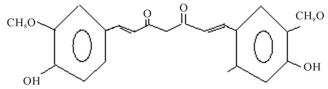
Figure 1. Structure of curcumin.
anatomy at the Nano Robotic laboratory at Montreal, Canada in 2003.
A nanorobot to measure surface properties was patented [12]. This technology is 10 - 20 years in the future. The nanorobot unit has a manipulation unit and an end effector. The end effector can be a senor or made to move as close as possible to the surface of interest. The drive device has piezoelectric drives. The resolution of the measurement can be in the nanometer range and the actual measurement in the centimeter range. The nanorobot is made sensitive in all directions, in multiple dimensions. It can operate under vacuum. Surface roughness can be measured using nanorobots.
A patent was developed [13] for minimally invasive procedure by means of DPR, Dynamic Physical Rendering. Use of “intelligent”, “autonomous” particles were made. An interventional aid is formed with the aid of self-organizing nanorobots. These nanorobots were made of catoms. C-arm angiography are used to monitor DPR procedures. A 3 dimensional image data record on target region is obtained. The determined form was converted to a readable and executable program code for the catoms of the nanorobots. The determined form was transferred to a storage unit. The program code was executed in order to achieve self-organization in the unstructured catoms that were introduced in the target region. The execution of the program was triggered by a timer or position sensor. The intervention aid is used as an endovascular target region.
Nanocrystal with motor properties was patented [14]. Reciprocating motor is formed by a substrate, atom reservoir, nanoparticle ram and nanolever. The nanoparticle ram is contacted by the nanolever resulting in movement of atoms between the reservoir and the ram. Substrate and nanolever are made of MWNTs, multi-walled nanotubes made of Iridium. The substrate used was a silicon chip.
Nanoscale oscillator [15] was patented by Sea Gate technology, Scots Valley, CA. A microwave output is generated by application of a DC current that is allowed to pass through layers of magnetic structure separated by nanometer dimensions. Spin Momentum Transfer, SMT is a phenomena realized to exist in 1989. It can be used in MRAM devices. Phase-locked microwave spin transfer is the next advance of the technology. The electric current produced is in the GHz spectrum. The local magnetic field source is used in the application of a magnetic field to a free layer of spin momentum transfer stack. The magnetic source can be from a horseshoe magnet with poles stationed above and below the SMT stack. The magnetic source can take on other forms such as helical coil that surrounds the SMT or pancake type coils above and below the SMT stack or an annular pole and a coil that surround the stack. A permanent magnet may be planted above the stack. SMT stack consists of a top electrode, a free layer, a non-magnetic layer a pinned magnetic structure and a bottom electrode.
Nanowhiskers can be grown by control of nucleation conditions [16]. Nanowhisker formation on substrates can be made using the VLS, vapor-liquid-solid mechanism. A particle of catalyst material is placed on a substrate is heated in the presence of gases until it melts. A pillar is allowed to form under the melt. As the melt rises up on top of the pillar and a nanowhisker is formed. Miller direction (111) may be a preferred growth direction of the whiskers. The catalytic property is present at the interface of whisker and air. InP nanowhiskers, for example, were grown using metal-organic vapor phase epitaxy. Characterization of nanowhiskers is by electron microscopy. MOVPF is low pressure metal-orgaic vapor phase epitaxy process. 50 nm aerosol gold particles were deposited on InP substrate. This was placed on a horizontal reactor cell heated by radio frequency heated graphite suceptor. Hydrogen was used as carrier gas. Temperatuer was ramped tp 420˚C for 5 min. The molar fraction of flow rate in the cell was 0.015. Nanowhisker growth was found to commence upon addition of TMI, trimethylindium. The molar fraction of TMI was 3 millionth. Typical growth time for production of nanowhiskers was found to be 8 minutes.
2. Design and Control Strategy
The strategy for design of nanorobot drug delivery system among other things comprise of the following salient features:
1) Use fullerenes as carriers of curcumin.
2) Complex the fullerene with curcumin and deactivate the drug action as in other cases of photodynamic therapy.
3) Computer controlled irradiation can activate the fullerene. Breakage of fullerene is expected and release of curcumin at constant rate [17,18]. The intensity, wavelength and areas of brain where is irradiated is controlled using computer software.
4) Curcumin acts on the diseased cells and cure is affected.
5) Pharmacokinetic model with 4th order process for irradiation and competing parallel reactions for fullerene breakage, polymerization of fullerene and drug action is developed.
6) Time for drug release can be computed from the drug delivery model. Drug delivery model for fullerene nanorobot curcumin delivery system can be developed including all the main features of the procedure.
7) Chromophores in curcumin is used as a dye and picked up from imaging. Information from the sensor on drug action is compared against model and feedback control affected by changing the intensity and wavelength of irradiation. This is used to trigger feedback control or model based control of irradiation using computers.
8) Itrathecal route of entry for nanorobot fullerene curcumin complex can be preferred to sublingual entry. The choice of cerebrospinal fluid system may obviate any digestive disorders from fullerene carbon.
Conventional treatments lack in their selectivity. Drugs administered generally become active in areas where treatment is not needed. Sometimes negative side effects of the drugs can be prevalent in those areas. Suppression of side effects is emerging as a salient consideration in the development of new drugs and drug strategies. Nanorobot drug delivery systems that are act only in targeted areas can be more beneficial.
Complexing curcumin with fullerene may be more advantageous compared with binding with a polymer molecule as carrier. The dimensions of the macromolecule carrier are large. On account of its size it cannot migrate to any part of the human anatomy. In such cases the drug stays near the region it is administered during the duration of treatment. This may call for separate administration of complex to each area requiring treatment. This can consume lot more time and the procedure becomes impractical given a great number of treatment sites. The fullerene molecules as carriers can migrate to any region of the human anatomy such as the hypothalamus in the brain and be a better choice for carrier.
Attempts to design drug delivery system with liposome encapsulated drug involve the rupture of the membrane and drug release. This is triggered by irradiation and pH changes. The response was found to be inconsistent. The pathway to drug release is indirect. i.e., the irradiation and pH changes affect a photosensitizer. A compound in turn is generated that is capable of cleaving a specific entity in the liposome membrane. At temperatures below the body temperature of 37˚C the drug release drops. Thus at 15˚C the release rate was less than 15%. This limits the application of this design.
3. Pharmacokinetics of Curcumin Therapy
The irradiation is supplied to activate the fullerene and effect detachment of the cur cumin from the fullerene setting the onset of therapeutic action. The irradiation can also trigger polymerization of fullerene. Formation of polyfullerene can soak up the energy from irradiation that is needed for activation of the drug. Curcumin may polymerize to form polycurcumin. The selectivity of the breakage of fullerene cages and release of drug over formation of polyfullerene and formation of polycurcumin are studied using transient dynamic analysis of PFR, plug flow reactor and pharmacokinetics of Denbigh reaction. The therapeutic action of curcumin during Alzherimer’s disease can be viewed as a set of micro reactors. PFR analysis will be a more reasonable approximation of these processes. Denbigh scheme is the general scheme under which the parallel reactions of fullerene breakage, polymerization of fullerene and polymerization of cucrumin may fall under.
3.1. Transient Dynamics of Plug Flow Reactor, PFR
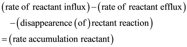
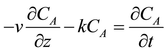
The composition of the fluid in a PFR, plug flow reactor, varies from point to point along a flow path. The mass balance on the reacting species need be made over a differential volume ADz as shown in Figure 2. A is the cross-sectional area of the PFR and Dz is the incremental length of the slice considered in Figure 2. This is different from a CSTR where the mass balance on the reacting species is performed over the volume of the CSTR. For a reacting species A with a inlet composition of CAi (mol∙m−3) and v is the superficial velocity of the fluid (m∙s−1) the mass balance over the slice 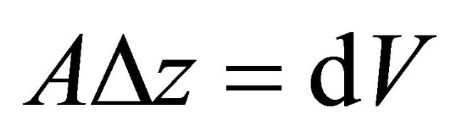 can be written as follows:
 (1)
(1)
 (2)
(2)
Dividing Equation (2) throughout by ADz and obtaining the limit as  Equation (2) becomes:
 (3)
(3)
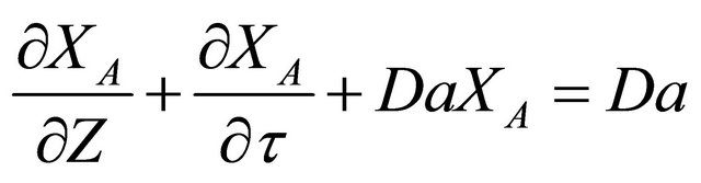
Equation (3) can be made dimensionless as follows:
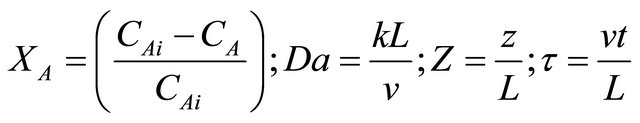 (4)
(4)
Upon substitution of Equation (5) in Equation (6):
 (5)
(5)
Differentiating Equation (5) with respect to dimensionless time:
 (6)
(6)
Differentiating Equation (3) with respect to dimen-
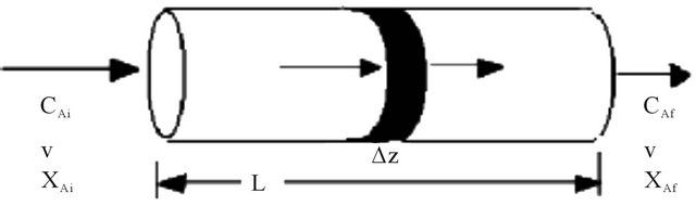
Figure 2. Transient dynamics in a plug flow reactor, PFR.
sionless distance:
 (7)
(7)
Conversion XA can be assumed to be analytic in the space and time . The order of the differentialion does not matter. i.e.,
 (8)
(8)
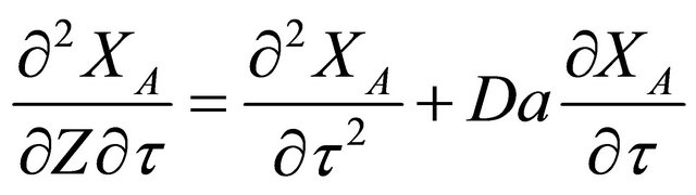
Adding Equations (6) and (7) and realization of Equation (8) leads to:
 (9)
(9)
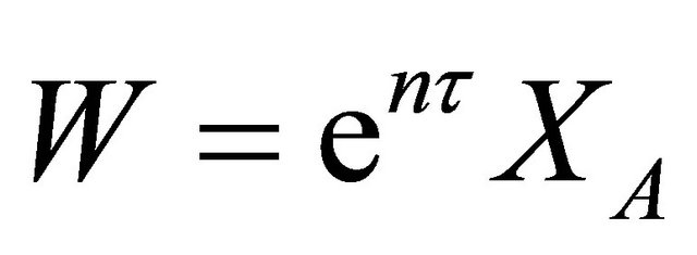
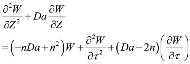
Equation (9) is a hyperbolic PDE, partial differential equation that is second order with respect to space and second order with respect to time. The exact form analytical solution to Equation (9) can be obtained as follows. Equation (9) is multiplied by ent. Equation (9) becomes:
 (10)
(10)
The term  can be seen to group and can be called as the wave concentration [19] such that:
 (11)
(11)
Now,
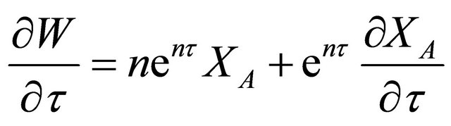 (12)
(12)
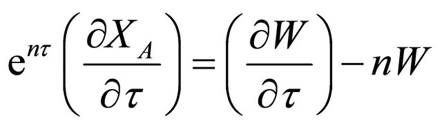 (12a)
(12a)
Differentiating Equation (12) again with respect to time, t
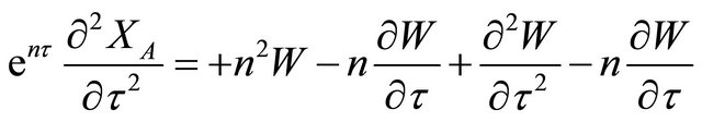
 (13)
(13)
Plugging Equaiton (13), Equaiton (12) and Equaiton (11) in Equaiton (10)
 (14)
(14)
For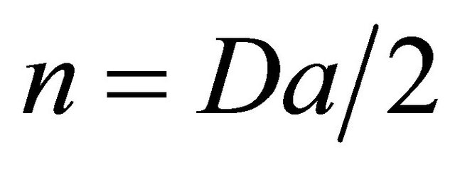 , Equaiton (14) becomes:
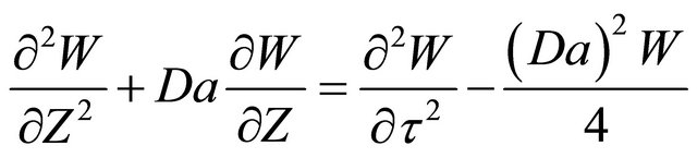 (15)
(15)
The steady state conversion can be obtained from Equaiton (15) as follows:
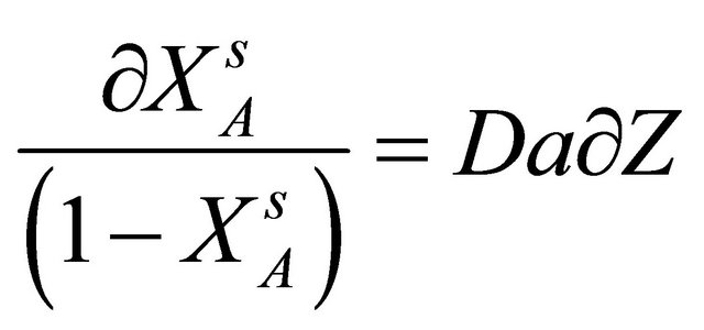 (16)
(16)
Integration of both sides of Equaiton (16) yields:
 (17)
(17)
At  So,
So,  Equation (17) becomes:
 (18)
(18)
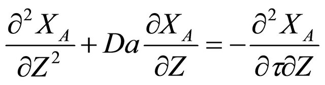
It can be seen that at steady state the conversion varies as a . Equaiton (15) can be multiplied throughout by emZ. The term
  can be seen to group and can be called as w:
 (19)
(19)
Now,
 (20)
(20)
 (21)
(21)
Substituting Equaiton (19)-(21) in Equaiton (15), Equaiton (15) becomes:
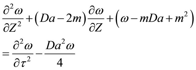 (22)
(22)
For , Equaiton (15) becomes:
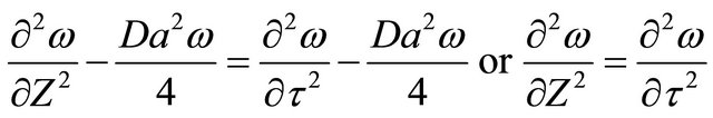 (23)
(23)
Equaiton (23) is the wave equation. In the dimensional form of independent variables:
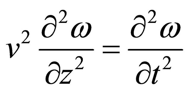 (24)
(24)
It can be seen that the solution to Equaiton (24) can be written as (Bird, Stewart and Lightfoot [20]):
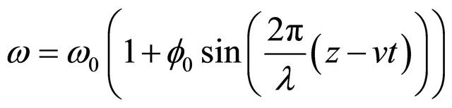 (25)
(25)
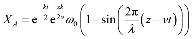
where l is the wavelength of a harmonic wave with amplitude  traveling in the z direction at a speed v. The solution for the transient conversion can be written as follows:
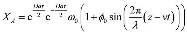 (26)
(26)
The Dankwert’s boundary condition at z = L can be applied as:
 (27)
(27)
 (28)
(28)
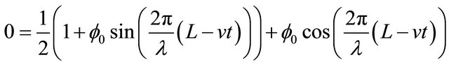
At the wave front, L = vt, Equaiton (28) becomes:
 (29)
(29)
 (30)
(30)
At the entrance of the reactor, the initial reaction rate is given by:
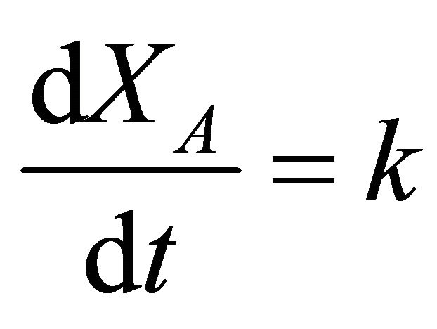 (31)
(31)
Differentiating Equaiton (30) with respect to t,
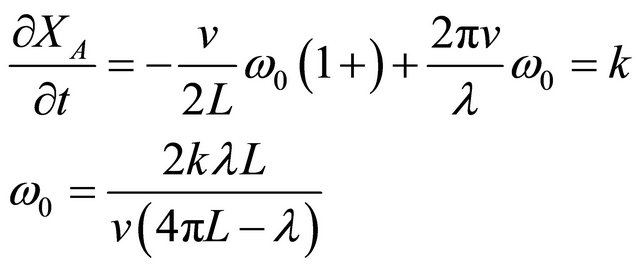 (32)
(32)
 (33)
(33)
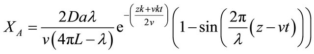
The transient conversion of drug-target interaction in a PFR is plotted in Figure 3 for a set of Damkhohler number and other parameters such as space time, length of the reactor, fluid velocity, reaction rate constant, wavelength of propagating wave.
3.2. Pharmacokinetics of Curcumin Drug and Polymerization Parallel Reactions
Denbeigh Scheme of Reactions
Consider the Denbigh scheme of reactions [21] performed in the CSTR shown in Figure 4. A scheme of reactions as shown in Figure 4 was discussed in [17] as a special case of Denbigh reactions. A state space model is developed in order to describe the dynamics of the 5 species, CA, CR, CT, CB and CS. The assumptions are that the inlet stream contains species A and B at a concentration of CAi and CBi and the initial concentrations of the other species are zero. The kinetics of the simple irreversible reactions shown in Figure 4 can be written as follows:
 (34)
(34)
 (35)
(35)
 (36)
(36)
 (37)
(37)
 (38)
(38)
The reactions are considered to perform in the CSTR similar to the one shown in Figure 5. Component mass
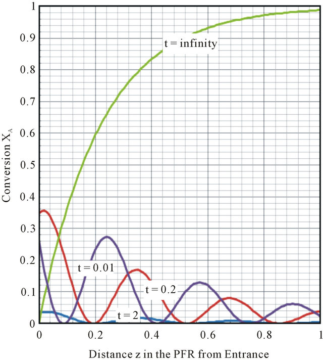
Figure 3. Conversion XA in PFR for Damkohler Number, Da = 6.75, v = 0.55 m∙s−1, L = 1.5 m; q = 2.7 hr, k = 2.5 hr−1, l = 0.33 m.
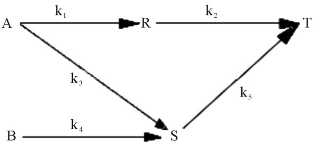
Figure 4. Denbigh scheme of reactions.
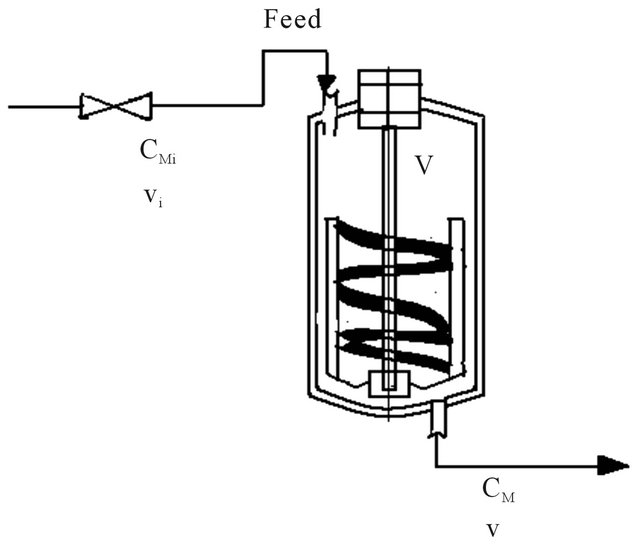
Figure 5. CSTR, Continuous stirred tank reactor.
balances on each of the species assuming incompressible flow and constant volume reactor can be written as follows:
Species A
 (39)
(39)
where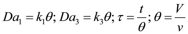 , q with units of (hr) is the residence time of the species in the reactor, V is the volume of the reactor, (liter) and v is the volumetric flow rate (lit∙hr−1) in and out of the reactor.
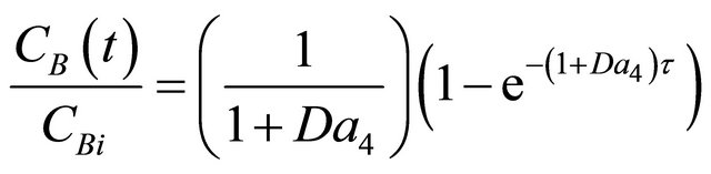
Species B
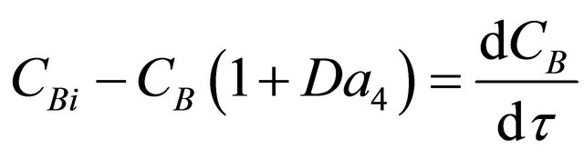 (40)
(40)
where 
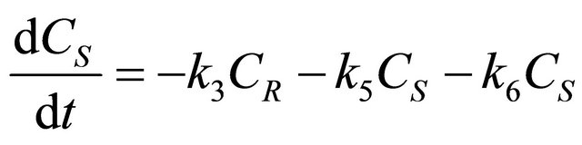
Species S
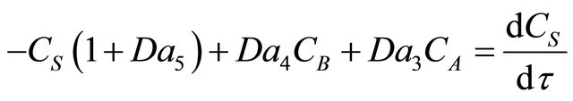 (41)
(41)
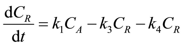
Species R
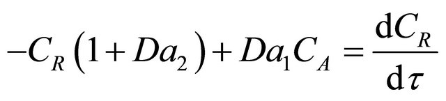 (42)
(42)
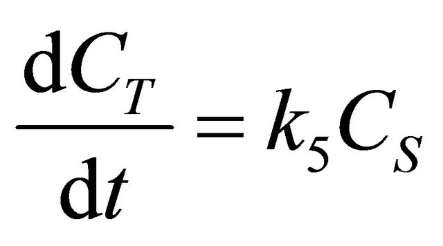
Species T
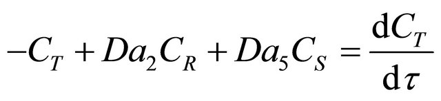 (43)
(43)
The model equations that can be used to describe the dynamics of the 5 reactant/product species in a CSTR can be written in the state space form as follows:
 (44)
(44)
The stability of the dynamics of the 5 reactants/products in the Denbigh scheme performed a CSTR can be studied by obtaining the eigenvalues of the rate matrix. The characteristic equation for the eigenvalues is obtained by evaluation of the following determinant:
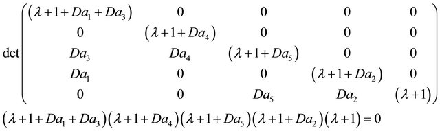 (45)
(45)
The 5 eigenvalues are negative when Damkohler numbers are greater than zero. When eigenvalues are all negative the system is considered to be stable.
The Laplace transform of the model equations developed in order to describe the transient dynamics (Equations (39)-(43)) for the 5 species in the Denbigh scheme in a CSTR can be written as follows:
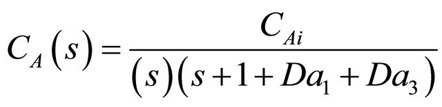 (46)
(46)
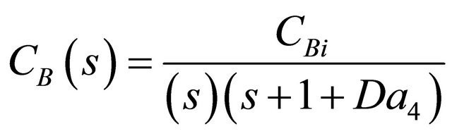 (47)
(47)
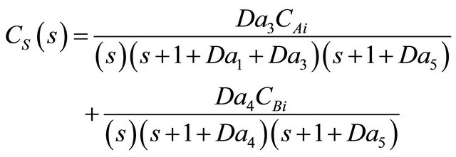 (48)
(48)
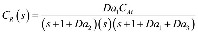 (49)
(49)
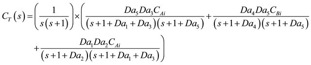 (50)
(50)
The inverse Laplace transform of Equaiton (46) can be obtained by invocation of the convolution theorem and written as:
 (51)
(51)
The inverse Laplace transform of Equaiton (47) can be seen from the time shift property to be:
 (52)
(52)
The inverse Laplace transform of Equaiton (48) can be obtained by look-up of Laplace inversion Tables in Mickley, Sherwood and Reed [22].
 (53)
(53)
3.3. State Space Representation
State space models are those that describe more than one variable at a given instant in time. Vector form for several variables is used. A set of n differential equations is represented by one equation in matrices and vectors. The coefficient matrix and input and output vectors are used. Output vector can be solved for by matrix manipulations. This would form the output response of the system. The stability of the system can be studied by looking at the Eigen values of the coefficient of the matrix. The different instabilities that may arise and the conditions under which they would arise are given in Table 2 [23].
3.3.1. Kinetics of Simultaneous Reactions in State Space Form
As an example a state space model is developed to describe the kinetics of the following set of reactions in series and in parallel as suggested in Levenspiel [18].
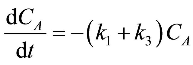
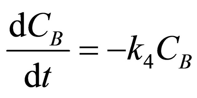
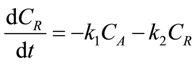
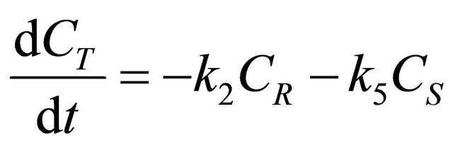
The kinetics of the 7 simultaneous reactions shown in Figure 6 is given below as follows:
 (54)
(54)
 (55)
(55)
 (56)
(56)
 (57)
(57)
 (58)
(58)
 (59)
(59)
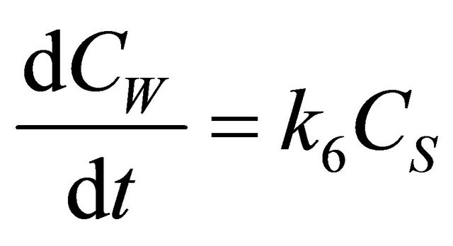 (60)
(60)
The above equations can be represented in the state space form in one line as follows:
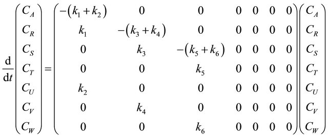 (61)
(61)
Or,
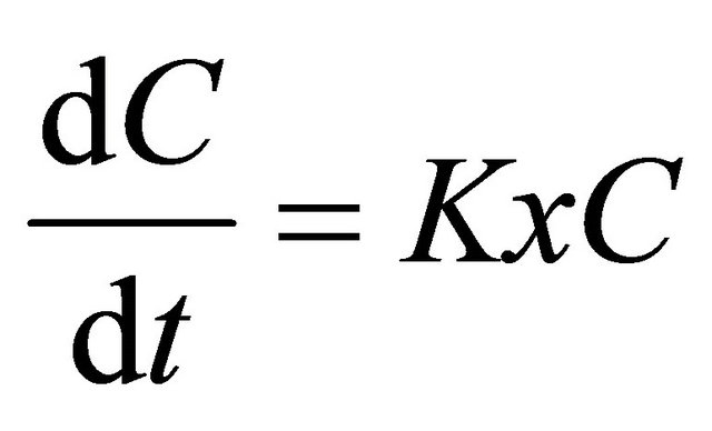 (62)
(62)
The stability of the system of reactions can be studied by obtaining the Eigen values of the K matrix. The Eigenvalues of the K matrix are obtained from the roots of the characteristic polynomial
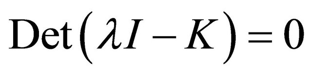 (63)
(63)
The K matrix is sparse. The polynomial form of the characteristic equation can be written as follows:
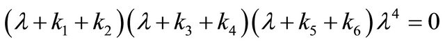 (64)
(64)
The 7 Eigenvalues are 0 repeated 4 time and
 ,
,  and
and . This system can
Table 2. Characterization of stability types.
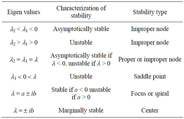
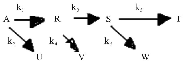
Figure 6. Scheme of 7 simultaneous reactions.
be viewed as an integrating system since all but Eigen values are negative with 4 Eigen values 0.
REFERENCES
- J. J. Craig, “Introduction to Robotics: Mechanics and Control,” 3rd Edition, Pearson Prentice Hall, Upper Saddle River, 2005.
- D. Sawyer and R. Besser, ABC World News, 20 December 2012.
- http://labintsis.com/roboti/abb-roboti/?lang=en&output=json
- K. R. Sharma, “Nanostructuing of Nanorobots for Use in Nanomedicine,” International Journal of Engineering & Technology, Vol. 2, No. 2, 2012, pp. 116-134. http://ietjournals.org/archive/2012/feb_vol_2_no_2/6686111325866989.pdf
- K. R. Sharma, “Nanostructuring Operations in Nanoscale Science and Engineering,” McGraw Hill Professional, New York, 2010.
- A. Ummat, A. Dubey and C. Mavroidis, “Bionanorobotcs: A Field Inspired by Nature,” In: Y. Bar-Cohen, Ed., Invited Chapter in CRC Handbook on Biomimetics: Mimicking and Inspiration of Biology, CRC Press, Boca Raton, 2004.
- N. A. Weir, D. P. Sierra and J. F. Jones, “A Review of Research in the Field of Nanorobotics,” Sandia Report, SAND2005-6808, Sandia National Laboratories, Albuquerque, 2005.
- A. A. G. Requicha, “Nanorobots, NEMS, and Nanoassembly,” Proceedings of the IEEE Special Issue on Nanoelectronics and Nanoprocessing, Vol. 91, No. 11, 2003, pp. 1922-1933.
- S. Shishodia, G. Sethi and B. G. Aggarwal, “Getting Back to the Roots,” Annals of the New York Academy Sciences, Vol. 1056, 2005, pp. 206-217.
- R. A. Frietas Jr., “Nanomedicine, Vol. I: Basic Capabilities,” Landes Bioscience, Georgetown, 1999.
- K. Ishiyama, M. Sendoh and K. I. Arai, “Magnetic Micromachines for Medical Applications,” Journal of Magnetism and Magnetic Materials, Vol. 242-245, 2002, pp. 1163-1165. doi:10.1016/S0304-8853(01)01293-8
- J. B. Mathieu, S. Martel, L. Yahia, G. Soulez and G. Beaudoin, “MRI Systems as a Mean of Propulsion for a Microdevice in Blood Vessels,” Proceedings of 25th Annual International Conference, IEEE Engineering in Medicine and Biology, Cancun, 17-21 September 2003.
- V. Klocke, “Nanrobot Module, Automation and Exchange,” US Patent 2010/0140473 A1, 2010.
- B. C. Regan, A. K. Zettl and S. Aloni, “Nanocrystal Powered Nanomotor,” US Patent 7863798 B2, 2011.
- D. V. Dimitrov, X. Peng, S. S. Xue and D. Wang, “Spin Oscillatory Device,” US Patent 7589600 B2, Seagate Technology, LLC, 2009.
- W. Seifert, L. I. Samuelson, B. J. Ohlsson and L. M. Borgstrom, “Directionally Controlled Growth of Nanowhiskers,” US Patent 7911035 B2, 2011.
- K. R. Sharma, “Nanorobot Drug Delivery System for Cicumin for Treatment of Alzheimer’s Disease with Increased Bioavailability during Treatment of Alzheimer’s Disease,” 68th Southwest Regional Meeting of the American Chemical Society, SWRMACS, Baton, Rouge, October-November 2012.
- W. Neuberger, “Device and Method for Photoactivated Drug Therapy,” US Patent 6397102, CeramOptec Industries, Longmeadow, 2002.
- K. R. Sharma, “Damped Wave Transport and Relaxation,” Elsevier, Amsterdam, 2005.
- R. B. Bird, W. E. Stewart and E. N. Lightfoot, “Transport Phenomena,” 2nd Edition, John Wiley, Hoboken, 2007.
- O. Levenspiel, “Chemical Reaction Engineering,” John Wiley, Hoboken, 1999.
- H. S. Mickley, T. S. Sherwood and C. E. Reed, “Applied Mathematical Methods in Chemical Engineering,” McGraw Hill Professional, New York, 1957.
- A. Varma and M. Morbidelli, “Mathematical Methods in Chemical Engineering,” Oxford University Press, Oxford, 1997.