Journal of Power and Energy Engineering, 2013, 1, 25-29
http://dx.doi.org/10.4236/jpee.2013.15004 Published Online October 2013 (http://www.scirp.org/journal/jpee)
Copyright © 2013 SciRes. JPEE
25
Fault Ride-Through Study of Wind Turbines
Xinyan Zhang1, Xuan Cao2, Weiqing Wang1, Chao Yun1
1School of Electrical Engineering, Xinjiang University, Urumqi, China; 2School of Electronics Information Engineering, China Civil
Aviation University, Tianjin, China.
Email: xjcxzxy@126.com
Received September 2013
ABSTRACT
The installation of wind energy has increased rapidly around the world. The grid codes about the wind energy require
wind turbine (WT) has the ability of fault (or low voltage) ride-through (FRT). To study the FRT operation of the wind
farms, three methods were discusse d. First, the rotor short c ur r e nt of doubly-fed induction generator (DFIG) was limited
by introducing a rotor side protection circuit. Second, the voltage of DC bus was limited by a DC energy absorb circuit.
Third, STATCOM was used to increase the low level voltages of the wind farm. Simulation under MATLAB was stu-
died and the corresponding results were given and discussed. The methods proposed in this paper can limit the rotor
short current and the DC voltage of the DFIG WT to some degree, but the vo ltage support to the power system dur ing
the fault largely depend on the installation place of STAT COM.
Keywords: Wind Energy; Fault Ride-Through; Doubly-Fed inducti on Generat or; Wi nd Farm
1. Introduction
Large scale of wind power has been installed in every
where around the world. Both the wind farm installation
capability and the WT capacity have increased rapidly.
Although the time start to use of wind power in China is
very late, the development is very fas t. There wer e many
constant speed wind turbines (CSWT) using stall control
with squirrel cage induction generators (SCIG) installed
in the wind farms in China. Newly installed WTs are
dominated by variable-speed wind turbines (VSWT) us-
ing pitch control with DFIG. VSWT with direct-driven
permanent-magnet synchronous generator (DDPSG) has
been successfully studied and installed. Now the 6MW
DDPSG WT used for the offshore wind farm has being
developed. The wind power capacities installation in China
has increased very rapidly. Figure 1 is the wind power
capacities installation in one prov ince of China.
Power system operation with increasing wind power
penetration will become more and more difficult. More
conventional power plants will be replaced by wind
farms and accordingly the stability of the power system
will be affected. So the new grid codes have proposed
even strict requirement to the wind power. Not only the
wind turbines should be kept connection in grid during
the fault and fast recover power generation after fault
clearance, but also the wind turbines or wind farm can
provide the voltage support and generate capacitive reac-
tive power [1]. To meet this requirement, there are many
researchers put their study on this subject. The studies
can be mainly divided into three categories. The first one
is mainly concern about the protection of the rotor side
converter of DFIG WT during the fault. Paper [2] has
given a through discussion about the operation process of
the rotor side crowbar of DFIG WT. Paper [3] has pro-
vided a method to improve the vector control and limit
the rotor current. Paper [4] has proposed a new magnet
excitation method to counteract the transient DC flux.
The second one is mainly concer n about how to make the
wind turbine fast recover power generation after the fault
clearance. Paper [5] has discussed some methods to pro-
tect the VSWT with DFIG and DDPSG and their fast
recover power generation capabilities. Paper [6] has stu-
died the double vector control method. Paper [7] has
made a detail study of the post-fault behavior of the
power system with wind power connected. The third one
is mainly concern the voltage and reactive power support
to the power system during the fault. Paper [8] has pro-
vided a rotor side converter reactive control. Paper [9]
has discussed the DDPSG WT FRT methods under unity,
leading and lagging power factor respectively. There are
new publications, as discussed in paper [10-12] also give
some suggestions and simulation results about the fault
ride-through of wi n d turbine generator systems.
The rotor current and DC voltage limitation is mainly
discussed in this paper. The method to give a voltage
support to power system by using STATCOM in the
wind farm is also proposed here.
Fault Ride-Through Study of Wind Turbines
Copyright © 2013 SciRes. JPEE
26
Figure 1. The WTs installation capabilities in Xinjiang of China.
2. Fault Ride-Through Requirement of WTS
The increasing and expansion of wind power has set
some new problems to power system. The power system
with large scale wind power will involve problems not
only in steady state operation but also in contingency
condition. FRT requires keep the WTs on the grid during
faults so that they can contribute to the stability to the
power transmission system. Experts have done many re-
searches about the behaviors of WTs. Figure 2(a) gives
the simulation results of the behavior of induction gene-
rator based on WT following grid faults. We can find
after 250 ms, if the fault still can not be cleared, it will
lead to voltage collapse. F igure 2(b) is the basic re-
quirements of fault ride-through of E.ON of Germany. In
the second (blue) area, the WTs should be kept on grid,
but if the WTs face overloads and stability problems,
they can short time interrupt (STI), but the STI time must
be far less than 2s.
3. Protection Measure Study of WT for FRT
Voltage drop is the most common fault occurred in the
power system. The depths of the voltage sags are differ-
ent according to the place where the fault occurrence.
The lowest depth of voltage sag can be zero. To meet the
requirement of grid for FRT of WTs, WT must keep in
grid while there is a fault in the power system, such as
single-phase ground, three-phase ground, etc. Nowadays,
the majority WTs use DFIG as electrical power generator.
The stator of DFIG is directly connected to the grid,
while its three-phase rotor windings are coupled to the
grid through a back-to-back partial size (about 20% - 30%
of the rated power of DFIG) converter. A short circuit
within the grid may lead to a 5 - 8 times of the rated sta-
tor current of DFIG. So the mechanical drive and shaft
will subject to a considerable stress. And the very high
rotor current may lead to the rotor side converter damage
(a)
(b)
Figure 2. The voltages under fault and FRT requirement, (a)
the voltages under fault with different fault clearance times,
(b) boundary conditions for FRT requireme nt .
and the DC bus over-voltage. Therefore, most measures
are proposed to protect the converter and DC bus. Ac-
tually, the stator will also end ure a high transien t current.
At present, the protection circuit of VSWTs with DFIG
mainly includes three parts. They are rotor side crowbar,
DC bus chopper and stator side crowbar used to protect
rotor side converter, DC bus and the DFIG. In this sec-
tion, we major discuss the rotor side and DC bus protec-
Fault Ride-Through Study of Wind Turbines
Copyright © 2013 SciRes. JPEE
27
tion. The block diagram is shown in Figure 3.
3.1. The Rotor Side Protection Measure
During the fault of the power system, the stator of DFIG
will endure a large fault current because it is directly
connected to the grid. The disturbance will be further
transmitted to the rotor of DFIG for the reason that the
rotor and stator is magnetically coupled and the flux must
be conservative. So the rotor current will be very high
and this may lead to over current to the rotor side con-
verter. We use IGBT and resister to make an over current
limiter (shown in Figure 3) to protect th e rotor side con-
verter. Figure 4(a) gives the simulation results of rotor
current. We can find that u se the limiter, th e rotor curr ent
can be limited within the rated range.
The DC voltage with and without rotor side over cur-
rent limiter are shown in Figures 4 (b) and (c) respec-
tively. The simulation result shows that if there is not
rotor current limiter, the DC voltage will be 1275 V
when the fault occur and it will be 1273 V when the fault
is just cleared; if there is the current limiter, the DC vol-
tage can be dropped in some degree, the value is 1260 V
when the fault occur and is 1242 V when the fault is just
cleared. So there is still a 5% over voltage.
3.2. The DC Bus Protection Measure
Use When the fault (s hor t circuit) occurs, the voltage will
drop considerably and the depth is zero in the place
where the fault is located. In the fault moment, the grid
side converter (GS C) lost its ability to transfer the pow er
from the rotor side converter (RSC) to the grid, but the
WT is still driven by the wind energy, so there will be a
lot of energy gathered in the DC part of the back-to-back
power electronic converter. This will make the DC capa-
citor be over charged and consequently the voltage of the
DC bus will be very high. Use the rotor current limiter,
the transient over current can b e reduced, this will lead to
the drop of the DC over voltage. But just as discussed in
subsection A of this section, the DC bus still has a con-
siderable over voltage. So we introduce a DC voltage
limiter by using the chopper shown in Figure 2 to absorb
the additional energy. Figure 5 shows the simulation
result of the DC voltage while th e DC over voltage limi-
ter is used. It can be found the over voltage has been re-
duced from 1300 kV to 1235 kV, but there is still 3% at
the moment when the fault is cleared. And the voltage
drop can not be removed.
4. Voltage Support
Conventional synchronous generator is able to supply
high short-circuit current to the fault location and holds
the voltage in the power system so the low voltage area
be reduced. As the increasing of the wind power penetra-
Figure 3. The block diagram of protection measure for FRT
of DFIG WT.
(a)
(b)
(c)
Figure 4. The simulation results of rotor current and DC
voltage of DFIG WT, (a) the rotor current during fault; (b)
the DC voltage without rotor current limitation; (c) the DC
voltage with rotor current limitation.
Figure 5. Simulation result of the DC voltage with DC over
voltage limiter.
Fault Ride-Through Study of Wind Turbines
Copyright © 2013 SciRes. JPEE
28
tion in power system more and mor e conventional power
will be replaced by the wind power. So the wind farm
must have the ability to give the power system voltage
support during the fault condition. There are some re-
searches in this aspect. One is major in study how to
control the reactive current and then let the WT has the
ability to generate reactive power. The other is major in
how to improve the voltage of the wind farm and give
reactive power to the system at the same time. Because
the reactive power generated by the WT is limited, more
attention now is drawn to improve the voltage by use
FACTS, especially in the condition that th e wind farm is
built by SCIG WTs for the reason that this kind of WTs
can not generate reactive power by the control within the
generator.
We use a simplified system of a power system with
wind farm shown in Figure 6 to study the voltage sup-
port of the wind farm by using STATCOM, because
STATCOM not only can improve the voltage level but
also can generate both lagging and leading reactive pow-
er. In Figure 6, LV means low level voltage, MV means
middle le ve l v oltage, H V means high l evel volt a ge.
Figure 7 shows the simulation result when the wind
farm is built by DFIG WTs.
From Figure 7(a), we can find using STATCOM the
absorbed reactive power can be reduced, especially at the
moment that the fault is occurred and cleared. Figure 7(b)
shows the LV voltage condition while there is fault. From
this result, we find the voltage can be increased. But at
the moment the fault is cleared, the voltage has more
than 10% over voltage. Figure 7(c) shows the LV vol-
tage condition while there is serious voltage dip. From
this result, we find the voltage can be increased to 90%
of the rated voltage level. But at the moment the fault is
cleared, the voltage has also nearly 10% over voltage.
About this problem we need further study in future.
Figure 8 shows the simulation result when the wind
farm is built by SCIG WTs.
Figure 8(a) shows the LV voltage and MV voltage
when there is fault occurred in the power system; Figure
8(b) shows the voltages of LV bus and MV bus while th e
STATCOM is connected in the MV bus during the fault;
Figure 8(c) shows the voltages of LV bus and MV bus
while the STATCOM is connected in the LV bus during
the fault. From the simulation results, we can find using
STATCOM the voltage s of both LV bus and MV bus can
be increased. But the voltage amplitudes increased are
different according to the place where STATCOM lo-
cated. STATCOM connected to the LV bus is better for
the wind farm.
Figure 6. The power system with wind farm.
(a)
(b)
(c)
Figure 7. Simulation result under fault condition when the
wind farm is built by DFIG WTs, (a) the reactive power of
the wind farm during the voltage dip, (b)the LV voltage of
the wind farm during the serious voltage dip.
5. Conclusion
The power system fault will lead to voltage dip on WTs.
To maintain the grid stability, wind farm is required to
keep connected in the power system for a defined time
period under grid fault, this is called FRT. Actually, the
voltage is not always dip to zero, it can be just a voltage
sag. So many researchers put their efforts to deal with the
so called low voltage ride-through problem. The main
differences in FRTs requirement of different countries
are the depth of voltage drop, the time period and the
boundary where WTs can be tripped. New FRT needs
not only the WTs keep on grid but also can provide vol-
tage support or generator reactive power to the power
system. So nowad ays, the FRT researchers care even more
subjects. How to protect the converter and DC bus of
WTs, how to control the generator to generate reactive
power and how to increase the voltage under grid fault
are the three main study directions.
6. Acknowledgements
The work is supported by NSFC of Xinjiang of China
(No. 2011211A016) and Doctor Project of Xinjiang Uni-
Fault Ride-Through Study of Wind Turbines
Copyright © 2013 SciRes. JPEE
29
(a)
(b)
(c)
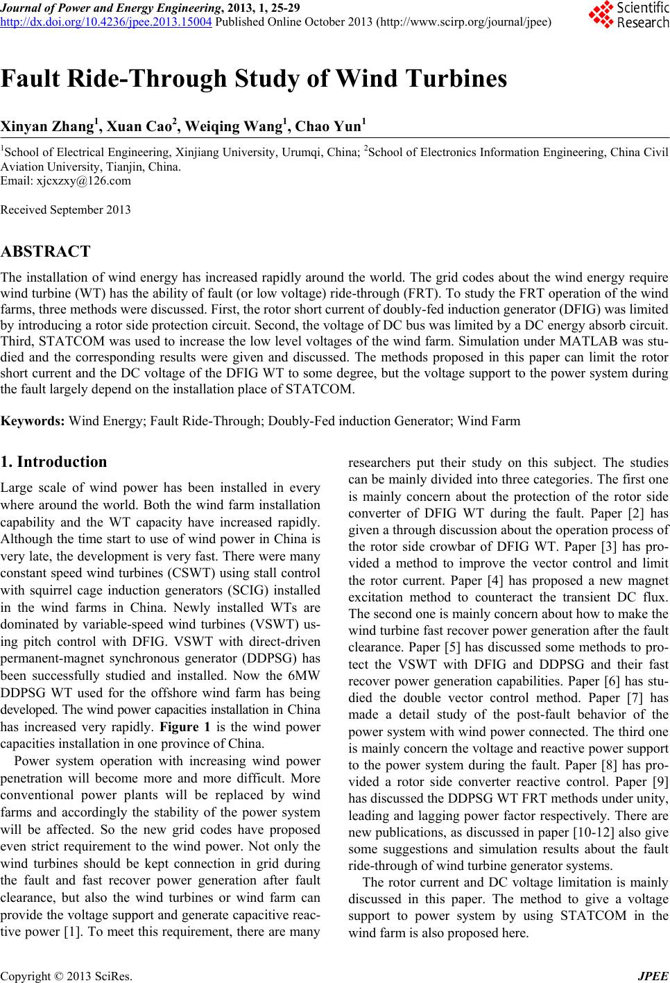
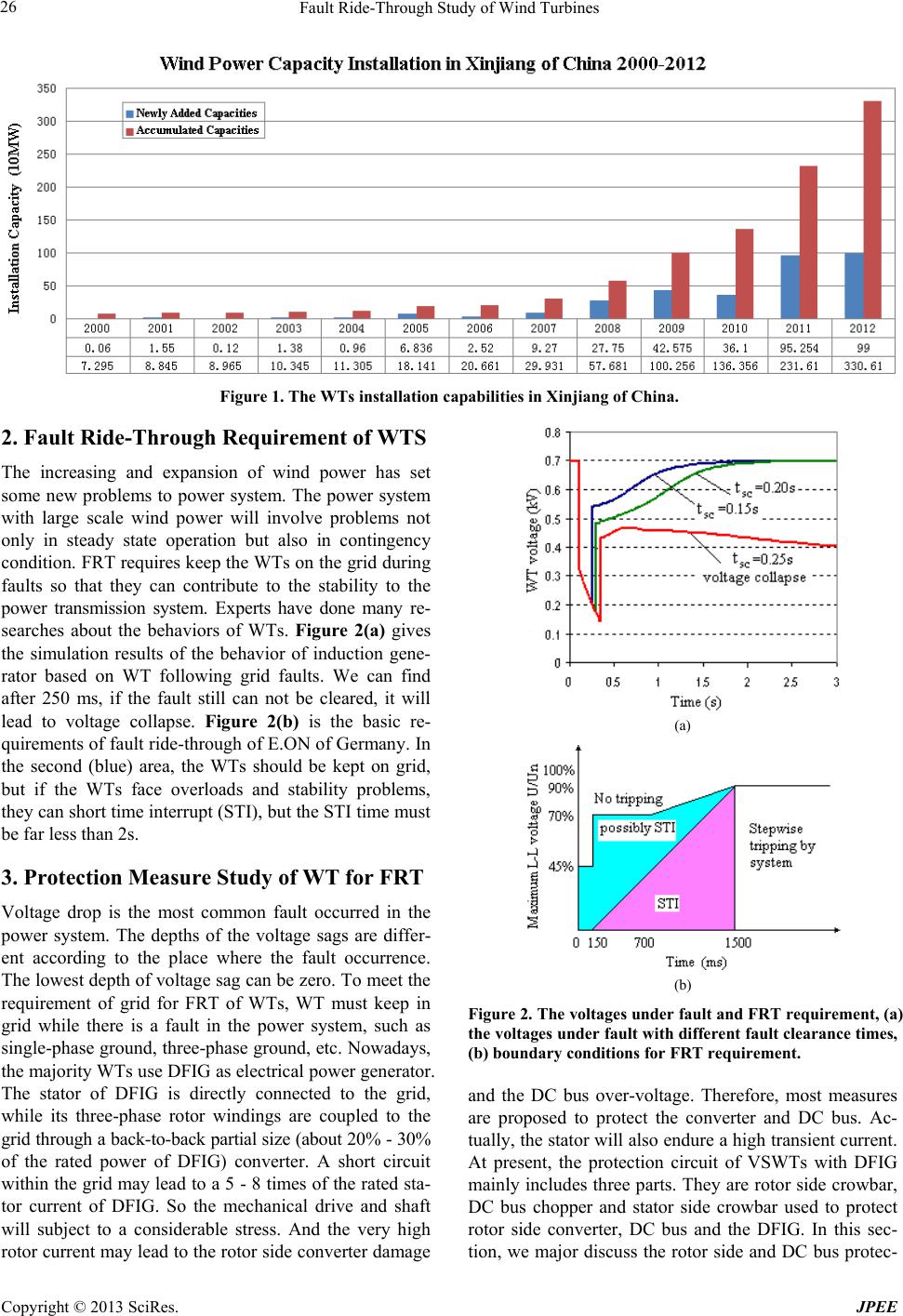
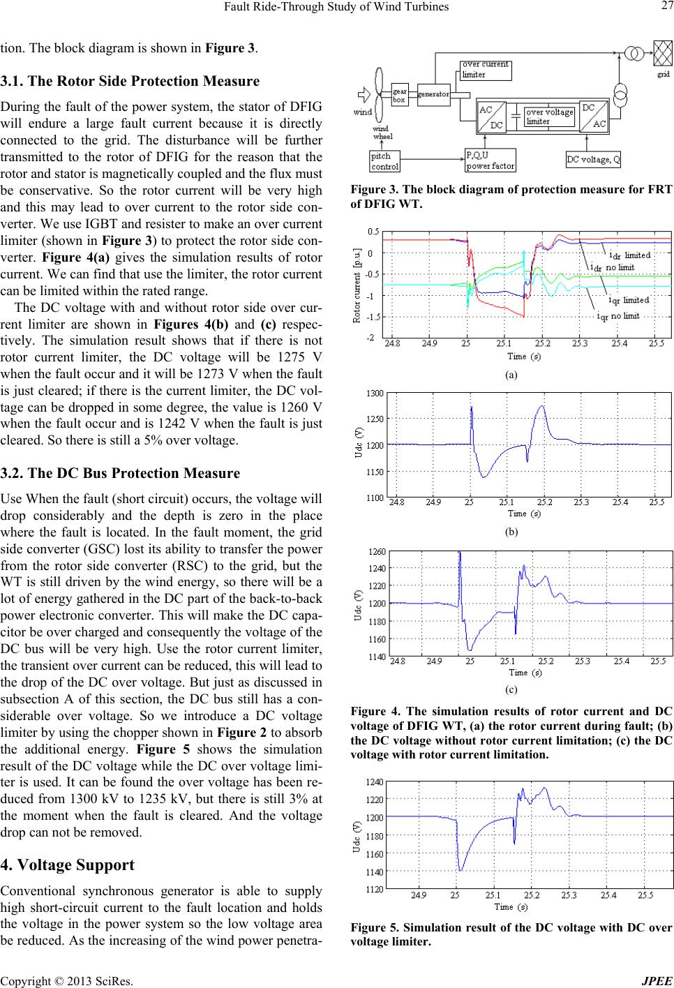
Figure 8. The LV and MV voltage of system shown in Fig-
ure 6 under fault when wind farm is built by SCIG WTs, (a)
without STATCOM, (b) STATCOM connected in the MV
bus, (c) STATCOM connected in LV bus.
versity (No. BS100122) .
REFERENCES
[1] I. Erlich, W. Winter and A. Dittrich, “Advanced Grid
Requirement for the Integration of Wind Turbines into the
German Transmission System,” IEEE Powertech Confe-
rence Proceedings, St. Petersburg, Russia, 27-30 June,
2006, pp.1210-1216.
[2] A. D. Hansen and C. Michalke, “Fault Ride-through Ca-
pability of DFIG Wind Turbines,Renewable Energy,
Vol. 32, No. 8, 2007, pp. 1594-1610.
http://dx.doi.org/10.1016/j.renene.2006.10.008
[3] J. B. Hu, D. Sun, Y. K. He and R.-D. Zhao, “Modeling
and Control of DFIG Wind Energy Generation System
under Grid Voltage Dip”, Automation of Electric Power
Systems, Vol. 30, No. 8, 2006, pp. 21-26.
[4] D. W. Xiang, S. C. Yang and L. Ran, “Magnet Exc itation
Control Strategy of D FIG on Grid Operatio n during Power
System Symmetric Faul t,” Proceedings of the CSE E, Vol.
26, No. 3, 2006, pp. 164-169.
[5] S. J. Hu, J. L. Li and H. H. Xu, “Analysis on Protection
Circuits Suitable for VSCF-WECS to Cope with Grid
Faults,Commutation Technology and Power Draw, No.
1, 2008, pp. 45-50.
[6] X. P. Zhang, “Performance of PWM Rectifier under Vol-
tage Dips in Wind Power,Electrical Application, Vol.
28, No. 9, 2007, pp. 52-56.
[7] C. Jauch, P. Sorensen, I. Norheim and C. Rasmussen,
Simulation of the Impact of Wind Power on the Tran-
sient Fault Behavior of the Nordic Power System,Elec-
tric Power System Research, Vol. 77, 2007, pp. 135-144.
[8] I. E rlich, C. Feltes, F. Shewarega and M. Wilch, “Interac-
tion of Large Offshore Wind Parks with the Electrical
Grid,Proceedings of DRPT 2008, Nanjing, China, 3-5
April, 2008, pp. 1242-1250.
[9] S. J. Hu, J. L. Li and H. H. Xu, “Analysis on the Low-
Voltage-Ride-Through Capability of Direct-Drive Perma-
nent Magnetic Generator Wind Turbines,” Automation of
Electric Power Systems, Vol. 31, No. 17, 2007, pp. 73-77.
[10] D. Campos-Gaona, E. Moreno-Goytia and O. Anaya-Lara,
“Fault Ride-Through Improvement of DFIG-WT by Inte-
grating a Two-Degrees-of-Freedom Internal Model Con-
trol,” IEEE Transactions on Industrial Electronics, Vol.
60, No. 3, 2013, pp. 1133-1145.
[11] R. L. Hendriks, R. Völzke and W. L. Kling, “Fault Ride-
Through Strategies for VSC-Connected Wind Parks,”
Europes Premier Wind Energy Event, Marseille, France,
16-19 March 2009, pp. 252-260.
[12] A. Arulampalam, G. Ramtharan, N. Caliao, J. B. Eka-
nayake and N. Jenkins, “Simulated Onshore-Fault Ride
through of Offshore Wind Farms Connected through VSC
HVDC,Wind Engineering, Vol. 32, No. 2, 2008, pp.
103-113.