Paper Menu >>
Journal Menu >>
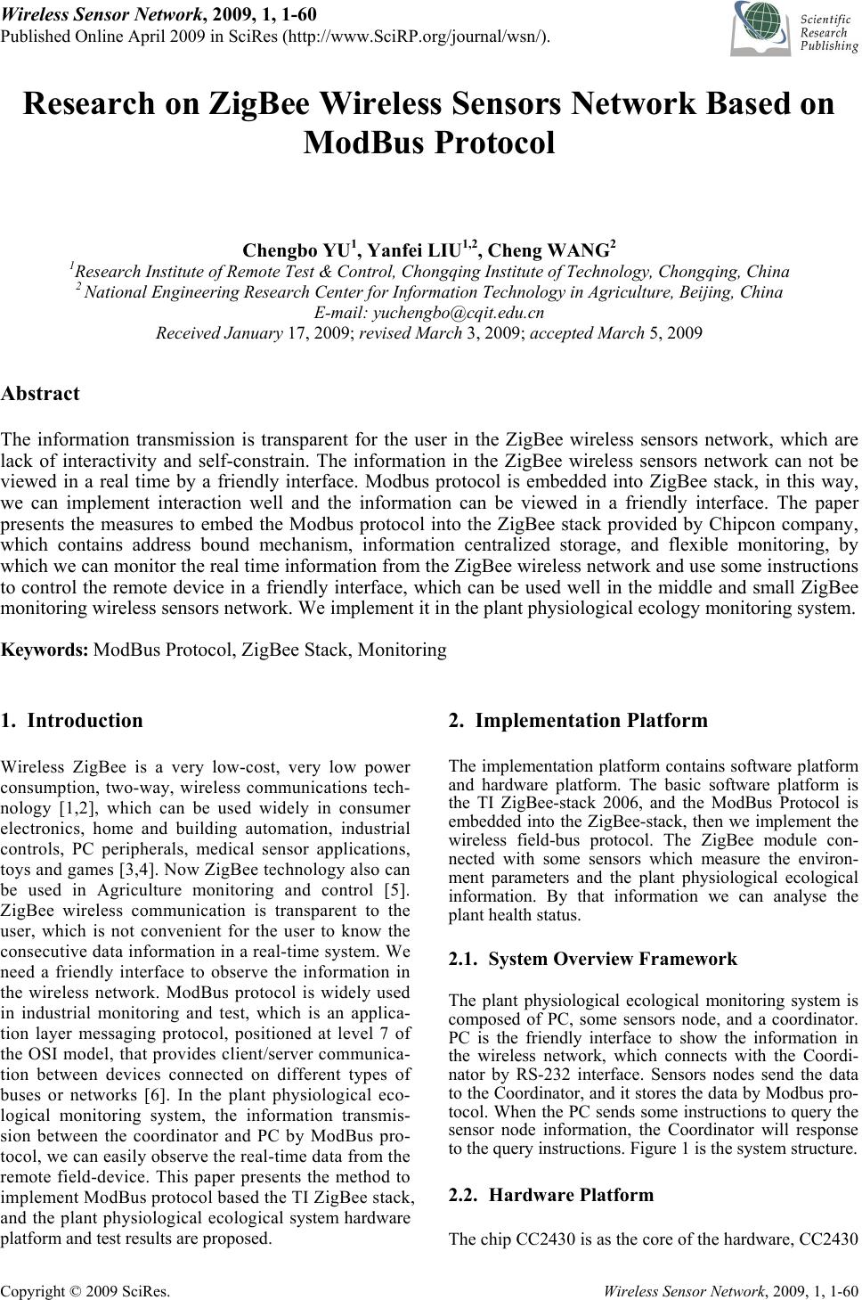 Wireless Sensor Network, 2009, 1, 1-60 Published Online April 2009 in SciRes (http://www.SciRP.org/journal/wsn/). Copyright © 2009 SciRes. Wireless Sensor Network, 2009, 1, 1-60 Research on ZigBee Wireless Sensors Network Based on ModBus Protocol Chengbo YU1, Yanfei LIU1,2, Cheng WANG2 1Research Institute of Remote Test & Control, Chongqing Institute of Technology, Chongqing, China 2 National Engineering Research Center for Information Technology in Agriculture, Beijing, China E-mail: yuchengbo@cqit.edu.cn Received January 17, 2009; revised March 3, 2009; accepted March 5, 2009 Abstract The information transmission is transparent for the user in the ZigBee wireless sensors network, which are lack of interactivity and self-constrain. The information in the ZigBee wireless sensors network can not be viewed in a real time by a friendly interface. Modbus protocol is embedded into ZigBee stack, in this way, we can implement interaction well and the information can be viewed in a friendly interface. The paper presents the measures to embed the Modbus protocol into the ZigBee stack provided by Chipcon company, which contains address bound mechanism, information centralized storage, and flexible monitoring, by which we can monitor the real time information from the ZigBee wireless network and use some instructions to control the remote device in a friendly interface, which can be used well in the middle and small ZigBee monitoring wireless sensors network. We implement it in the plant physiological ecology monitoring system. Keywords: ModBus Protocol, ZigBee Stack, Monitoring 1. Introduction Wireless ZigBee is a very low-cost, very low power consumption, two-way, wireless communications tech- nology [1,2], which can be used widely in consumer electronics, home and building automation, industrial controls, PC peripherals, medical sensor applications, toys and games [3,4]. Now ZigBee technology also can be used in Agriculture monitoring and control [5]. ZigBee wireless communication is transparent to the user, which is not convenient for the user to know the consecutive data information in a real-time system. We need a friendly interface to observe the information in the wireless network. ModBus protocol is widely used in industrial monitoring and test, which is an applica- tion layer messaging protocol, positioned at level 7 of the OSI model, that provides client/server communica- tion between devices connected on different types of buses or networks [6]. In the plant physiological eco- logical monitoring system, the information transmis- sion between the coordinator and PC by ModBus pro- tocol, we can easily observe the real-time data from the remote field-device. This paper presents the method to implement ModBus protocol based the TI ZigBee stack, and the plant physiological ecological system hardware platform and test results are proposed. 2. Implementation Platform The implementation platform contains software platform and hardware platform. The basic software platform is the TI ZigBee-stack 2006, and the ModBus Protocol is embedded into the ZigBee-stack, then we implement the wireless field-bus protocol. The ZigBee module con- nected with some sensors which measure the environ- ment parameters and the plant physiological ecological information. By that information we can analyse the plant health status. 2.1. System Overview Framework The plant physiological ecological monitoring system is composed of PC, some sensors node, and a coordinator. PC is the friendly interface to show the information in the wireless network, which connects with the Coordi- nator by RS-232 interface. Sensors nodes send the data to the Coordinator, and it stores the data by Modbus pro- tocol. When the PC sends some instructions to query the sensor node information, the Coordinator will response to the query instructions. Figure 1 is the system structure. 2.2. Hardware Platform The chip CC2430 is as the core of the hardware, CC2430 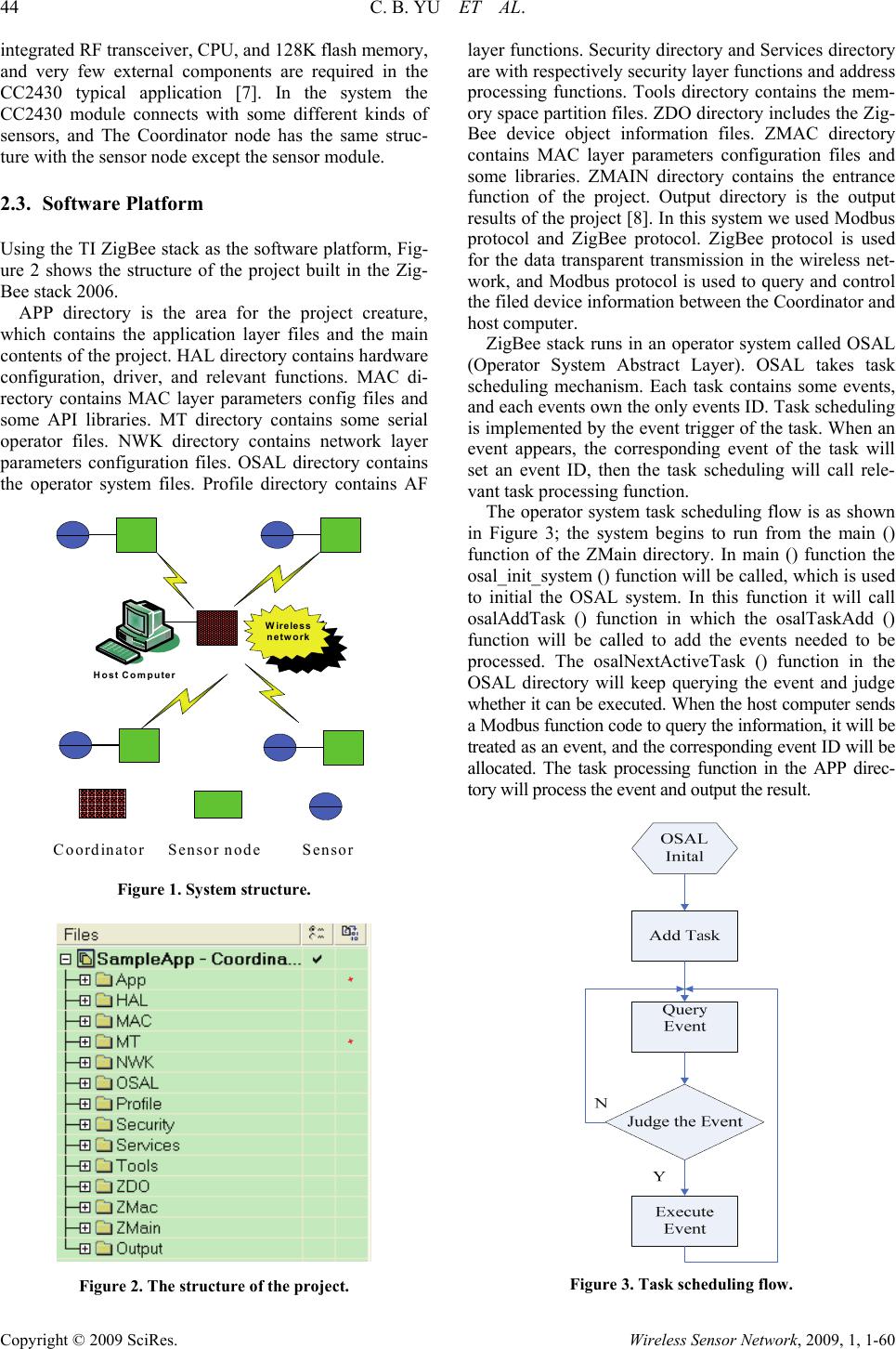 44 C. B. YU ET AL. Copyright © 2009 SciRes. Wireless Sensor Network, 2009, 1, 1-60 integrated RF transceiver, CPU, and 128K flash memory, and very few external components are required in the CC2430 typical application [7]. In the system the CC2430 module connects with some different kinds of sensors, and The Coordinator node has the same struc- ture with the sensor node except the sensor module. 2.3. Software Platform Using the TI ZigBee stack as the software platform, Fig- ure 2 shows the structure of the project built in the Zig- Bee stack 2006. APP directory is the area for the project creature, which contains the application layer files and the main contents of the project. HAL directory contains hardware configuration, driver, and relevant functions. MAC di- rectory contains MAC layer parameters config files and some API libraries. MT directory contains some serial operator files. NWK directory contains network layer parameters configuration files. OSAL directory contains the operator system files. Profile directory contains AF Coordinator Sensor node Host Computer Wireless network Sensor Figure 1. System structure. Figure 2. The structure of the project. layer functions. Security directory and Services directory are with respectively security layer functions and address processing functions. Tools directory contains the mem- ory space partition files. ZDO directory includes the Zig- Bee device object information files. ZMAC directory contains MAC layer parameters configuration files and some libraries. ZMAIN directory contains the entrance function of the project. Output directory is the output results of the project [8]. In this system we used Modbus protocol and ZigBee protocol. ZigBee protocol is used for the data transparent transmission in the wireless net- work, and Modbus protocol is used to query and control the filed device information between the Coordinator and host computer. ZigBee stack runs in an operator system called OSAL (Operator System Abstract Layer). OSAL takes task scheduling mechanism. Each task contains some events, and each events own the only events ID. Task scheduling is implemented by the event trigger of the task. When an event appears, the corresponding event of the task will set an event ID, then the task scheduling will call rele- vant task processing function. The operator system task scheduling flow is as shown in Figure 3; the system begins to run from the main () function of the ZMain directory. In main () function the osal_init_system () function will be called, which is used to initial the OSAL system. In this function it will call osalAddTask () function in which the osalTaskAdd () function will be called to add the events needed to be processed. The osalNextActiveTask () function in the OSAL directory will keep querying the event and judge whether it can be executed. When the host computer sends a Modbus function code to query the information, it will be treated as an event, and the corresponding event ID will be allocated. The task processing function in the APP direc- tory will process the event and output the result. Figure 3. Task scheduling flow. 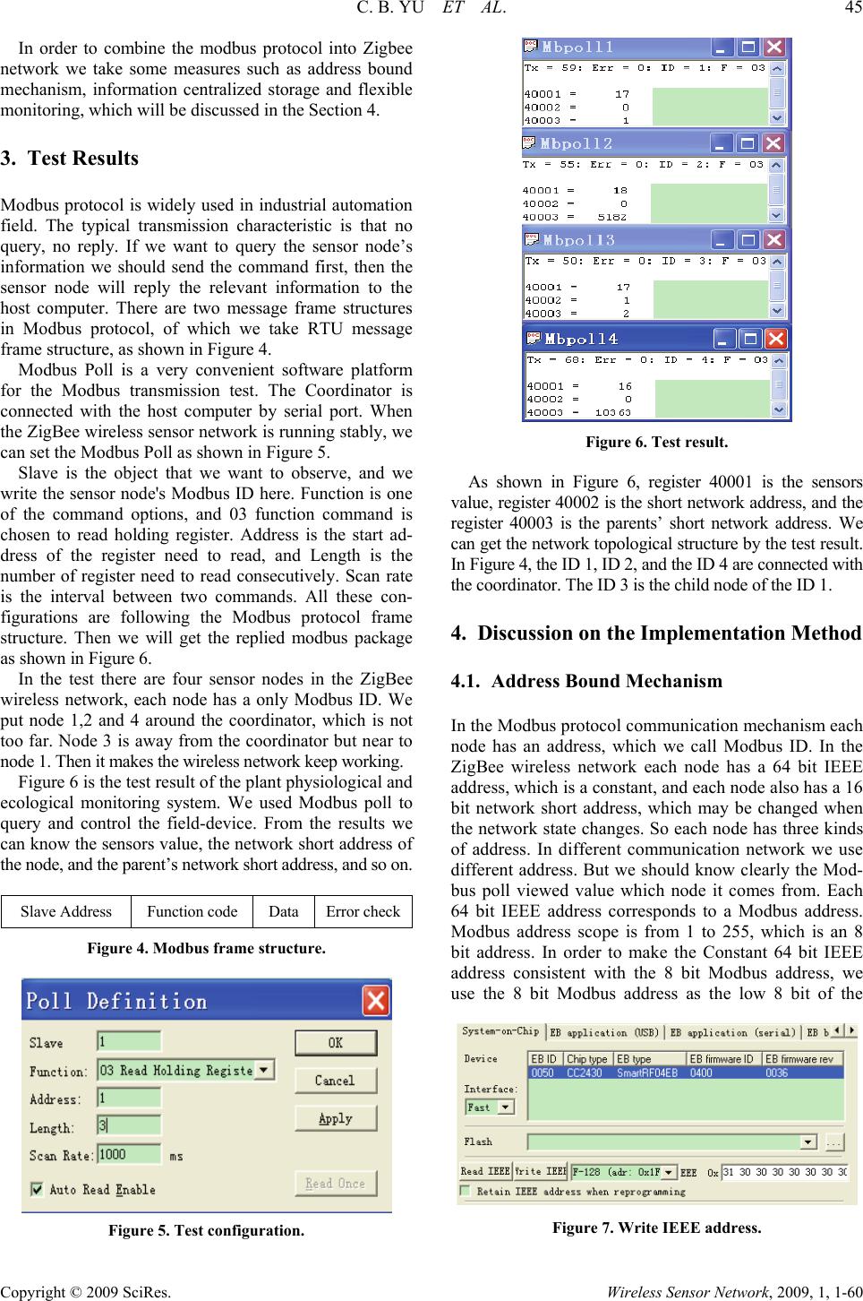 C. B. YU ET AL. 45 Copyright © 2009 SciRes. Wireless Sensor Network, 2009, 1, 1-60 In order to combine the modbus protocol into Zigbee network we take some measures such as address bound mechanism, information centralized storage and flexible monitoring, which will be discussed in the Section 4. 3. Test Results Modbus protocol is widely used in industrial automation field. The typical transmission characteristic is that no query, no reply. If we want to query the sensor node’s information we should send the command first, then the sensor node will reply the relevant information to the host computer. There are two message frame structures in Modbus protocol, of which we take RTU message frame structure, as shown in Figure 4. Modbus Poll is a very convenient software platform for the Modbus transmission test. The Coordinator is connected with the host computer by serial port. When the ZigBee wireless sensor network is running stably, we can set the Modbus Poll as shown in Figure 5. Slave is the object that we want to observe, and we write the sensor node's Modbus ID here. Function is one of the command options, and 03 function command is chosen to read holding register. Address is the start ad- dress of the register need to read, and Length is the number of register need to read consecutively. Scan rate is the interval between two commands. All these con- figurations are following the Modbus protocol frame structure. Then we will get the replied modbus package as shown in Figure 6. In the test there are four sensor nodes in the ZigBee wireless network, each node has a only Modbus ID. We put node 1,2 and 4 around the coordinator, which is not too far. Node 3 is away from the coordinator but near to node 1. Then it makes the wireless network keep working. Figure 6 is the test result of the plant physiological and ecological monitoring system. We used Modbus poll to query and control the field-device. From the results we can know the sensors value, the network short address of the node, and the parent’s network short address, and so on. Slave Address Function code Data Error check Figure 4. Modbus frame structure. Figure 5. Test configuration. Figure 6. Test result. As shown in Figure 6, register 40001 is the sensors value, register 40002 is the short network address, and the register 40003 is the parents’ short network address. We can get the network topological structure by the test result. In Figure 4, the ID 1, ID 2, and the ID 4 are connected with the coordinator. The ID 3 is the child node of the ID 1. 4. Discussion on the Implementation Method 4.1. Address Bound Mechanism In the Modbus protocol communication mechanism each node has an address, which we call Modbus ID. In the ZigBee wireless network each node has a 64 bit IEEE address, which is a constant, and each node also has a 16 bit network short address, which may be changed when the network state changes. So each node has three kinds of address. In different communication network we use different address. But we should know clearly the Mod- bus poll viewed value which node it comes from. Each 64 bit IEEE address corresponds to a Modbus address. Modbus address scope is from 1 to 255, which is an 8 bit address. In order to make the Constant 64 bit IEEE address consistent with the 8 bit Modbus address, we use the 8 bit Modbus address as the low 8 bit of the Figure 7. Write IEEE address. 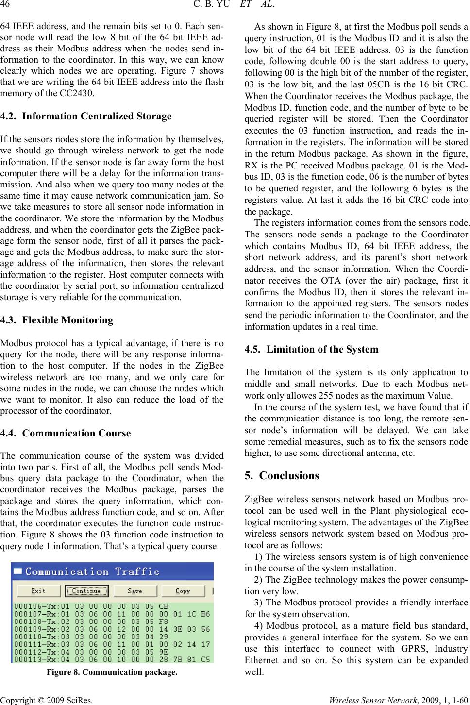 46 C. B. YU ET AL. Copyright © 2009 SciRes. Wireless Sensor Network, 2009, 1, 1-60 64 IEEE address, and the remain bits set to 0. Each sen- sor node will read the low 8 bit of the 64 bit IEEE ad- dress as their Modbus address when the nodes send in- formation to the coordinator. In this way, we can know clearly which nodes we are operating. Figure 7 shows that we are writing the 64 bit IEEE address into the flash memory of the CC2430. 4.2. Information Centralized Storage If the sensors nodes store the information by themselves, we should go through wireless network to get the node information. If the sensor node is far away form the host computer there will be a delay for the information trans- mission. And also when we query too many nodes at the same time it may cause network communication jam. So we take measures to store all sensor node information in the coordinator. We store the information by the Modbus address, and when the coordinator gets the ZigBee pack- age form the sensor node, first of all it parses the pack- age and gets the Modbus address, to make sure the stor- age address of the information, then stores the relevant information to the register. Host computer connects with the coordinator by serial port, so information centralized storage is very reliable for the communication. 4.3. Flexible Monitoring Modbus protocol has a typical advantage, if there is no query for the node, there will be any response informa- tion to the host computer. If the nodes in the ZigBee wireless network are too many, and we only care for some nodes in the node, we can choose the nodes which we want to monitor. It also can reduce the load of the processor of the coordinator. 4.4. Communication Course The communication course of the system was divided into two parts. First of all, the Modbus poll sends Mod- bus query data package to the Coordinator, when the coordinator receives the Modbus package, parses the package and stores the query information, which con- tains the Modbus address function code, and so on. After that, the coordinator executes the function code instruc- tion. Figure 8 shows the 03 function code instruction to query node 1 information. That’s a typical query course. Figure 8. Communication package. As shown in Figure 8, at first the Modbus poll sends a query instruction, 01 is the Modbus ID and it is also the low bit of the 64 bit IEEE address. 03 is the function code, following double 00 is the start address to query, following 00 is the high bit of the number of the register, 03 is the low bit, and the last 05CB is the 16 bit CRC. When the Coordinator receives the Modbus package, the Modbus ID, function code, and the number of byte to be queried register will be stored. Then the Coordinator executes the 03 function instruction, and reads the in- formation in the registers. The information will be stored in the return Modbus package. As shown in the figure, RX is the PC received Modbus package. 01 is the Mod- bus ID, 03 is the function code, 06 is the number of bytes to be queried register, and the following 6 bytes is the registers value. At last it adds the 16 bit CRC code into the package. The registers information comes from the sensors node. The sensors node sends a package to the Coordinator which contains Modbus ID, 64 bit IEEE address, the short network address, and its parent’s short network address, and the sensor information. When the Coordi- nator receives the OTA (over the air) package, first it confirms the Modbus ID, then it stores the relevant in- formation to the appointed registers. The sensors nodes send the periodic information to the Coordinator, and the information updates in a real time. 4.5. Limitation of the System The limitation of the system is its only application to middle and small networks. Due to each Modbus net- work only allowes 255 nodes as the maximum Value. In the course of the system test, we have found that if the communication distance is too long, the remote sen- sor node’s information will be delayed. We can take some remedial measures, such as to fix the sensors node higher, to use some directional antenna, etc. 5. Conclusions ZigBee wireless sensors network based on Modbus pro- tocol can be used well in the Plant physiological eco- logical monitoring system. The advantages of the ZigBee wireless sensors network system based on Modbus pro- tocol are as follows: 1) The wireless sensors system is of high convenience in the course of the system installation. 2) The ZigBee technology makes the power consump- tion very low. 3) The Modbus protocol provides a friendly interface for the system observation. 4) Modbus protocol, as a mature field bus standard, provides a general interface for the system. So we can use this interface to connect with GPRS, Industry Ethernet and so on. So this system can be expanded well.  C. B. YU ET AL. 47 Copyright © 2009 SciRes. Wireless Sensor Network, 2009, 1, 1-60 6. Acknowledgment The work is supported by the foundation of National Key Technology R&D Program (2006BAD11A10, 2006BAD 30B03), and is supported by the foundation of chongqing natural science (CSTC2007BA2023). 7. References [1] IEEE STD 802.15.4 [S], http://www.zigbee.org. [2] ZigBee Alliance, ZigBee Specification [Z], http://www. ZigBee. org. [3] L. T. Cao, W. Jiang, and Z. L. Zhang, “Networked wireless meter reading system based on ZigBee technology,” Control and Decision Conference, Chinese, pp. 3455-3460, 2008. [4] W. K. Park, C. S. Choi, J. Han, and I. Han, “Design and implementation of ZigBee based URC applicable to legacy home appliances,” Consumer Electronics, ISCE 2007, IEEE International Symposium, pp. 1-6, 2007. [5] Y. M. Zhou, X. L. Yang, X. S. Guo, M. G. Zhou, and L. R. Wang, “A design of greenhouse monitoring & control system based on ZigBee wireless sensor network,” Wireless Communications, Networking and Mobile Computing, WiCom 2007, International Conference, pp. 2563-2567, 2007. [6] Modbus Application Protocol Specification [S], http:// www.Modbus-IDA.org. [7] Texas Instruments, Datasheet, CC2430[Z], http://www.ti.com. [8] WXL. Zigbee Stack User Guide [Z], http://www.C51rf.com. |