Energy and Power Engineering, 2013, 5, 1517-1520
doi:10.4236/epe.2013.54B287 Published Online July 2013 (http://www.scirp.org/journal/epe)
Performance Assessment of Islanding Detection for Mul-
ti-inverter Grid-connected Photovoltaic Systems
Xing Zhang, Dong Xie
College of Electric and Automation, Hefei University of Technology, Hefei, China
Email: XDY@tlu.edu.cn, xiedong1018@yahoo.com.cn
Received 2013
ABSTRACT
Islanding detection is an essential function for safety and reliability in grid-connected Distributed Generation Systems
(DGS). Passive and active islanding detection methods have been analyzed in literature considering DGS with only one
inverter connected to the utility. With the big scale application of photovoltaic (PV) power systems, islanding detection
technology of multi-inverter DGS has been paid more attention. This paper analyzes the performance of diverse island-
ing detection methods in multiple inverters grid-connected PV systems. Non-Detection Zones (NDZ) of multi-inverter
systems in a load parameter space are used as analytical tool. The paper provides guidance for the islanding detection
design in multiple grid-connected inverters.
Keywords: Photovoltaic Power Systems; Islanding Detection; Multi-inverter; Non-Detection Zones
1. Introduction
One problem for photovoltaic (PV) power system is is-
landing effect. When the grid is tripped for breakdown or
overhaul, the PV system remains independent running
status connected with the local load, this kind of phe-
nomenon is called the islanding effect. This phenomenon
will threaten the safety of power maintainer and power
equipment. Therefore, the PV system must have island-
ing detection function to prevent the occurrence of is-
landing effect [1-2].
Two types of islanding detection methods (IDMs), the
passive and active methods, have so far been developed.
Among them, the active methods include Active Fre-
quency Drifting (AFD) method, Active Frequency Drift-
ing with Positive-Feedback (AFDPF) method, Slip-
Mode Frequency Shifting (SMS) method and so on. Now
the researches on IDM are mostly in single-inverter PV
systems. With the development of economy and tech-
nology, multi-inverter PV systems will be used more
extensively. So the researchers have paid more attention
to the IDMs of multi-inverter systems. According to the
analysis of non-detection zones (NDZs) in Qf×f0
frame[3], this paper investigates the performance of
IDMs in multi- inverter PV systems, so as to provide a
reference for the islanding detection design in multiple
grid-connected inverters.
2. Performance Analysis of Idms for Mul-
ti-Inverter Operating in Parallel
2.1. Part of Inverters Adopt Passive IDMs
The inverters in grid-connected PV systems usually use
sinusoidal current control model based on the unit power
factor [4]. So, in multi-inverter systems, the
grid-connected inverters equipped with passive IDMs
can be regard as a negative resistance which transport the
active power to grid, the negative resistance together
with the local load is equivalent to resistance Req, i.e.
1
eq
R
Rk
(1)
where R is the local load, k is the proportion of active
power which is output by inverters equipped with passive
IDMs relative to overall active power consumed by the
local load. After the equivalent disposal, Req's quality
factor Qfeq may be represented as:
01
f
feq eq
Q
QRC
k

(2)
where Qf is the original quality factor of the local load. It
can be shown that Req's quality factor equals to 1/(1-k)
times of Qf . That is to say, if the inverters equipped with
passive IDMs provide 50% active power to local load (k
= 0.5), the equivalent quality factor Qfeq equals to
2Qf .Thus, if the single-inverter systems equipped with
active IDMs can successfully detect the islanding when
Qf 2.5, the multi-inverter systems can detect the is-
landing only if Qf 1.25, this means the NDZ has shifted
towards the left. Obviously, this kind of situation in-
Copyright © 2013 SciRes. EPE
X. ZHANG, D. XIE
1518
creased the probability of islanding occurrence.
2.2. Inverters Equipped with AFD and SMS
IDMs
Taking two grid-connected inverters for example, sup-
pose that the proportion of active power for the local load
provided by the inverter equipped with AFD IDM is
KAFDpu, and then the proportion of active power provided
by the inverter equipped with SMS IDM is (1-KAFDpu).
Therefore, the two inverter’s current is
2sin(2
AFD AFDpuAFD
iKIft

) (3)
2(1) sin(2)
SMS AFDpuSMS
iKIft

 (4)
where θAFD is the current initial phase angle of the in-
verter equipped with AFD IDM, andθSFS is the current
initial phase angle of the inverter equipped with SMS
IDM[5-6]. As per definition:
(2) 2
Z
AFD
t
f
f
f
f
 

 (5)
where tz is the dead area time inserted into the output
current of inverter equipped with AFD IDM, f is the last
period frequency of inverter output voltage, Δf is the
frequency shifting of inverter output voltage;
sin 2
g
SMS m
mg
f
f
f
f


 

(6)
whereθm is the maximum phase shifting of output cur-
rent of inverter equipped with SMS IDM, fm is frequency
when θm arise, fg is the frequency of grid, f is the last
period frequency of inverter output voltage.
According to (3) and (4), if the two parallel inverters
are equivalent to one inverter, the initial phase angle of
equivalent inverter’s total output current is
1sin(1) sin
tan()
cos(1) cos
AFDpu AFDAFDpuSMS
INV
AFDpu AFDAFDpuSMS
KK
KK



(7)
Thus, the NDZ in Qf×f 0 frame is determined by the
criteria as follows

02
20
tan( )0
INV
f
ff
ff
Q
f
(8)
IfΔf in AFD IDM is 1Hz,θm is 10° and( fm – fg) is 3Hz
in SMS IDM, the sketch map of NDZ for PV system
with both AFD and SMS IDMs is shown in Figure 1.
There one sees that the NDZ is enlarged along with the
augment of KAFDpu, which proportion of local load’s ac-
tive power provided by the inverter equipped with AFD
IDM.
Figure 1. NDZ of a system with both AFD and SMS IDMs.
2.3. Inverters equipped with AFD and AFDPF
IDMs
The AFD IDM shifts the system operating frequency
towards the enhanced direction without considering if the
local load is capacitor or inductor. But the AFDPF IDM
will shift system operating frequency towards enhanced
or descended direction, which is decided by local load’s
capacitive or inductive characteristic. Therefore, the mul-
ti-inverter PV systems equipped with both AFD IDM and
AFDPF IDM, will have mutual influence.
Still taking two grid-connected inverters for example,
suppose that the proportion of active power for the local
load provided by the inverter equipped with AFD IDM is
KAFDpu, and then the proportion of active power provided
by the inverter equipped with AFDPF IDM is (1-KAFDpu).
Therefore the two inverter’s current is [7]
AFD
2sin[2
AFD AFDpu
iKIft

] (9)
AFDPF AFDPF
2(1) sin(2)
AFDpu
iKIft

 (10)
where θAFD is the current initial phase angle of the in-
verter equipped with AFD IDM, and θAFDPF is the current
initial phase angle of the inverter equipped with AFDPF
IDM. According to definition,
0
(2 )()
22
Z
AFDPF
t
fcfk

f
  (11)
where cf0 is the initial chopping factor, k is the posi-
tive-feedb-ack gain. The θAFD is the same as last section,
thus the initial phase angle of equivalent inverter’s total
output current is:
)
coscostan
sinsintan
(tan 2
2
1
AFDPFAFD
AFDPFAFD
INV




(12)
where 1
sin ()
AFDpu
K
. Similarly, as per (8), when
f
= 1 Hz, 0 = 0.03, k = 0.06the sketch map of
NDZ for PV system with both AFD and AFDPF IDMs
can be shown in Figure 2. Figure 2 displays that the
NDZ is enlarged along with the increase of KAFDpu. It
cf
Copyright © 2013 SciRes. EPE
X. ZHANG, D. XIE 1519
Figure 2. NDZ of a system with both A FD and AFDPF IDMs .
means that if local load augments the proportion of active
power provided by the inverter equipped with AFD IDM,
the NDZ will be enlarged[8].
2.4. Inverters Equipped with both AFDPF IDMs
There is measuring error when sensors measure the fre-
quency of voltage, so the frequency measured in the two
inverters supposed to be f1 = f + Δfe and f2 = f – Δfe re-
spectively. When use the AFDPF IDMs, if the actual
frequency f more than reference frequency f0, as a result
of the positive-feedback, frequency f will further rise,
otherwise f will drop. Therefore, the system operating
frequency of these two inverters changes reversely be-
cause of the sensors measuring error. Thus, the islanding
detection function of the two inverters disturbs mutually,
namely has the so-called dilution effect, and the prob-
ability of islanding occurrence is enlarged. The impact of
measuring error on NDZ is analyzed as follows [9].
In order to have a convenient analysis, the initial
chopping cf0 and positive-feedback gain k of the two
inverters are supposed to be the same. First, the two in-
verters are equivalent to one inverter, the output current
of equivalent inverter is:

11 2
2sin(2) sin(2)
2
INVAFDPF AFDPF
I
ift ft
 

2
(13)
If the value of Δfe is small enough, we can obtain the
approximate expression
12 1
2 cos()sin(2)
22
2sin(2 )
AFDPFAFDPFAFDPF AFDPF
INV
INV INV
iI ft
Ift
 




2
(14)
where
12
0
(
22
AFDPF AFDPF
INV cfk f


Compared with (15) and (11), two expressions are the
same. It means that because of frequency measuring error,
the positive-feedback perturbations produced by the two
inverters counteract mutually, but the initial chopping
and positive-feedback gain still exist, the frequency posi-
tive-feedback can still be triggered, the effect of island-
ing detection is not affected. Therefore, the NDZ for
systems of multi-inverters equipped with AFDPF IDMs
is approximately the same as the NDZ for systems of
single-inverter equipped with identical IDMs. According
to (8), the NDZ for systems of two inverters equipped
with AFDPF IDMs is shown in Figure 3.
2.5. Inverters Equipped with Both SMS IDMs
First, still supposed the frequency of the two inverters
has sensor measuring error, and the error is +Δfe and Δfe
respectively, i.e. the error amplitude is the same and error
polarity is opposite. Then the output current of equivalent
inverter is

11 2
2sin(2) sin(2)
2
INVSMS SMS
I
iftft
 

2
(16)
If the value of Δfe is small enough, we can obtain the
approximate expression
12 1
2cos()sin(2)
22
2sin(2 )
SMS SMSSMS SMS
INV
INV INV
iI ft
Ift
 




2
(17)
where
sin( )
2
g
INV meq
mg
f
f
f
f


(18)
cos( )
2
e
meq m
mg
f
f
f


(19)
)

(15) Figure 3. NDZ of a system with two AFDPF IDM inverters.
Copyright © 2013 SciRes. EPE
X. ZHANG, D. XIE
Copyright © 2013 SciRes. EPE
1520
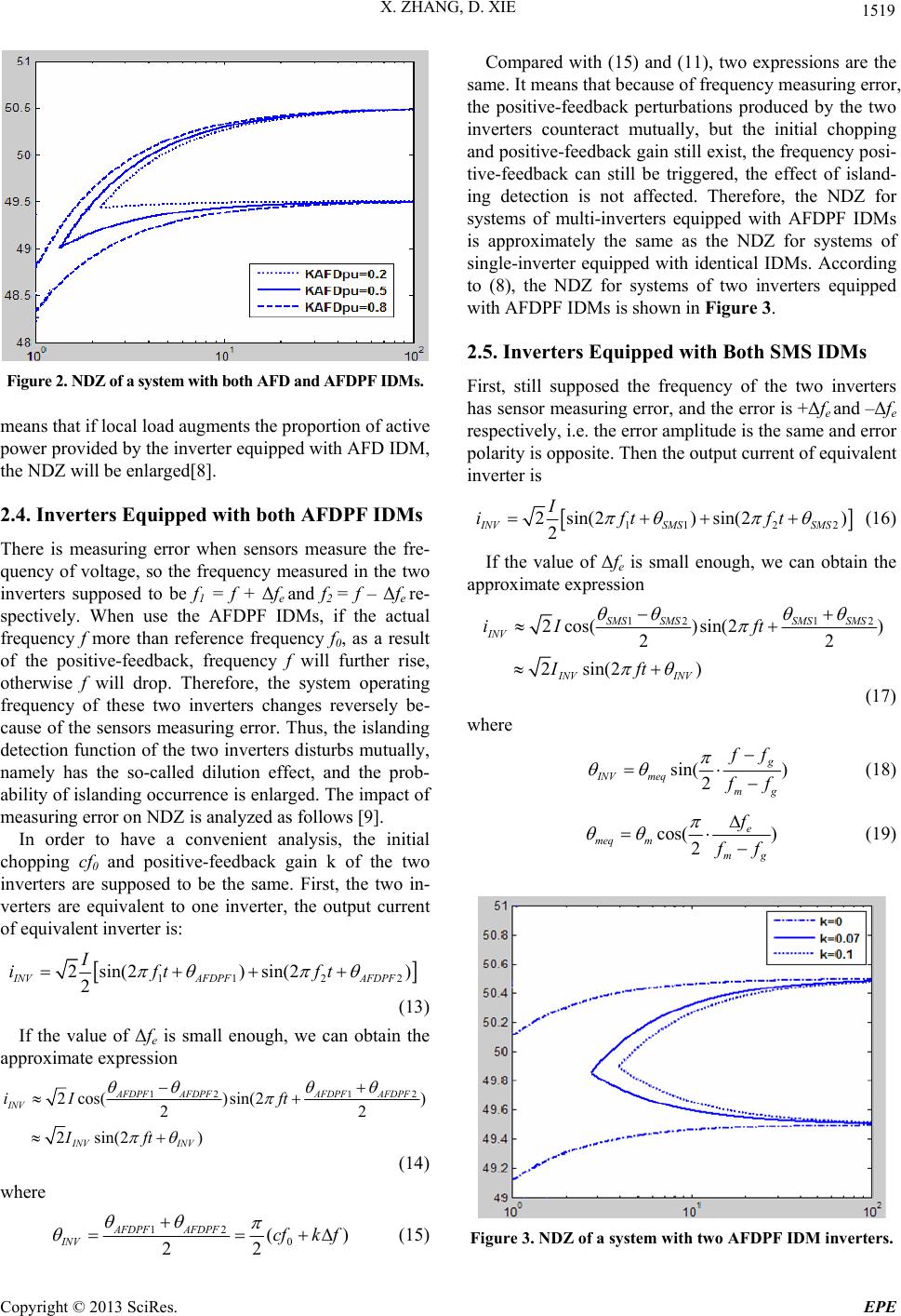
Figure 4. NDZ of a system with two SMS IDM inverters.
The (6) express the current initial phase angle of sin-
gle-inverter system equipped with SMS IDMs. Com-
pared with (19) and (6), we may see that the frequency
measuring error will reduce the amplitude of maximum
phase shifting angle θm, it means that the positive-feed-
back perturbations produced by the two inverters coun-
teract mutually, and the NDZ will increase, so the per-
formance of islanding detection will drop. However,
even if the measuring error Δfe takes a relatively big val-
ue (0.5 Hz), and fmfg =3Hz, the maximum phase shift-
ing angle θmeq drops only 3.4% compared with θm, there
isn’t obvious change for the NDZ. Figure 4 shows the
NDZ for different Δfe (θm = 10°
f
m – fg =3Hz). This
figure indicates that though the frequency measuring
error makes the perturbation produced by the two invert-
ers counteract mutually, it almost has no impact on per-
formance of islanding detection[9].
3. Conclusions
Synthesizing the above analysis, for the islanding de-
tection performance of the multi-inverter grid-connected
PV systems, we may draw the following conclusion:
First, when part of inverters in system adopt active
IDMs, the others use passive IDMs, the application of
passive IDMs enlarges the NDZ, and increases probabil-
ity of islanding; Second, when part of inverters in system
adopt AFD IDMs, the others use positive-feedback
based active IDMs, such as SMS and AFDPF IDMs, the
NDZ will be enlarged and hence increase the possibility
of islanding if we magnify the proportion of load active
power provided by inverters equipped with AFD IDM;
Third, when all the inverters in system adopt AFDPF
IDMs or SMS IDMs, though the sensor measuring error
makes the perturbation produced by the inverters coun-
teract mutually, it almost has no impact on islanding de-
tection performance even if in the worst situation(The
inverters have identical error amplitude and opposite
error polarity).
REFERENCES
[1] K. Agbossou, M. Kolhe, J. Hamelin and T. K. Bose,
“Performance of a Stand-Alone Renewable Energy Sys-
tem Based on Energy Storage as Hydrogen,” IEEE
Transactions on Energy Conversion, Vol.19, No. 3, 2004,
pp. 633-640. doi.org/10.1109/TEC.2004.827719
[2] IEEE Std.929-2000, “IEEE Recommended Practice for
Utility Interface of Photovoltaic (PV) System,” IEEE
Std.929-2000, Apr.2000.
[3] Z. Ye, A. Kowalkar, Y. Zhang, P. Du and R. Walling,
“Evaluation of Anti-islanding Schemes based on non De-
tection Zone Concept,” IEEE Trans on Power Electron,
Vol. 19, No. 5, 2004, pp. 1171-1176.
doi.org/10.1109/TPEL.2004.833436
[4] S. J. Huang and F. S. Pai, “Design and Operation of
Grid-connected Photovoltaic System with Power-factor
Control and Active Islanding Detection,” IEEE Proceed-
ings on Generation, Transmission and distribution, Vol.
148, No. 2, 2001, pp. 243-250.
[5] A. Cardenas, Agbossou and M. L. Doumbia, “An Active
Anti-Islanding Algorithm for Inverter Based Mul-
ti-Source DER Systems,” IEEE Asia-Pacific Power and
Energy Engineering Conference, APPEEC 2009, 27-31
March, 2009, pp. 1-6.
[6] F. R. Liu, Y. Kang and S. X. Duan, “Analysis and Opti-
mization of Active Frequency Drift Islanding Detection
Method,” in Twenty Second Annual IEEE Applied Power
Electronics Confer., APEC 2007, pp. 379-1384.
[7] L. A. C. Lopes and H. Sun, “Performance Assessment of
Active Frequency Drifting Islanding Detection Methods,”
IEEE Transactions on energy Conversion, Vol. 21, No. 1,
2006, pp. 171-180. doi:10.1109/TEC.2005.859981
[8] M. L. Doumbia, K. Agbossou and D. Tran-Khanh-Viet,
“Correlation Technique Investigation for Islanding Detec-
tion of Inverter based Distributed Generation,” in IEEE
Power Electronics Specialists Conference-PESC2008,
2008, pp. 4556-4561.
[9] A. Cardenas, K. Agbossou and M. L. Doumbia, “Island-
ing Detection Method for Multi-Inverter Distributed
Generation,” Journal of Electromagnetic Analysis and
Applications, Vol. 1 No. 3, 2009, pp. 170-180.
doi:10.4236/jemaa.2009.13026