Energy and Power Engineering, 2013, 5, 1153-1158
doi:10.4236/epe.2013.54B219 Published Online July 2013 (http://www.scirp.org/journal/epe)
Safety Distance Determination for 500 kV AC
Transmission Line’s Helicopter Inspection
Shuwei Wan, Xingming Bian, Lan Chen, Liming Wang, Zhicheng Guan
Graduate School at Shenzhen, Tsinghua University, Beijing, China
Email: wansw07@foxmail.com
Received February, 2013
ABSTRACT
As an efficient and advanced line inspection method, helicopter line patrol is gradually more and more used in trans-
mission lines inspection, promoting the elaborate operation of transmission lines and reducing the management cost.
However, as a 'floating-potential conductor' near to a high-voltage transmission line, the helicopter would be at a high
electric field region; and bring security risk to equipment and operating personnel. In this paper, the electric field
strength near the cabin at locations of different distance from transmission lines is investigated by calculation, and the
field in the helicopter cabin is also calculated with finite element method (FEM). The result indicates that the potential
difference becomes higher with the decrease of the distance between the helicopter and transmission line. Considering
the discharge energy and the guarantee of the persons’ safety, the safety distance is determined as d15 m.
Keywords: Transmission Lines; Electric Field; Helicopter Inspection; Safety Distance; Limit-value; Transient Electric
Shock
1. Introduction
Power transmission lines are a key part of the power sys-
tem and are exposed all the year round to the prevailing
weather conditions. It follows that th ey are more prone to
faults than other parts of the system. As an efficient and
advanced line inspection method, helicopter line patrol is
used in inspection of transmission line gradually, pro-
moting the elaborate operation and management. Heli-
copter has the ability to ascend and descend vertically
and to hover motionless at any height, making them ide-
ally suited for monitoring overhead transmission lines
[1-5]. Helicopter enables close observation of the con-
ductors, insulators, fittings and towers, while with infra-
red and UV inspection systems, operators can clearly see
where corona and other discharges are occurring [6-10].
However, when a helicopter is close to a transmission
line, it will, as an isolated conductor, cau se a distortion of
the electric field distribution. This will be particularly
important around those parts of the helicopter having a
small radius of curvature where the field will be high,
perhaps causing localized discharges and the possibility
of a breakdown between line, helicopter and ground,
with the consequent dangers to helicopter, personnel and
equipment.
Calculations concerning floating conductors have been
considered by several investigators [11-16]: Tadashi used
a charge simulation method to determine the field near a
floating conductor touching two dielectric media [11];
Lucian employed a boundary-element method to deter-
mine the field in the region between a charged body and
a conducting disc at a floating potential [12]. Yu dis-
cussed the effects of a floating-potential conductor, near
to a transmission line; the electric field was studied both
by experiment and finite-element computation. An iso-
lated metal sphere and a model of a helicopter were used
as the floating-potential conductors and were placed near
the overhead transmission line [13].
Several authors have considered the fields near or be-
low 3-phase and DC transmission lines with reference to
sag and ground characteristics. Many researchers used
2D-model to calculate the field distribution near trans-
mission lines [17-19], i.e. sag, span and pylons are ne-
glected. The error of result is large. Trlep analyzed a case
more realistic than the ideal case that assumes a flat sur-
face under transmission lines. The result reveals a strong
impact of the configuration of the ground surface and the
presence of conducting bodies under transmission lines
on the electric field distribution [18]. Some researchers
used 3D-model to analyze it [20-23]. Dein took the in-
fluence of tower height, sag, span and the angle of two
spans into consideration [20], calculating the earth’s sur-
face field distribution below 500 kV transmission lines.
The maximum field strength is about 10 kV/m, and the
main component is perpendicular to the surface. Hameyer
used semi-numerical method and finite-element method
Copyright © 2013 SciRes. EPE
S. W. WAN ET AL.
1154
(FEM) to calculate the field. The result of 157 kV trans-
mission lines shows that the maximum field strength (1m
above the ground level) is about 0.5 kV/m [21]. Zhang
discussed the effect of altitude height to 500kV-HVDC
with calculation and analog experiment. Under the same
conditions, the surface field under DC transmission lines
increases as the altitude height rises, and the rising rate is
2~4 kV/m per 1km [22]. Amiri used fi ni t e -element method
(FEM) and charge simulation method (CSM) to discuss
the effect of sag on field distribution under 500 kV
transmission lines. The maximum surface field strength
is about 8.5 kV/m at mid-span while it is about 5 kV/m
near the pylon [23].
At present, the safety distance of 500 kV transmission
lines helicopter line patrol is mainly estimated by ex-
perience. It is twice the length of helicopter wing plus
power operations safety distance. According to the esti-
mation, the distance from helicopter to lines – both hori-
zontal direction and vertical direction – should be over
20 m [24], and it should be over 25 m while helicopter is
hovering motionlessly near pylon [25].
As the helicopter flies close to power line, transient
electric shock phenomena might occur, resulting in the
uncomfortable feeling generated by the persons in the
helicopter. Therefore, the clarification of transient elec-
tric shock is of obvious significance to power corporation,
and also it has been gradually becoming an interesting
object of research work by both physicists and electrical
engineers [26-28]. However, most of the early research-
ers carried out the investigation about transient electric
field on the ground or underwater, none of them noticed
or studied such phenomenon in the helicopter. The effect
of small helicopter model on the electric field near over-
head transmission lines was studied in our previous work
[13].
Many researchers have considered the field distribu-
tion near or below transmission lines, but none appear to
have considered the field distortion due to helicopter near
the transmission lines. In this paper the effect on the
electric field around helicopter n ear to transmission lines
is considered by numerical calculation. The transient
electric shock was analyzed, and then, the safety distance
of helicopter inspection was suggested.
2. Numerical Calculation
The main material of pylon is angle iron. Because the
ratio of maximum and minimum component size is large;
it is hard to finite-element meshing. Taking the network
structure of pylon into account (Figure 1(a)), and ignor-
ing the inner field distribution, th e pylon is modeled as a
solid tower in the model used for the computation, as
shown in Figure 1(b).
The 3D electric field calculation model and the dimen-
sions of BELL206 helicopter are present in Figures 2(a)
and (b). There are two persons in the cabin while inspec-
tion, which is shown in Figure 2(c). The sectional plane
of the model in the helicopter cabin is shown in Figure
2(d). As shown in Figure 2(c), it is clear that the cabin is
not a pure Faraday cage because of the windows; there-
fore the electric field will certainly exist in the cabin. The
line’s voltage is symmetrical three-phase and the line-
to-line voltage is 500 kV (Effective value).
3. Results for Field Calculation and
Experiment
As the mid-span of transmission lines is the closest part
to the ground, the field strength is larger than other plac-
es. The electric field at mid-span along the horizontal
line or 4-line (As shown in Figure 3) normal to the
bundled conductor and linking the conductor and the
helicopter was calculated and measured.
(a) The parameter of 500 kV pylon
(b) FEM computing model
Figure 1. 500 kV pylon.
Copyright © 2013 SciRes. EPE
S. W. WAN ET AL. 1155
(a) 3D Calculation model
(b) The dimensions of helicopter BELL206
(c) Diagram While Inspecting (Did not take off)
(d) Diagram of Calculation Model in Cabin
Figure 2. Calculation Model.
The calculated and measured results are as shown in
Figure 4 for horizon tal line an d 4-line, the agreement
is good.
Consideration of Figure 4 shows that the calculated
field values are consistently higher than the experimental
ones by some 15%. The greater discrepancies are perhaps
because any small positioning errors of the helicopter
and meter up or down, or sideways, or away from the
transmission lines, especially the positioning errors of
helicopter, will cause a decrease in the measured field.
Possibly the effect of the finite size of the metal parts of
the electric field meter itself may lower the reading in a
non-linear and rapidly-changing field.
Figure 3. The diagram of helicopter at different location
from transmission lines.
048 121620
0
10
20
30
40
50
Cabin-surface field (kV/m)
Distance from helicopterto the nearest transmission line(m)
(a) Cabin-surface field while helicopter is at different location along
horizontal line at mid-span
048121620
0
10
20
30
40
50
Cabi n-su rfac e fiel d ( kV/ m )
Distance from helicopterto the nearest transmission line(m)
(b) Cabin-surface field while helicopter is at different location along
45°-line at mid-span
Figure 4. The cabin-surface electric field of helicopter at
mid-span.
Through the result in Figure 4, the filed near helicop-
ter is small and the persons is safe, while the distance
from helicopter to line is over 10 m.
Copyright © 2013 SciRes. EPE
S. W. WAN ET AL.
1156
4. Analysis for Transient Electric Shock
When the distance between the helicopter and transmis-
sion line (d) is in the range 4m to 20 m, the potential and
electric field around the helicopter cabin is calculated by
finite element method, the results (d=4 m, 10m and 20m)
are present in Figure 5. Case d=10 m is taken as an ex-
ample to explain the results.
As shown in Figure 5(a), the potential at middle cab in
changes slightly. The electric field near the cabin win-
dow is not shielded by the helicopter airframe, but de-
creases very fast at the middle cabin. The persons’ poten-
tial (U2, U3) induced is 103.53 kV and 103.11 kV respec-
tively. The maximum potential difference between the
person and helicopter is 1.4 kV (U12).
The case of the helicopter at different positions is also
calculated and the results are displayed in Figure 6.
Transient electric shock is mainly determined by the
discharge energy between two objects, which largely
depends on the capacitance of the objects and the poten-
tial difference between them. It is 50~400 pF while the
person is standing and 400~800 pF while the person is
sitting [29]. The capacitance between the helicopter and
person (sitting) was tested for at least 50 times, and it
-2-10123
60
80
100
120
140
160
139.85
d=20m
d=10m
104.93
69.0 1
70.78
135.31
Persons
102.12
d=4m
Potential (kV)
Distance From Center of Helicopter (m)
Cabi n
(a) Potential distribution along the calculation path
-2-10123
0
5
10
15
20
25
4.94
7.45
11.63
5.40
8.83
d=10m
14.92
d=20m
d=4m
Persons
Electric Field (kV/m)
Distance From Center of Helicopter (m)
Cabin
(b) Electric field distribution along the calcu lation path
Figure 5. Calculation result of d=4 m, 10 m and 20 m.
5101520
0.5
1.0
1.5
2.0
Potential Difference(kV)
Distance From T ransm ission Line to Helicopter(m)
Case d=10m
Figure 6. Potential difference of the helicopter at different
positions.
5 101520
0.0
0.5
1.0
1.5
2.0
Discharge Energy(mJ )
Distance From Tr ansmission Line to Helicopter(m)
Critical distance
Fiugre 7. Discharge energy between personnel and air-
frame.
was in the range 400 pF to 800 pF. In order to ensure the
inspection personnel’s persons safety, the severest condi-
tion is taken into consideration. Therefore, the capaci-
tance between person and helicopter airframe is set as
800 pF, then the discharge energy is acquired (Once the
inspection person touches the helicopter airframe), the
result is present in Figure 7.
While the discharge energy is over 0.5 mJ, the person
would feel uncomfortable [29], so the critical discharge
energy is set as 0.5 mJ. The safety distance could be de-
termined as d15 m through the curve in Figure 7. Ac-
cording to this suggestion, transient electric shock has
not happened to the persons in the helicopter during their
inspection anymore. Consequently, this analysis is of
great significance to the helicopter inspection in power
grid.
5. Conclusions
The surface electric field of helicopter was studied both
by experiment and finite-element computation near to
transmission lines. And the filed near helicopter is small
and the persons is safe, while the distance from helicop-
ter to line is over 15 m. Transient electric shock exits
Copyright © 2013 SciRes. EPE
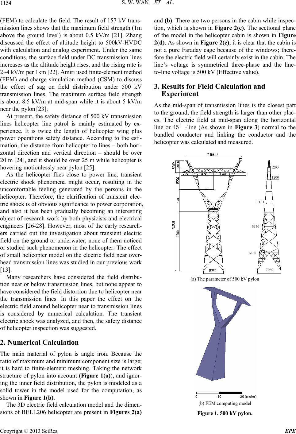
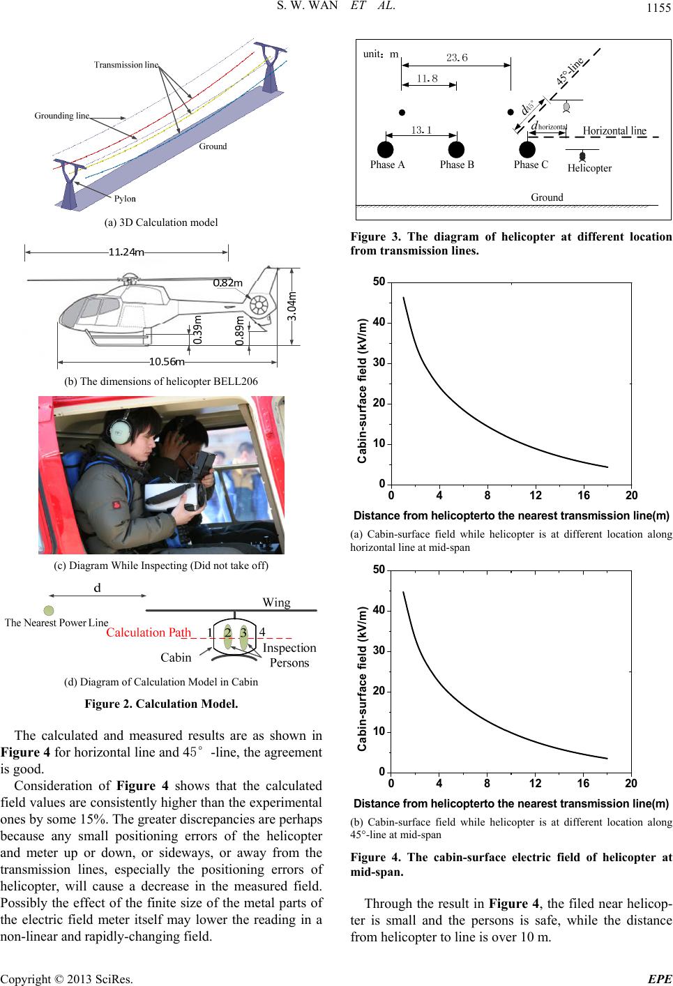
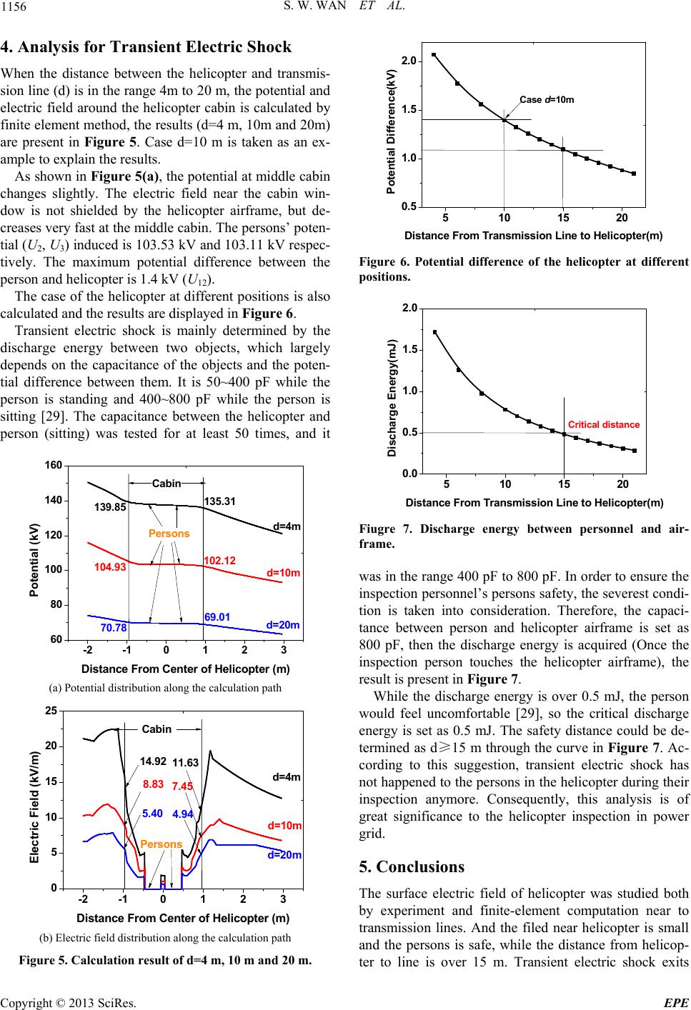
S. W. WAN ET AL. 1157
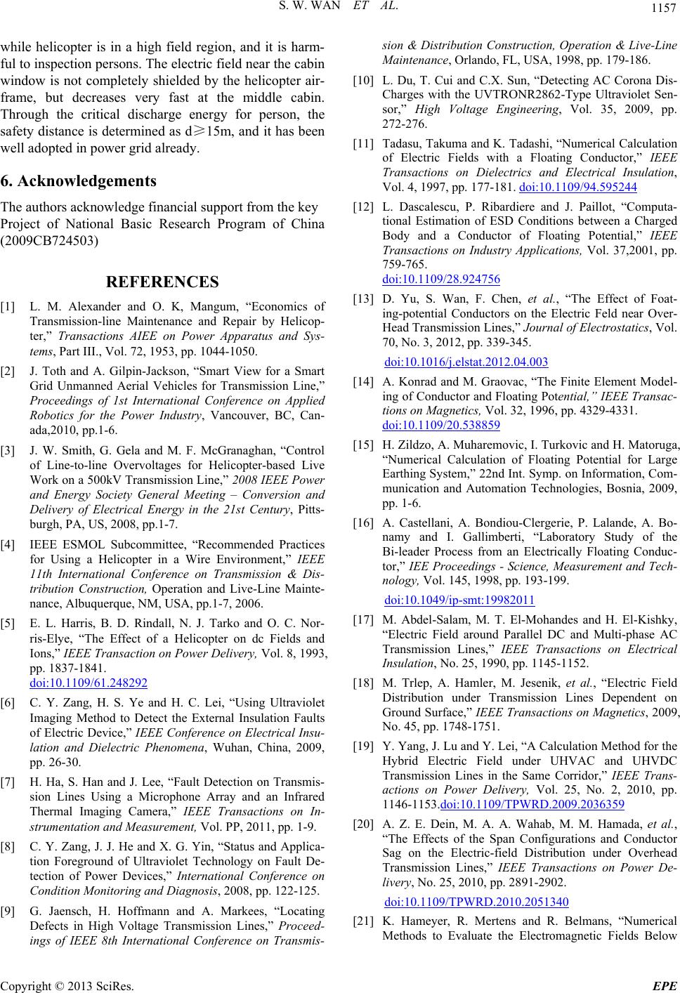
while helicopter is in a high field region, and it is harm-
ful to inspection persons. Th e electric field near the cabin
window is not completely shielded by the helicopter air-
frame, but decreases very fast at the middle cabin.
Through the critical discharge energy for person, the
safety distance is determined as d15m, and it has been
well adopted in power grid already.
6. Acknowledgements
The authors acknowledge financial support from the key
Project of National Basic Research Program of China
(2009CB724503)
REFERENCES
[1] L. M. Alexander and O. K, Mangum, “Economics of
Transmission-line Maintenance and Repair by Helicop-
ter,” Transactions AIEE on Power Apparatus and Sys-
tems, Part III., Vol. 72, 1953, pp. 1044-1050.
[2] J. Toth and A. Gilpin-Jackson, “Smart View for a Smart
Grid Unmanned Aerial Vehicles for Transmission Line,”
Proceedings of 1st International Conference on Applied
Robotics for the Power Industry, Vancouver, BC, Can-
ada,2010, pp.1-6.
[3] J. W. Smith, G. Gela and M. F. McGranaghan, “Control
of Line-to-line Overvoltages for Helicopter-based Live
Work on a 500kV Transmission Line,” 2008 IEEE Power
and Energy Society General Meeting – Conversion and
Delivery of Electrical Energy in the 21st Century, Pitts-
burgh, PA, US, 2008, pp.1-7.
[4] IEEE ESMOL Subcommittee, “Recommended Practices
for Using a Helicopter in a Wire Environment,” IEEE
11th International Conference on Transmission & Dis-
tribution Construction, Operation and Live-Line Mainte-
nance, Albuquerque, NM, USA, pp.1-7, 2006.
[5] E. L. Harris, B. D. Rindall, N. J. Tarko and O. C. Nor-
ris-Elye, “The Effect of a Helicopter on dc Fields and
Ions,” IEEE Transaction on Power Delivery, Vol. 8, 1993,
pp. 1837-1841.
doi:10.1109/61.248292
[6] C. Y. Zang, H. S. Ye and H. C. Lei, “Using Ultraviolet
Imaging Method to Detect the External Insulation Faults
of Electric Device,” IEEE Conference on Electrical Insu-
lation and Dielectric Phenomena, Wuhan, China, 2009,
pp. 26-30.
[7] H. Ha, S. Han and J. Lee, “Fault Detection on Transmis-
sion Lines Using a Microphone Array and an Infrared
Thermal Imaging Camera,” IEEE Transactions on In-
strumentation and Measurement, Vol. PP, 2011, pp. 1-9.
[8] C. Y. Zang, J. J. He and X. G. Yin, “Status and Applica-
tion Foreground of Ultraviolet Technology on Fault De-
tection of Power Devices,” International Conference on
Condition Monitoring and Diagnosis, 2008, pp. 122-125.
[9] G. Jaensch, H. Hoffmann and A. Markees, “Locating
Defects in High Voltage Transmission Lines,” Proceed-
ings of IEEE 8th International Conference on Transmis-
sion & Distribution Construction, Operation & Live-Line
Maintenance, Orlando, FL, USA, 1998, pp. 179-186.
[10] L. Du, T. Cui and C.X. Sun, “Detecting AC Corona Dis-
Charges with the UVTRONR2862-Type Ultraviolet Sen-
sor,” High Voltage Engineering, Vol. 35, 2009, pp.
272-276.
[11] Tadasu, Takuma and K. Tadashi, “Numerical Calculation
of Electric Fields with a Floating Conductor,” IEEE
Transactions on Dielectrics and Electrical Insulation,
Vol. 4, 1997, pp. 177-181. doi:10.1109/94.595244
[12] L. Dascalescu, P. Ribardiere and J. Paillot, “Computa-
tional Estimation of ESD Conditions between a Charged
Body and a Conductor of Floating Potential,” IEEE
Transactions on Industry Applications, Vol. 37,2001, pp.
759-765.
doi:10.1109/28.924756
[13] D. Yu, S. Wan, F. Chen, et al., “The Effect of Foat-
ing-potential Conductors on the Electric Feld near Over-
Head Transmission Lines,” Journal of Electrostatics, Vol.
70, No. 3, 2012, pp. 339-345.
doi:10.1016/j.elstat.2012.04.003
[14] A. Konrad and M. Graovac, “The Finite Element Model-
ing of Conductor and Floating Potential,” IEEE Transac-
tions on Magnetics, Vol. 32, 1996, pp. 4329-4331.
doi:10.1109/20.538859
[15] H. Zildzo, A. Muharemovic, I. Turkovic and H. Matoruga,
“Numerical Calculation of Floating Potential for Large
Earthing System,” 22nd Int. Symp. on Information, Com-
munication and Automation Technologies, Bosnia, 2009,
pp. 1-6.
[16] A. Castellani, A. Bondiou-Clergerie, P. Lalande, A. Bo-
namy and I. Gallimberti, “Laboratory Study of the
Bi-leader Process from an Electrically Floating Conduc-
tor,” IEE Proceedings - Science, Measurement and Tech-
nology, Vol. 145, 1998, pp. 193-199.
doi:10.1049/ip-smt:19982011
[17] M. Abdel-Salam, M. T. El-Mohandes and H. El-Kishky,
“Electric Field around Parallel DC and Multi-phase AC
Transmission Lines,” IEEE Transactions on Electrical
Insulation, No. 25, 1990, pp. 1145-1152.
[18] M. Trlep, A. Hamler, M. Jesenik, et al., “Electric Field
Distribution under Transmission Lines Dependent on
Ground Surface,” IEEE Transactions on Magnetics, 2009,
No. 45, pp. 1748-1751.
[19] Y. Yang, J. Lu and Y. Lei, “A Calculation Method for the
Hybrid Electric Field under UHVAC and UHVDC
Transmission Lines in the Same Corridor,” IEEE Trans-
actions on Power Delivery, Vol. 25, No. 2, 2010, pp.
1146-1153.doi:10.1109/TPWRD.2009.2036359
[20] A. Z. E. Dein, M. A. A. Wahab, M. M. Hamada, et al.,
“The Effects of the Span Configurations and Conductor
Sag on the Electric-field Distribution under Overhead
Transmission Lines,” IEEE Transactions on Power De-
livery, No. 25, 2010, pp. 2891-2902.
doi:10.1109/TPWRD.2010.2051340
[21] K. Hameyer, R. Mertens and R. Belmans, “Numerical
Methods to Evaluate the Electromagnetic Fields Below
Copyright © 2013 SciRes. EPE
S. W. WAN ET AL.
Copyright © 2013 SciRes. EPE
1158
Overhead Transmission Lines and Their Measurement,”
Proceeding of First IEEE International Conference on
Devices, Circuits and Systems, Caracas, Venezuela, 1995,
pp. 32-36.
[22] J. Zhang, G. Zhang, X. Zhang, et al., “Simulation Ex-
periment and Calculation of DC Electric Field Caused by
DC Transmission Line at High Altitude Districts,” High
Voltage Engineering, Vol. 35, No. 8, 2009, pp.
1970-1974.
[23] R. Amiri, H. Hadi and M. Marich, “The Influence of Sag
in the Electric Field Calculation around High Voltage
Overhead Transmission Lines,” IEEE Conference on
Electrical Insulation and Dielectric Phenomena. 2006, pp.
206-209.
[24] T. A. D. C. Society, IEEE Guide for Maintenance Meth-
ods on Energized Power Lines, 2009.
[25] P. Zhao, C. Deng and Y. Yuan, “Patrol of Transmission
Line with Helicopter,” North China Electric Power, No.
10, 2002, pp. 1-3.
[26] J. S. Jung, J. W. Jung and S. Kim, “Transient Phenomena
Analysis of Electric Shock Using ATPDraw,” ICEE
Conference on Progress, July. 2007.
[27] J. D. Tranen and G. L. Wilson, “Electrostatically Induced
Voltages and Currents on Conducting Objects under EHV
Transmission Lines,” IEEE Tranactions on Power Ap-
parently Systems, Vol. pas-90, No. 2, March/April, 1971.
[28] L. R. Delaplace and J. P. Reilly, “Electric and Magnetic
Field Coupling from High Voltage ac Power Transmis-
sion Lines – classification of short – term effects on Peo-
ple,” IEEE Tranactions on Power Apparently Systems,
Vol. pas-97, 1987, pp. 2243-2252.
[29] J. G. Anderson, “Transmission Line Reference Book 345
KV and above,” Electric Research Council and Electric
Power Research Institute, Palo Alto, 1982.