Energy and Power Engineering, 2013, 5, 1097-1100
doi:10.4236/epe.2013.54B209 Published Online July 2013 (http://www.scirp.org/journal/epe)
Effects of DC Magnetic Bias on the Magnetic and Sound
Fields of Transformer
Yan Li, Yanchao gao, Longnv Li, Di Zhang, Fangxu Han
Research Institute of Special Electrical Machines, Shenyang University of Technology, Shenyang, China
Email: gaoyanchao89@126.com
Received March, 2013
ABSTRACT
DC bias current flowing into the neutral point of power transformer will seriously affect the normal operation of AC
power system. In this paper, exciting current, harmonic component of the excitation current, magnetic flux density and
noise of transformer were analyzed when the transformer is in the no-load operation state based on field-circuit coupled
method. Through the calculation and analysis, some reference bases are provided for design of transformer.
Keywords: DC Magnetic Bias; Exciting Current; Harmonic; Magnetic Flux Density; Noise
1. Introduction
As the implementation of the "transmit the electricity
from west to east, north and south to send each other,
nationwide network" strategy of China's power grid,
high-voltage direct current transmission (HVDC) tech-
nology [1-2], which is suitable for high power and long-
distance transmission, has been used more and more
widely. Under unipolar-earth way, the DC into the earth
will be large up to 3 kA [3]. It causes the uneven distri-
bution of surface potential. Thus there is potential dif-
ference between different grounds which makes some of
the DC flows from one transformer end and sides out
from the other end. Field tests show that only a small DC
flows through the transformer neutral point will seriously
harm or even affect the normal operation of alternat-
ing-current power system. Therefore, it is necessary to
pay more attention to the problem of transformer DC
magnetic bias.
Taking a single-phase transformer as an example, on
the basis of field-circuit coupled finite element method,
this paper simulates the DC magnetic bias's impact on
exciting current, exciting current harmonic, magnetic
flux density and noise of transformer when the trans-
former is switched to the zero-loaded state. It will be of a
great significance for the further study of controlling DC
magnetic bias.
2. Model of Transformer under DC
Magnetic Bias
2.1. Finite Element Modeling
A single-phase transformer with a parameter of 240
MVA was chosen as an example. In order to analyze the
DC magnetic bias's impact on transformer, field-circuit
coupled finite element method was used and the finite
element model is shown in Figure 1. The field domain
was shown on the left side of Figure 1, and the circuit
domain was on the right.
2.2. Calculation on Excitation Current
Zero-loaded is an operating state, it refers to disconnect
in the secondary side and rated voltage in the primary
side. The exciting current was consisted of core loss cur-
rent
F
e
I
(active current) and magnetizing current I
(reactive current), which is shown in Figure 2.
0
0
(%) 10
(%) ()
10
o
N
I
F
eFe ff
N
P
IS
K
I
qG NqA
S


(1)
*This work was supported by NSFC, under Project 51177103 and
Pro
g
ram for LNIRT in Universit
y
(
LT2011002
)
. Figure 1. Field-circuit coupled finite element model.
Copyright © 2013 SciRes. EPE
Y. LI ET AL.
1098
Figure 2. Phase diagram of transformer on zero-load.
In formula (1), 0 is the zero-load loss, P
N
S is the
rated capacity.
F
e is the magnetization capacity of unit
mass, q
q
is the magnetization capacity of unit area at
seam crossing,
F
e is the total weight of the core, G
f
A
is the net area at seam crossing and
f
N is the Number
of joints;
2
0(%)(%) (%)
Fe
III

2
(2)
3. Magnetic Field Characteristics under DC
Magnetic Bias
3.1. Exciting Current of Different DC Magnetic
Bias Level
The relation between allowable DC current and rated
current was defined in the reference 4. The allowable DC
current was 0.3% rated current in single-phase trans-
former, 0.5% rated current in three-phase five-limb trans-
former and 0.7% rated current in three-phase three- limb
transformer [4]. The allowable DC current of single-
phase three-limb transformer in this paper is 2.27 A. The
DC current applied in this simulation is 0.6 A1.13 A
2.27 A4.54 A6.81 A9.08 A (0.07%0.15%0.3%
0.6%0.9%1.2% rated current res pecti vel y ). Chan gi n g
rule of exciting current is calculated when different DC
current flows through the winding. Results are shown in
Table 1.
Table 1. Exciting current peak of different dc magnetic bias
level.
DC Current/A Peak of Positive
Half-cycle/A Peak of Negative
Half-cycle/A
0 1.51 -1.51
0.6 7.93 -0.30
1.13 13.1 -0.25
2.27 22.1 -0.16
4.54 27.1 0.11
6.8 32.5 -0.05
9.08 35.2 -0.002
With the increasing of DC current, the exciting curren t
wave get distortion, and the distortion become serious
with the increase of DC current. The peaked wave of the
positive half cycle is more obvious, and the amplitude of
the wave increase. The negative half-cycle is approxi-
mately flat-topped wave, and the amplitude tends to zero.
When the DC current is 9.08 A, the amplitude in positive
half-cycle is 35.1944 A, in negative half-cycle is -0.0025
A. After DC current exceeds 4.54 A, the exciting current
change slowly with the DC current growth. The main
reason is that ferromagnetic material has been highly
saturated. Therefore, changing the magnetic characteris-
tics of ferromagnetic material is a method of inhibiting
DC bias.
3.2. Analysis of Exciting Current
Based on formula 3, exciting current waveform's Fourier
transform is analyzed. Results are shown in Figures 3-4.
01
()sin( )
n
n
itIIn tn
 
(3)
Figure 3. Change curves of exciting currents' harmonic
ratios along with DC current.
Figure 4. Change curves of exciting currents' harmonic
components along with DC current.
Copyright © 2013 SciRes. EPE
Y. LI ET AL. 1099
As shown in Figure 3, with the increasing of DC cur-
rent, the ratio of each exciting current harmonic to fun-
damental exciting current increase rapidly, and the sec-
ond exciting current harmonic is the most obvious. When
the DC current is 2.27A, the increment speed of current
harmonic ratios begin stable.
The corresponding relation between each exciting
current harmonics and DC Bias current is shown in Fig-
ure 4. The DC magnetic bias's impact on each exciting
current harmonics are basically identical, it is approxi-
mately linear relationship. Lower-order harmonic is in-
fluenced by DC Magnetic Bias sensitively, higher-order
harmonic is less affected.
3.3. DC Magnetic Bias's Impact on Flux Density
The calculated position of flux density is shown in Fig-
ure 5. Position A is in the halfway of core window
height. Position B is the centre line of iron beam. Posi-
tion C is in the middle of the two windings.
Transformer operates in inflection point of B-H curv e.
Core model in this paper is 30 RGH120, th e linear region
is 1.7-1.75 T. As shown in figures 6-8, when a curren t in
DC nature in the transformer exists, with the growth of
DC current, the magnetic flux density increases signifi-
cantly. The Maximum flux density on the iron beam is
changed from 1.8347 T to 1.94994 T, on ferrite yoke is
changed from 1.707 T to 1.866T. With the increasing of
DC current, the magnetic flux density increases, but the
amplitude is narrow. Because of the influence of DC
current, ferromagnetic material is easy to get saturated.
The flux density in air way increases significantly. It
changed from 3.664 to 10.84 mT. It is shown that DC
magnetic bias makes leakage magnetic field rise seri-
ously.
4. Acoustical Characteristic of Core under
DC Magnetic Bias
Audible noise is generated due to the vibration of the
transformer. DC bias current flowing through the neu-
trals of ac power transformers with the neutral grounded,
will force the transformer to generate more leak magnetic
flux. Therefore, the core and windings would vibrate
strongly due to the magnetostriction and the electrody-
namics effects. The audible noise level of ac power
transformers neighboring the dc grounding electrode
increase with the increase of the DC current.
In this paper, the characteristics of structural acoustic
radiation are investigated by the indirect boundary ele-
ment method. In order to simulate the ground, symmetry
plane is added in the bottom of transformer core. The
plane is regarded as rigid plane and has no normal accel-
eration, then the noise is reflected entirely. This model
can simulate noise caused by core accurately.
Figure 5. Calculated position of flux density.
Figure 6. Flux density of position A.
Figure 7. Flux density of position B.
Figure 8. Flux density of position C.
Copyright © 2013 SciRes. EPE
Y. LI ET AL.
Copyright © 2013 SciRes. EPE
1100
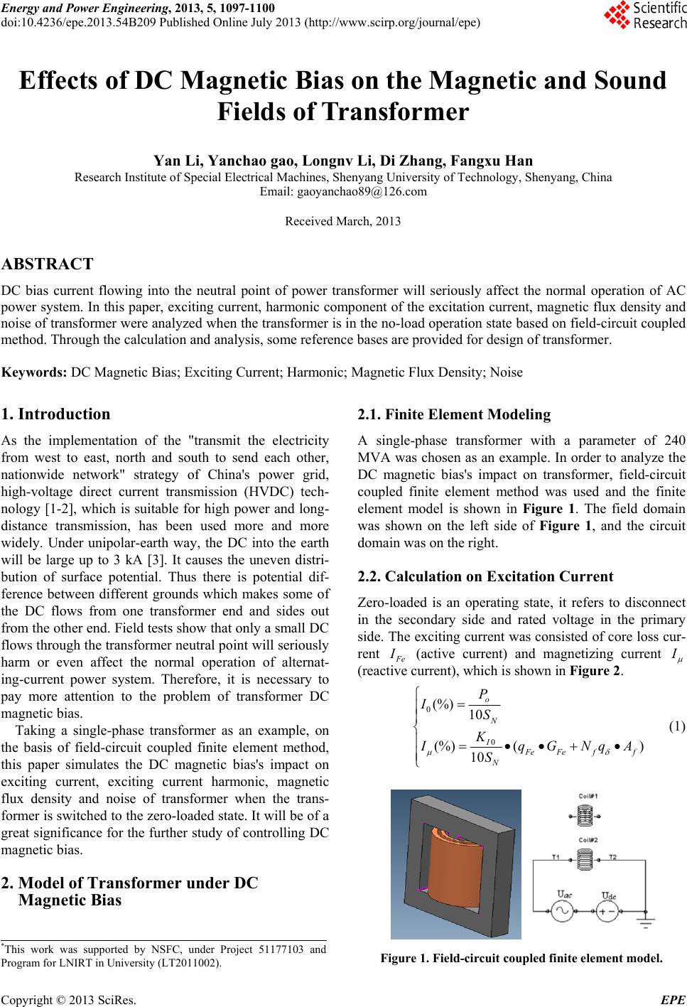
Figure 9. Sound pressure distribution.
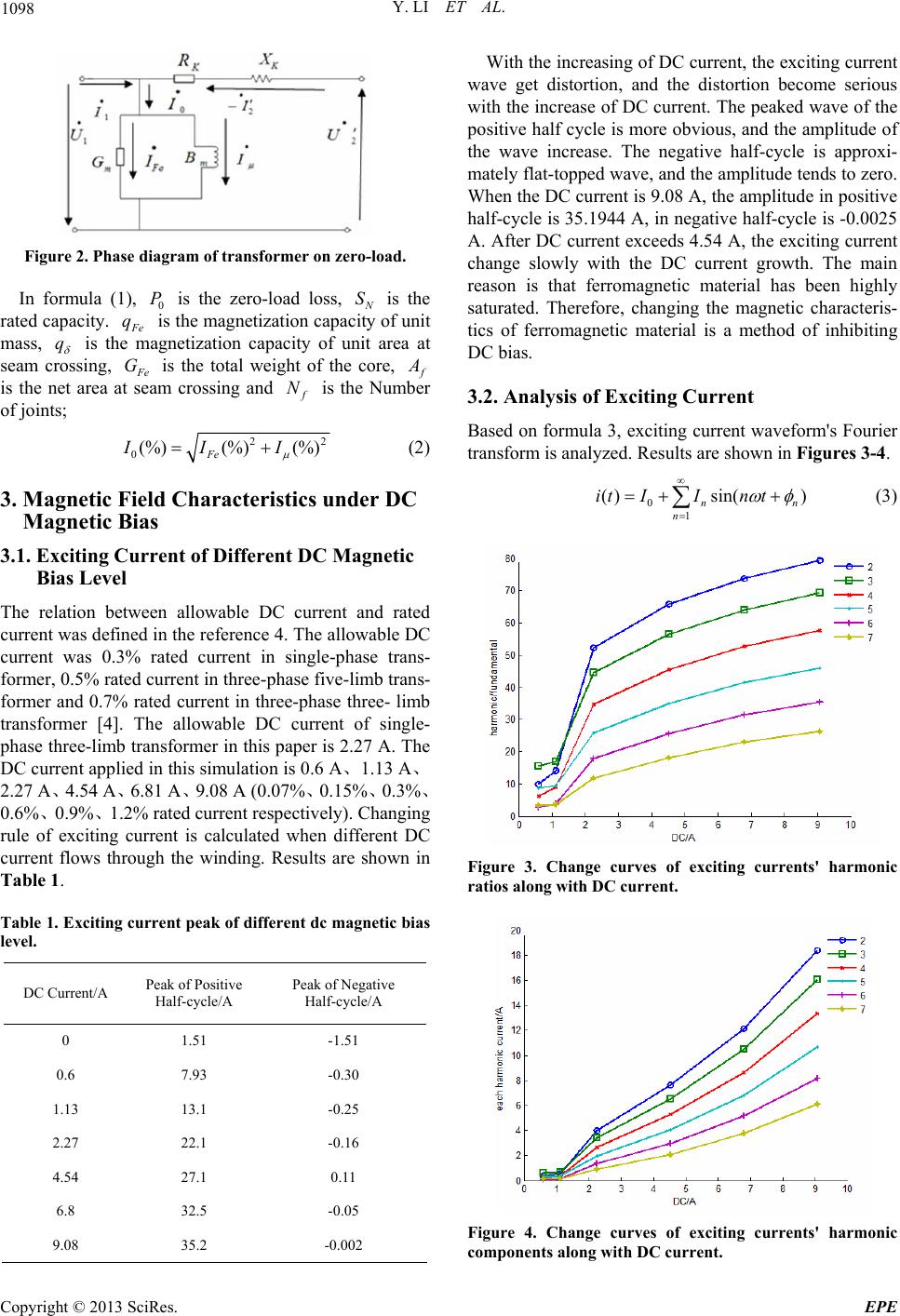
Table 2. Sound pressure level of different dc magnetic bias
level (db)
dc
I/A 100/Hz 200/Hz 300/Hz 400/Hz 500/Hz
0 52.88 76.51 69.3 46.3 60.3
0.6 62.21 86.17 79.7 58.6 69.5
1.13 65.8 85.68 76.3 67.4 69.3
2.27 65.2 86.74 82.2 58.7 67.1
4.54 70.85 94.68 85.4 70.7 78.5
6.8 76.53 99.69 98.2 75.6 67.5
9.08 77.18 100.70 90.7 78.0 82.4
Audible noise is generated due to the vibration of the
transformer. DC bias current flowing through the neu-
trals of ac power transformers with the neutral grounded,
will force the transformer to generate more leak magnetic
flux. Therefore, the core and windings would vibrate
strongly due to the magnetostriction and the electrody-
namics effects. The audible noise level of ac power
transformers neighboring the dc grounding electrode
increase with the increase of the DC current.
In this paper, the characteristics of structural acoustic
radiation are investigated by the indirect boundary ele-
ment method. In order to simulate the ground, symmetry
plane is added in the bottom of transformer core. The
plane is regarded as rigid plane and has no normal accel-
eration, then the noise is reflected entirely. This model
can simulate noise caused by core accurately.
The basic frequency of transformer noise is twice as
high as the source frequency, videlice t 100 Hz. Ther e are
also high frequency noise integer times of basic fre-
quency. Study show that, low-frequency noise is a large
percent in the noise spectrum of frequencies. Therefore,
the noise be l o w 500 Hz wa s taken into account.
As seen in Table 2, noise mainly concentrates in the
frequency of 100200300 Hz. The noise level increases
with the increase of the DC current. The noise level is
76.51 dB when there is no DC current and 100.71 dB
when D C current rise to 9 . 08 A.
5. Conclusions
Based on field-circuit coupled finite element method, this
paper analyzes the DC magnetic bias's impact on ex citin g
current, exciting curren t harmonic, magnetic flux density
and noise of transformer.
1) With the increasing of DC current, the exciting cur-
rent wave get distortion, and the distortion become seri-
ous with the increase of DC current. When the DC cur-
rent is 9.08 A, the amplitude in positive half-cycle is
35.1944 A, in neg ative half-cycle is -0.0025 A. After DC
current exceeds 4.54 A, the exciting current change
slowly with the DC current growth. The main reason is
that ferromagnetic material has been highly saturated.
2) It is approximately linear relationship between each
exciting current harmonics and DC Bias current. Lower-
order harmonic is influenced by DC Magnetic Bias sen-
sitively.
3) With the increase of DC magnetic bias current, the
flux density in air way changed from 3.664 to 10.84 mT,
has increased by 197 percent. It is shown that DC mag-
netic bias makes leakage magnetic field rise seriously.
4) The audible noise level of transformer increase with
the increase of the DC magnetic bias current. When the
DC magnetic bias current change from 0 to 9.08 A, the
amplitude of the sound increase from 76.51 dB to 100.70
dB.
REFERENCES
[1] Y.Y. Zhu, W. P. Jiang and Z. H. Zeng, “Studying on
Measures of Restraining DC Current through Transformer
Neutrals,” Proceedings of the CSEE, Vol. 5, No. 13, 2005,
pp. 300-305.
[2] M. Lahtinen and J. Elovaara. “GIC Occurrences and GIC
test 400kV System Transformer,” IEEE Transaction on
Power Delivery, Vol. 17, No. 2, 2002, pp. 555-561.
doi:10.1109/61.997938
[3] Y. Y. Yao, “Research on the DC Bias Phenomena of
Large Power Transformers,” Shenyang: Shenyang Uni-
versity of Technology, 2000. pp. 415-420.
[4] S. Yuan and T. S. Wang. “Summary of the Research on
Transformer DC Magnetic Bias,” High Voltage Appara-
tus, Vol. 46, No. 3, 2010, pp. 83-87.