Energy and Power Engineering, 2013, 5, 1089-1092
doi:10.4236/epe.2013.54B207 Published Online July 2013 (http://www.scirp.org/journal/epe)
3D Finite Element Analysis of the Stray Loss in Power
Transformer Structure Parts*
Yan Li, Longnv Li, Yongteng Jing, Bo Zhang
Research Institute of Special Electrical Machines, Shenyang University of Technology, Shenyang, China
Email: lilongnv620@163.com
Received March, 2013
ABSTRACT
In order to analyze the leakage magnetic field and stray loss in power transformer, leakage magnetic field and stray loss
in structure parts of a power transformer are calculated by three-dimensional (3-D) non-linear time harmonic finite ele-
ment method (FEM). The results show th at stray loss and loss density in structure parts are large an d which may lead to
local overheating and affect performance of the transformer. The magnetic shields are used to reduce the stray loss and
loss density of power transformer. Effects of these shields on stray loss and loss density of structure parts are discussed.
The results show that stray loss and local overheating can be reduced and eliminated effectively by adding magnetic
shields. It provides some references for the analysis of stray loss and optimization design in transformer.
Keywords: Finite Element Method; Stray Loss; Leakage Magnetic Field; Local Overheating; Magnetic Sh ields
1. Introduction
Power transformer is the core of energy conversion and
transmission in power network, which is also the most
important and expensive equipment. So it will have an
essential impact of power network whether the trans-
former is safe, reliable and economic operation or not [1].
With the increase of capacity of the transformer, the
magnetic leakage field is increasing which may enlarge
the stray loss in the structure parts of power transformer.
In the large power transformer, leakage magnetic field
generated by the winding current will produce losses in
the metal structure parts, and these losses is part of the
transformer load losses, it often tend to local overheating
because of its unevenly distribution. So it is quite neces-
sary to study the magnetic leakage and stray loss deeply
and accurately [2,3].
In this paper, a practical power transformer model of
type SZ10-5000 0kVA/110k V was app lied to research the
stray loss problem in large power transformer by using
3-D nonlinear time harmonic analysis. Detailed calcula-
tion and analysis was proceeded in order to determine the
concentration of stray loss in transformer structure parts,
and magnetic shields were used to reduce stray loss and
prevent local overheating.
2. 3D Calculation Model and Calculation
Method
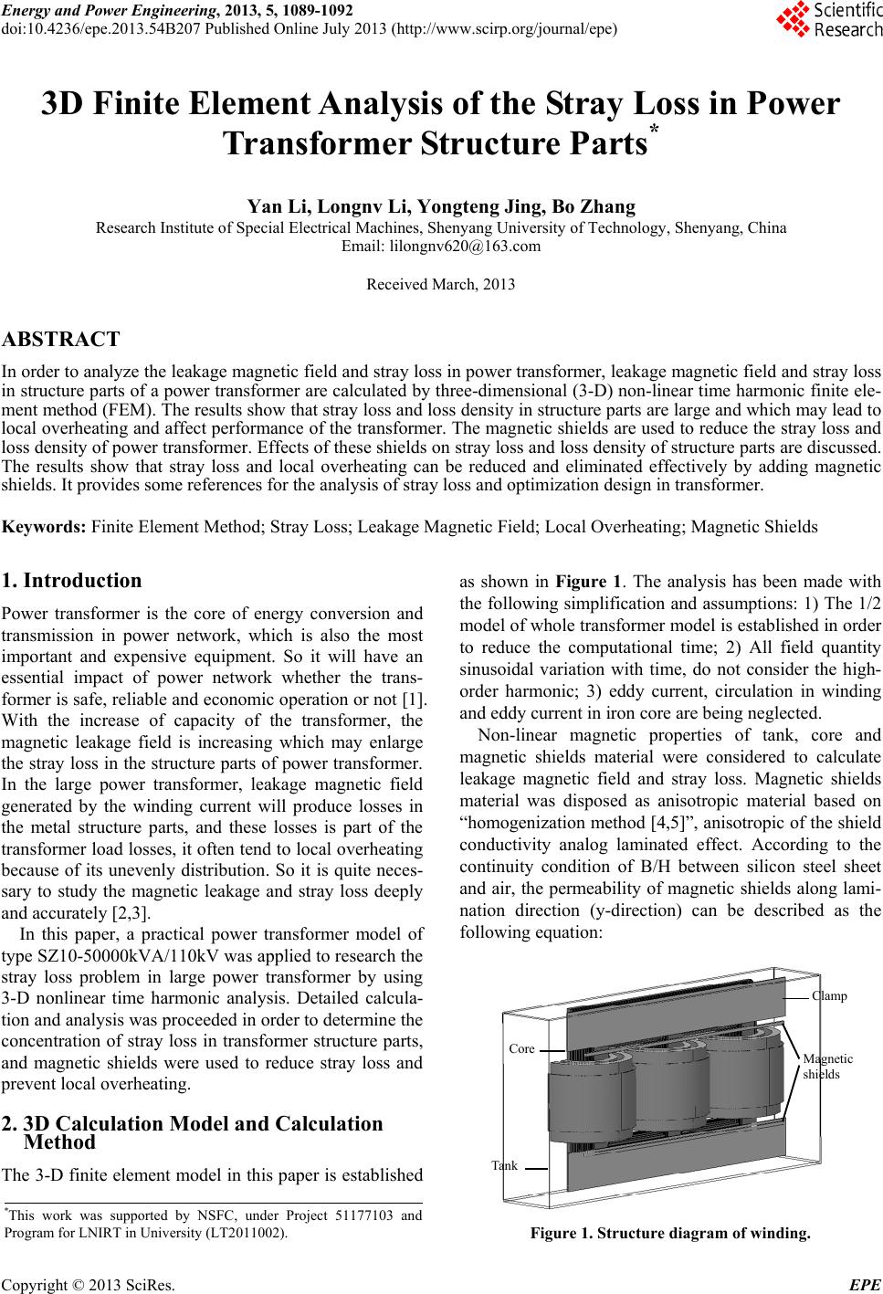
The 3-D finite element model in this paper is established
as shown in Figure 1. The analysis has been made with
the following simplification and assumptions: 1) The 1/2
model of whole transformer model is established in order
to reduce the computational time; 2) All field quantity
sinusoidal variation with time, do not consider the high-
order harmonic; 3) eddy current, circulation in winding
and eddy current in iron core are being neglected.
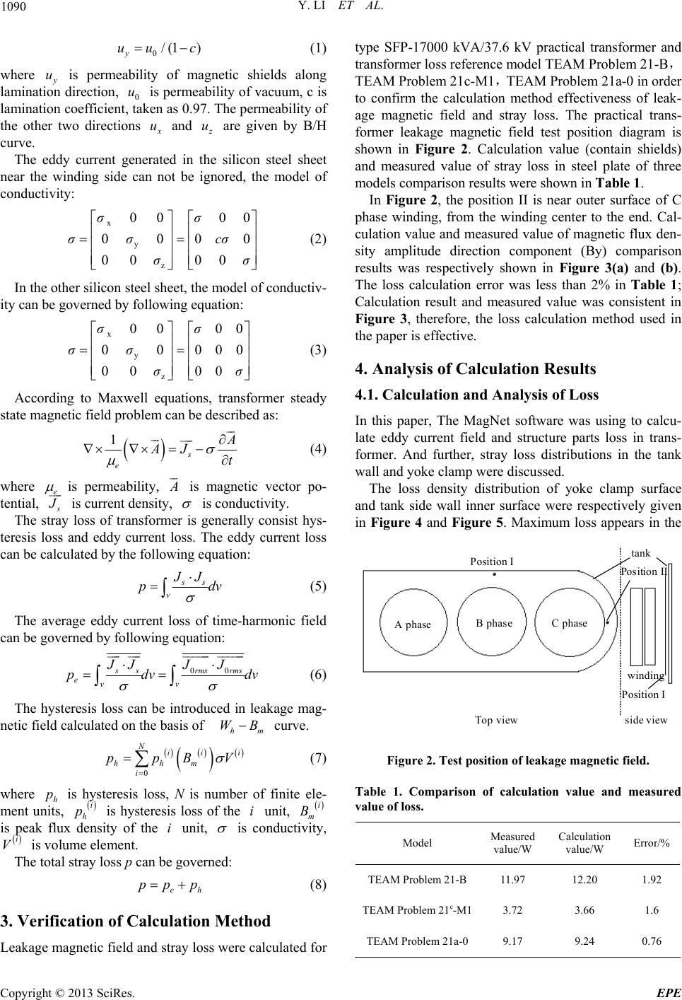
Non-linear magnetic properties of tank, core and
magnetic shields material were considered to calculate
leakage magnetic field and stray loss. Magnetic shields
material was disposed as anisotropic material based on
“homogenization method [4,5]”, anisotropic of the shield
conductivity analog laminated effect. According to the
continuity condition of B/H between silicon steel sheet
and air, the permeability of magnetic shields along lami-
nation direction (y-direction) can be described as the
following equation:
Core
Tank
Clamp
Magnetic
shields
*This work was supported by NSFC, under Project 51177103 and
Program for LNIRT in University (LT2011002). Figure 1. Structure diagram of winding.
Copyright © 2013 SciRes. EPE
Y. LI ET AL.
1090
0/(1 )
y
uu c
(1)
where
y
u is permeability of magnetic shields along
lamination direction, 0 is permeability of vacuum, c is
lamination coefficient, taken as 0.97. The permeability of
the other two directions
u
x
u and
z
u are given by B/H
curve.
The eddy current generated in the silicon steel sheet
near the winding side can not be ignored, the model of
conductivity:
x
y
z
00 00
000
00 00
σσ
σσ cσ
σσ






0
0
(2)
In the other silicon steel sheet, the model of conductiv-
ity can be governed by following equation:
x
y
z
00 00
0000
00 00
σσ
σσ
σσ






(3)
According to Maxwell equations, transformer steady
state magnetic field problem can be described as:

1
s
e
A
AJ t



 (4)
where e
is permeability,
A
is magnetic vector po-
tential,
s
J
 is current density,
is conductivity.
The stray loss of transformer is generally consist hys-
teresis loss and eddy current loss. The eddy current loss
can be calculated by the following equation:
ss
v
JJ
p
d
v
(5)
The average eddy current loss of time-harmonic field
can be governed by following equatio n:
00ssrmsrms
evv
JJJ J
pdv




 
dv
m
(6)
The hysteresis loss can be introduced in leakage mag-
netic field calculated on the basis of curve.
h
WB
 

0
Nii
hhm
i
ppBV
i
(7)
where h is hysteresis loss, N is number of finite ele-
ment units, is hysteresis loss of the unit,
is peak flux density of the unit,
p

i
h
p i

i
m
B
i
is conductivity,
is volume element.

i
VThe total stray loss p can be governed:
e
pp p
h
(8)
3. Verification of Calculation Method
Leakage magnetic field and stray loss were calculated for
type SFP-17000 kVA/37.6 kV practical transformer and
transformer loss reference model TEAM Problem 21-B
TEAM Problem 21c-M1TEAM Problem 21a-0 in order
to confirm the calculation method effectiveness of leak-
age magnetic field and stray loss. The practical trans-
former leakage magnetic field test position diagram is
shown in Figure 2. Calculation value (contain shields)
and measured value of stray loss in steel plate of three
models comparison results were shown in Table 1.
In Figure 2, the position II is near outer surface of C
phase winding, from the winding center to the end. Cal-
culation value and measured value of magnetic flux den-
sity amplitude direction component (By) comparison
results was respectively shown in Figure 3(a) and (b).
The loss calculation error was less than 2% in Table 1;
Calculation result and measured value was consistent in
Figure 3, therefore, the loss calculation method used in
the paper is effective.
4. Analysis of Calculation Results
4.1. Calculation and Analysis of Loss
In this paper, The MagNet software was using to calcu-
late eddy current field and structure parts loss in trans-
former. And further, stray loss distributions in the tank
wall and yoke clamp were discussed.
The loss density distribution of yoke clamp surface
and tank side wall inner surface were respectively given
in Figure 4 and Figure 5. Maximum loss appears in the
Posit i on I
Top view side view
tank
Position I
winding
A phaseB phaseC pha s e
Po si ti o n II
Figure 2. Test position of leakage magnetic field.
Table 1. Comparison of calculation value and measured
value of loss.
Model Measured
value/W Calculation
value/W Error/%
TEAM Problem 21-B 11.97 12.20 1.92
TEAM Problem 21c-M13.72 3.66 1.6
TEAM Problem 21a-09.17 9.24 0.76
Copyright © 2013 SciRes. EPE
Y. LI ET AL. 1091
200
150
100
50
0
0
350
700
1050
The axial height/mm
B
y
/10-4T
Measured
value
Calculation
value
(a) Position I
500
400
300
200
100
0 0 100 200 300 400
Measured
value
Calculati o
n
value
The axial height/mm
By/10
-4
T
(b) Position II
Figure 3. Comparison of calculation value and measured
value of magnetic flux density at assigned position.
H(mm)
Loss density(W/m
3
)
L(mm)
Figure 4. Diagram of loss density distribution on surface of
yoke clamp.
H(mm)
Loss den sity(W/m
3
)
L(mm)
Figure 5. Diagram of loss density distribution on inner sur-
face of tank side wall.
corresponding position of A and C phase end winding,
and the maximum loss density appears in the lower
clamp; the loss in transformer tank was mainly concen-
trated in the tank side wall near C phase and tank wall
corresponding to the middle of the three-phase windings.
The H and L in diagram were respectively expressed the
length and height of the tank (or clamp). The length of
the tank side wall and clamp were 790mm and 3760mm,
and the heights were 2730mm and 535mm. The stray
loss and loss density of transformer tank and clamp were
shown in Table 2.
4.2. Calculation and Analysis of Loss by Adding
Magnetic Shields
The stray loss uneven distribution of transformer structure
parts can cause local overheating and affect the normal
performance of transformer, through adding magnetic
shields can reduce the stray loss.
Magnetic shields material with high permeability at-
tract the leakage magnetic field into the magnetic shields,
prevent leakage magnetic into tank and other structure
parts, thereby reduce the stray loss in the structure parts
of transformer. Transformer adding magnetic shields is
shown in Figure 1. Loss density of tank and clamp add-
ing shields was decline in Figure 6 and Figure 7, maxi-
mum loss still appear near clamp and tank side wall,
maximum loss density of clamp decreased by 43.1%
compared to non-magnetic shields, maximum loss den-
sity of tank decreased by 11.1%. The maximum stray
loss and loss density of transformer structure parts with
magnetic shields as shown in Table 3.
Table 2. Loss and Loss Density of Transformer Structure
Parts.
Component Tank Clamp
Loss density(W/m3) 1.8106 1.6
107
Eddy current loss(W) 9846.76 4720.4
Hysteresis loss (W) 3603.79 942.68
Total loss(W) 13 450.55 5663.08
Loss density(W/m
3
)
L(mm) H(mm)
Figure 6. Diagram of loss density distribution on surface of
yoke clamp with magnetic shields.
Copyright © 2013 SciRes. EPE
Y. LI ET AL.
Copyright © 2013 SciRes. EPE
1092
H(mm)
Loss den si ty(W/m
3
)
L(mm)
H
(
mm
)
L(mm)
B
(
T
)
Figure 7. Diagram of loss density distribution on inner sur-
face of tank side wall with magnetic shields. Figure 9. Diagram of magnetic flux density distribution on
surface of yoke clamp without magnetic shields.
Table 3. Loss and Loss Density of Transformer
Structure Parts with Magnetic Shield.
ComponentTankCla mp
Loss density(W/m3)1.6
106 9.1
106
Eddy current loss (W)5708.37 2313.94
Hysteresis loss (W)2626.9 579.46
Total loss (W)8335.27 2893.4
1) The results get by 3D finite element analysis are
consistent with theoretical analysis, illustrate the validity
of the method.
2) Loss and the loss density in the local place of trans-
former structure parts can be reduced effectively by add-
ing magnetic shield. After adding magnetic shield to tank
and yoke clamp, the maximum stray loss and loss density
of tank are reduced by 38% and 11.1%, the maximum
stray loss and loss density of clamp are reduced by
48.9% and 43.1%.
4.3. Magnetic Shields Effect on Structure Parts
of Leakage Magnetic Field 3) The density of magnetic flux leakage into the clamp
is decreased obviously after adding magnetic shields.
The magnetic flux densities of clamp surface with and
without magnetic shields were shown in Figure 8 and
Figure 9. Magnetic shields provide a conduction path for
leakage magnetic of transformer interface winding. It can
be seen from the Figure, leakage magnetic flux density
significantly lower by adding magnetic shields.
REFERENCES
[1] M. Rizzo, A. Savini and J. Turowski, “Influence of Flux
Collectors on Stray Losses in Transformers,” IEEE
Transactions on Magnetics, Vol. 36, No. 4, 2000, pp.
1915-1918. doi:10.1109/20.877821
5. Conclusions [2] A. S. Reddy and M. Vijaykumar, “Hot Spot and Life
Evaluation of Power Transformer Design Using Finite
Element Method,” Journal of Theoretical and Applied
Information Technology, Vol. 4, No. 3, 2008, pp.
238-243.
In this paper, 3D finite element method is used to calcu-
late the stray loss of transformer structure parts, and the
conclusions are as follows: [3] N. Takahashi, T. Sakura and Z. Cheng, “Nonlinear
Analysis of Eddy Current and Hysteresis Losses of 3-D
Stray Field Loss Model Problem 21,” IEEE Transactions
on Magnetics, Vol. 37, No. 5, 2011, pp. 3672-3675.
doi:10.1109/20.952687
H
(
mm
)
L(mm)
B
(
T
)
[4] K. Laurent, D. Patrick and Z. Tarek, “Homogenization of
Lamination Stacks in Linear Magneto Dynamics,” IEEE
Transactions on Magnetics, Vol. 40, No. 2, 2004, pp.
912-915. doi:10.1109/TMAG.2004.825435
[5] K. Hiroyuki, K. Akihisa and F. Koji, “FEM Computation
of Magnetic Field and Iron Loss in Laminated Iron Core
Using Homogenization Nethod,” IEEE Transactions on
Magnetics, Vol. 43, No. 4, 2007, pp. 1405-1408.
doi:10.1109/TMAG.2007.892429
Figure 8. Diagram of magnetic flux density distribution on
urface of yoke clamp with magnetic shields.
s