Paper Menu >>
Journal Menu >>
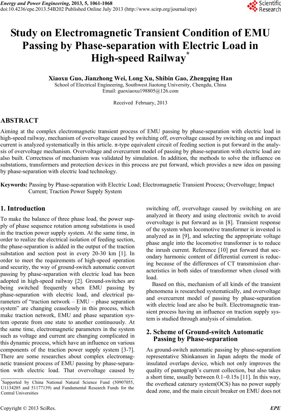 Energy and Power Engineering, 2013, 5, 1061-1068 doi:10.4236/epe.2013.54B202 Published Online July 2013 (http://www.scirp.org/journal/epe) Study on Electromagnetic Transient Condition of EMU Passing by Phase-separation with Electric Load in High-speed Railway* Xiaoxu Guo, Jianzhong Wei, Long Xu, Shibin Gao, Zhengqing Han School of Electrical Engineering, Southwest Jiaotong University, Chengdu, China Email: guoxiaoxu198805@126.com Received February, 2013 ABSTRACT Aiming at the complex electromagnetic transient process of EMU passing by phase-separation with electric load in high-speed railway, mechanism of overvoltage caused by switching off, overvoltage caused by switching on and impact current is analyzed systematically in this article. π-type equivalent circuit of feeding section is put forward in the analy- sis of overvoltage mechanism. Overvoltage and overcurrent model of passing by phase-separation with electric load are also built. Correctness of mechanism was validated by simulation. In addition, the methods to solve the influence on substations, transformers and protection devices in this process are put forward, which provides a new idea on passing by phase-separation with electric load technology. Keywords: Passing by Phase-separation with Electric Load; Electromagnetic Transient Process; Overvoltage; Impact Current; Traction Power Supply System 1. Introduction To make the balance of three phase load, the power sup- ply of phase sequence rotation among substations is used in the traction power supply system. At the same time, in order to realize the electrical isolation of feeding section, the phase-separation is added in the output of the traction substation and section post in every 20-30 km [1]. In order to meet the requirements of high-speed operation and security, the way of ground-switch automatic convert passing by phase-separation with electric load has been adopted in high-speed railway [2]. Ground-switches are being switched frequently when EMU passing by phase-separation with electric load, and electrical pa- rameters of “traction network – EMU – phase separation system” are changing ceaselessly in this process, which make traction network, EMU and phase separation sys- tem operate from one state to another continuously. At the same time, electromagnetic parameters in the system such as voltage and current are changing complicated in this dynamic process, which have an influence on various components of the traction power supply system [3-7]. There are some researches about complex electromag- netic transient process of EMU passing by phase-separa- tion with electric load. That overvoltage caused by switching off, overvoltage caused by switching on are analyzed in theory and using electronic switch to avoid overvoltage is put forward as in [8]. Transient response of the system when locomotive transformer is invested is analyzed as in [9], and selecting the appropriate voltage phase angle into the locomotive transformer is to reduce the inrush current. Reference [10] put forward that sec- ondary harmonic content of differential current is reduc- ing because of the differences of CT transmission char- acteristics in both sides of transformer when closed with load. Based on this, mechanism of all kinds of the transient phenomena is researched systematically, and overvoltage and overcurrent model of passing by phase-separation with electric load are also be built. Electromagnetic tran- sient process having an influence on traction supply sys- tem is studied through analysis of simulation. 2. Scheme of Ground-switch Automatic Passing by Phase-separation As ground-switch automatic passing by phase-separation representative Shinkansen in Japan adopts the mode of insulated overlaps device, which not only improves the quality of pantograph’s current collection, but also takes a short time, usually between 0.1~0.15s [11]. In this way, the overhead catenary system(OCS) has no power supply dead zone, and the main circuit breaker on EMU does not *Supported by China National Natural Science Fund (50907055, U1134205 and 51177139) and Fundamental Research Funds for the Central Universities Copyright © 2013 SciRes. EPE 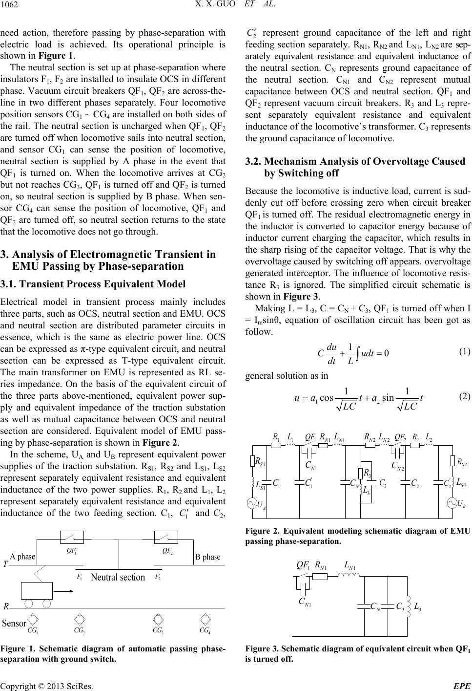 X. X. GUO ET AL. 1062 need action, therefore passing by phase-separation with electric load is achieved. Its operational principle is shown in Figure 1. The neutral section is set up at phase-separation where insulators F1, F2 are installed to insulate OCS in different phase. Vacuum circuit breakers QF1, QF2 are across-the- line in two different phases separately. Four locomotive position sensors CG1 ~ CG4 are installed on both sides of the rail. The neutral section is uncharged when QF1, QF2 are turned off when locomotive sails into neutral section, and sensor CG1 can sense the position of locomotive, neutral section is supplied by A phase in the event that QF1 is turned on. When the locomotive arrives at CG2 but not reaches CG3, QF1 is turned off and QF2 is turned on, so neutral section is supplied by B phase. When sen- sor CG4 can sense the position of locomotive, QF1 and QF2 are turned off, so neutral section returns to the state that the locomotive does not go through. 3. Analysis of Electromagnetic Transient in EMU Passing by Phase-separation 3.1. Transient Process Equivalent Model Electrical model in transient process mainly includes three parts, such as OCS, neutral section and EMU. OCS and neutral section are distributed parameter circuits in essence, which is the same as electric power line. OCS can be expressed as π-type equivalent circuit, and neutral section can be expressed as T-type equivalent circuit. The main transformer on EMU is represented as RL se- ries impedance. On the basis of the equivalent circuit of the three parts above-mentioned, equivalent power sup- ply and equivalent impedance of the traction substation as well as mutual capacitance between OCS and neutral section are considered. Equivalent model of EMU pass- ing by phase-separation is shown in Figure 2. In the scheme, UA and UB represent equivalent power supplies of the traction substation. RS1, RS2 and LS1, LS2 represent separately equivalent resistance and equivalent inductance of the two power supplies. R1, R2 and L1, L2 represent separately equivalent resistance and equivalent inductance of the two feeding section. C1, 1 C and C2, T R 1 QF 2 QF 1 CG 2 CG 3 CG 4 CG 1 F 2 F 2 C represent ground capacitance of the left and right feeding section separately. RN1, RN2 and LN1, LN2 are sep- arately equivalent resistance and equivalent inductance of the neutral section. CN represents ground capacitance of the neutral section. CN1 and CN2 represent mutual capacitance between OCS and neutral section. QF1 and QF2 represent vacuum circuit breakers. R3 and L3 repre- sent separately equivalent resistance and equivalent inductance of the locomotive’s transformer. C3 represents the ground capacitance of locomotive. 3.2. Mechanism Analysis of Overvoltage Caused Becas inductive load, current is sud- by Switching off use the locomotive i denly cut off before crossing zero when circuit breaker QF1 is turned off. The residual electromagnetic energy in the inductor is converted to capacitor energy because of inductor current charging the capacitor, which results in the sharp rising of the capacitor voltage. That is why the overvoltage caused by switching off appears. overvoltage generated interceptor. The influence of locomotive resis- tance R3 is ignored. The simplified circuit schematic is shown in Figure 3. Making L = L3, C = CN + C3, QF1 is turned off when I = Isinθ, equation o mf oscillation circuit has been got as follow. 1du 0Cudt dt L (1) general solution as in 1 cosua 2 11 sinta t L CLC (2) 1 QF 1S R 1S L A U 1 R1 L 1 C ' 1 C 1N R 1N L N C 2 C 2N R 2N L 3 R 3 L 2S R 2S L B U 2 QF 2 R 2 L ' 2 C 1N C 2N C 3 C Figure 2. Equivalent modeling schematic diagram of EMU passing phase-separation. 1 N N L R 1 QF 1 C Figure 1. Schematic diagramof automatic passing phase- separation with ground switch. N C 3 C 3 L N 1 Figure 3. Schematic diagram of equivalent circuit when QF1 is turned off. Copyright © 2013 SciRes. EPE 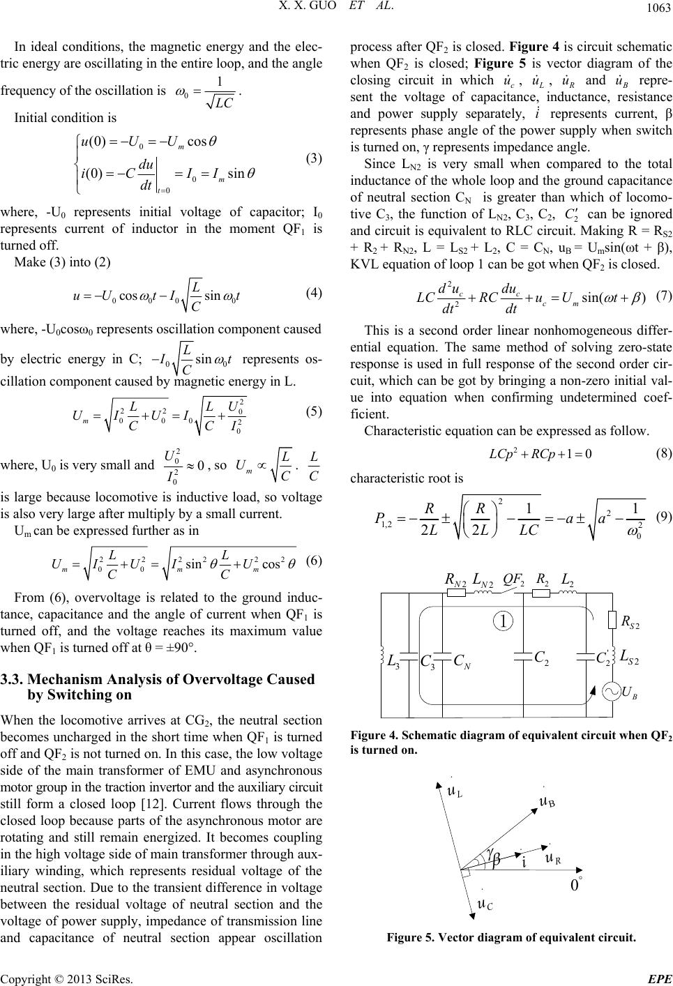 X. X. GUO ET AL. 1063 In ideal conditions, the magnetic energy and the elec- tric energy are oscillating in the entire loop, and the angle frequency of the oscillation is 0 1 LC . Initial condition is 0 0 0 (0)ucos (0) sin m m t UU du iC II dt (3) where, -U0 represents initial voltage of capacitor; I0 represents current of inductor in the moment QF1 is turned off. Make (3) into (2) 000 cos sin L 0 tI t C uU (4) where, -U0cosω0 represents oscillation com ponent caused by electric energy in C; 00 sin L I t C represents os- cillation component causednergy in L. by magnetic e 2 22 0 000 2 m U LL UIUI ( 0 CC I5) where, U0 is very small and 2 0 2 0 0 U I, so mL UC . L C is large because locomotive is in load, e ductiveso voltag is also very large after multiply by a small current. Um can be expressed further as in 2222 22 00 sin cos mmm LL UIUI U CC (6) From (6), overvoltage is related to the ground induc- tance, capacitance and the angle of current when QF is turned off, and the voltage reaches its maximum v when QF1 is turned off at θ = ±90°. 2, the neutral section side mer of EMU and asynchronous 1 alue 3.3. Mechanism Analysis of Overvoltage Caused by Switching on When the locomotive arrives at CG becomes uncharged in the short time when QF1 is turned off and QF2 is not turned on. In this case, the low voltage of the main transfor motor group in the traction invertor and the auxiliary circuit still form a closed loop [12]. Current flows through the closed loop because parts of the asynchronous motor are rotating and still remain energized. It becomes coupling in the high voltage side of main transformer through aux- iliary winding, which represents residual voltage of the neutral section. Due to the transient difference in voltage between the residual voltage of neutral section and the voltage of power supply, impedance of transmission line and capacitance of neutral section appear oscillation process after QF2 is closed. Figure 4 is circuit schematic when QF2 is closed; Figure 5 is vector diagram of the closing circuit in which c u , L u , R u and B u repre- sent the voltage of capacitance, inductance, resistance and power supply separately, i represents current, β represents phase angle of the power supply when switch is turned on, γ represents imedance ale. Since LN2 is very small when compared to the total inductance of the whole loop and the ground capacitance of neutral section CN is greater than which of locomo- tive C3, the function of LN2, C3, C2, 2 C can p ng be ignored and circuit is equivalent to RLC circuit. Making R = RS2 + R2 + RN2, L = LS2 + L2, C = CN, uB = Umsin(ωt + β), KVL equation of loop 1 can be got when QF2 is closed. 2 2sin( ) cc cm du du LCRCu Ut dt dt (7) This is a second order linear nonhomogeneous differ- ential equation. The same method of solving zero-state response is used in full response of the second order cuit, which can be got by bringing a non-zero initial val- ue ristic root is cir- into equation when confirming undetermined coef- ficient. Characteristic equation can be expressed as follow. 210LCp RCp (8) characte 211RR 2 2 a 1,2 0 22 Pa LL LC (9) 3 C 2 C 2N R 2N L 3 L 2S R 2S L B U 2 QF 2 R 2 L ' 2 C N C Figure 4. Schematic diagram of equivalent circuit when QF2 is turned on. C u i R u ° 0 B u L u Figure 5. Vector diagram of equivalent circuit. Copyright © 2013 SciRes. EPE 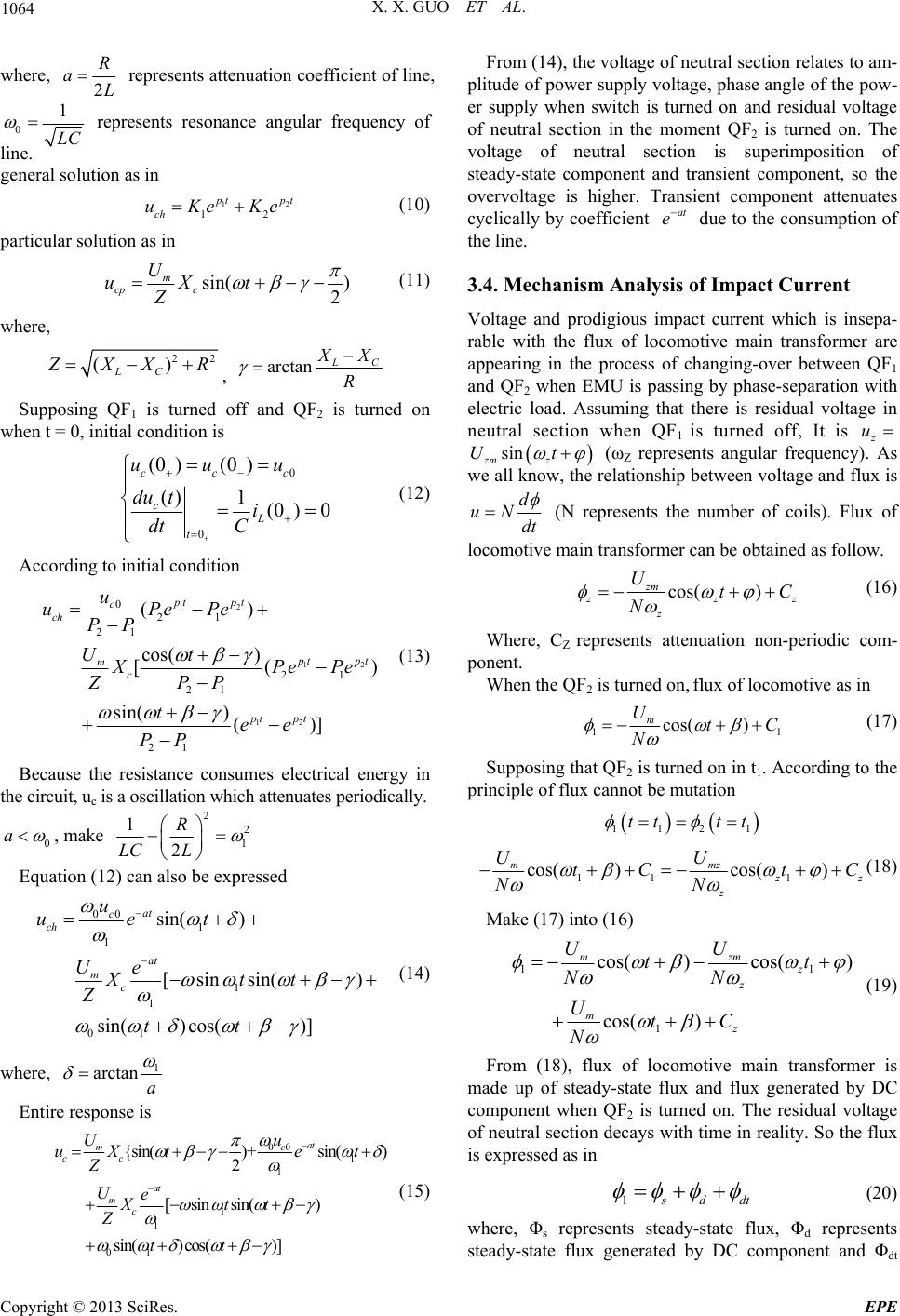 X. X. GUO ET AL. 1064 where, 2 R aL represents attenuation coefficient of line, 0 1 LC line. represents resonance angular frequency of general solution as in (10) particular solution as in 12 12 pt pt ch uKeKe sin( ) 2 c m U uXt cp Z (11) where, 22 () LC Z XX R , arctan L C X X R turned off and QF2 is turned on when t = 0, initial condition is Supposing QF1 is 0 0 (0 ) c u (0 ) () 1(0 ) 0 cc cL t uu du ti dt C (12) ding to initial condition Accor 12 12 12 0 21 21 cos( ) [21 21 21 () () sin() ()] pt t c ch p p tpt pt pt u uPeP PePe ZPP tee PP Because the resistance consumes electrical energy in th enuates periodically. mc PP Ut X (13) e e circuit, uc is a oscillation which att 0 a , make 2 2 1 1 2 R LC L Equation (12) can also be expressed 00 1 1 1 1 01 sin() cos()] Z tt sin( ) [sinsin() at c ch at mc u uet Ue Xtt (14) where, 1 arctan a Entire response is 00 1 1 1 1 01 {sin()+sin() 2 [sinsin( ) sin() cos()] at mc cc at mc Uu uXte t Z Ue Xtt Z tt (15) From (14), the voltage of neutral section relates to am- plitude of power supply voltage, phase angle of the pow- er supply when switch is turned on and residual voltage of neutral section in the moment QF2 is turned o voltage of neutral section is superimposition of steady-state component and transient component, so the overvoltage is higher. Transient component attenuates y by coefficit n. The cyclicallen at e due to the consumption of 3.4. Mechanism Analysis of Impact Current Voltage and prodigious impact current which is insepa- rable with the flux of locomotive main transform appearing in the process of changing-over between QF1 and QF2 when EMU is passing by phase-separation with electric load. Assuming that there is residual voltage in ne the line. er are utral section when QF1 is turned off, It is z u sin zm z Ut (ωZ represents angular frequency). As we all know, the relationship between voltage and flux is d uN dt (N represents the number of coils). Flux of locomotive main transformer can be obtained as follow. cos( ) zm z zz UtC N z (16) Where, CZ represents attenuation non-periodic c ponent. om- When the QF2 is turned on, flux of locomotive as in 11 cos( ) m UtC N (17) Supposing that QF2 is turned on in t1. According to the principle of flux cannot be mutation 1121 tt tt 11 1 s( )cos()co mmz z z z tC tC N UU N (18) Make (17) into (16) 11 1 cos( )cos() z cos( ) mz UtC mzm z UU tt NN N (19) is made up of steady-state flux and flux generated b component when QF2 is turned on. The ltage of From (18), flux of locomotive main transformer y DC residual vo neutral section decays with time in reality. So the flux is expressed as in 1 s ddt (20) where, Φs represents steady-state flux, Φd represents steady-state flux generated by DC component and Φdt Copyright © 2013 SciRes. EPE  X. X. GUO ET AL. 1065 represents damped flux generated by DC component. 1m R IN (21) where, N represents the number of coils and Rm repre- sents total reluctance. When β meet ωt + β = β + 2kT, Φ1 will reac maximum 2Φs + Φdt, and inrush current increases greatly. Impact current which up to 4-6 times as much as the ra 4.1. Simulation Analysis of Overvoltage 1 = 0.48 Ω, L1 = 4.76 mH, R2 = 0 RN = 0.151 Ω and LN = 1.47 mH; CN = 0.01155 μF, CN1 = 4. (θ = 0°); Figure 6(b) shows the voltage waveform when the am- For inductive which of the 0°. that QF1 ltage Caused by Switching on of thltage of neutral section which is - m supply voltage and operating conditions when electromagnetic transient process oc- h the ted current in closing side is the superposition of the inrush current and low-voltage side current. 4. Simulation of EMU Passing by Phase-separation Making use of Matlab/Simulink to establish the module of passing by phase-separation with electric load. Simu- lation parameters are shown as follow. RS1 = 0.6969 Ω, LS1 = 4.17 mH, RS2 = 0.3676 Ω and LS2 = 24.9 mH; R .3836 Ω and L2 = 3.73 mH; 0.000325 μF and CN2 = 0.00415 μF. 1.1. Simulation Anal y si s of Overv ol tage Caus ed b y Switching off When QF1 is turned off, the simulation results of over- voltage are shown in Figure 6: Figure 6(a) shows the voltage waveform when current crossing zero plitude of current is maximum (θ = ±90°). load, the phase angle of voltage is ahead of current 90°, so the angle of Ua is 90°when θ = The simulation results in Figure 6 indicate turned off causes a large overvoltage whose maximum can reach 77.41 kV. The amplitude of the overvoltage is related to the phase of current when QF1 is turned off, which is a good description of the correctness of the analysis of the mechanism. 4.1.2. Simulation An al ys i s of Overv o When QF2 is turned on in this process, the absolute value e maximum vo shown in Table 1 can be got through simulating in the condition that phase angle β is 0°- 350°. As can be seen from I, overvoltage minimum appears when β is in the vicinity of 10°or 180°; overvoltage maximum is appearing when β in the vicinity of 90°or 270°. The waveforms of overvoltage minimum and maxi um are shown in Figure 7: Figure 7(a) β = 180°, Figure 7( b) β = 270°. The simulation results in Figure 7 indicate that QF2 turned on causes a large overvoltage whose maximum can reach 77.68 kV. The amplitude of the overvoltage is related to the phase of power curs. 00.1 0.2 0.3 0.4 0.5 -6 -4 -2 0 2 4 6x 1 0 4 t/s Neuter-ral section ovvoltage/kV (a) QF1 is turned off when the phase angle of Ua is 90°(θ = 0°) 00.1 0.2 0.3 0.40.5 -6 -4 -2 0 2 4 6 8x 1 04 t/s Neutral section over-volt (b) QF1 is turned off when the phase angle of Ua is 0°(θ = -90°) Figure 6. Overvoltage waveforms when QF1 is turned off. Ta - tion.. β(°) 0 10 20 30 40 50 age/kV ble 1. Absolute value of peak overvoltage of neutral sec U(kV)45.90 40.92 41.94 47.23 52.5357.60 β(°) 60 70 80 90 100 110 U(kV)62.23 66.2569.48 71.11 70.4867.60 β(°) 120 130 140 150 160 170 U(kV)62.58 58.29 56.09 53.15 49.6245.38 β(°) 180 190 200 210 220 230 U(kV)40.60 42.15 47.50 52.92 58.3863.64 β(°) 240 250 260 270 280 290 U(kV)68.45 72.64 76.05 77.68 77.0574.18 β(°) 300 310 320 330 340 350 U(kV)69.15 62.93 60.85 58.02 54.6450.56 Copyright © 2013 SciRes. EPE  X. X. GUO ET AL. 1066 00.1 0.2 0.3 0.4 0.5 0.6 0.7 0.8 -8 -6 -4 -2 0 2 4 6 8x 1 0 4 Neu tral sectkV t/s ion over-voltage/ ned o0° (a) QF2 is turn when the phase angle of Ub is 18 00.1 0.2 0.3 0.4 0.5 0.6 0.7 0.8 -8 -6 -4 -2 0 2 4 6 8x 10⁴ t/s Neutral sec tion over-voltage/kV (b) QF2 is turned on when the phase angle of Ua is 270° Figure 7. Overvoltage waveforms when QF2 is turned on. The protection gap on the locomotive roof discharges because of overvoltage, which results in traction substa- tion tripping and interrupting power supply and trans- portation. The frequent shocks of overvoltage have an influe erter nd auxiliary motor system. The overvoltage is related to oscillation caused by the changes in circuit parameters when circuit breaker is operating and voltage phase angle when switching on or off, thereby it can be suppressed effectively by eliminating oscillation in the condition of changing the circuit parameters. In addition, using phase- controlled rectification technology in switching on and off is an effective method. 4.2. Simulation Analysis of Impact Current I C 0 MVA, variable ratio is 220/27.5 kV; equivalent resis- ta residual voltage of neutral section and overvoltage caused gle when QF2 is turned on. Impact current whose amplitude is 5 times higher than n of the t. Wave- nce on the life of traction transformers, conv a nfluence on Differential Protection apacity of traction transformer adopted in simulation is 4 nce and inductance of feeding section in both sides of phase-separation are 4.475 Ω and 19.35 mH; equivalent resistance and inductance of neutral section is 0.063 Ω and 0.198 mH; capacity of main transformer of EMU is 8MVA, variable ratio is 27.5/1.5 kV. Excitation inrush current of the EMU transformer is shown in Figure 8 when QF2 is turned on, and inrush current of the EMU transformer closing side is shown in Figure 9. As can be seen from the simulation results: the core of EMU main transformer is saturation under the action of by switching off, which comes into being excitation in- rush current whose amplitude is high and waveform ex- ists obvious discontinuity an that of rated current in closing side is the superpositio inrush current and low-voltage side curren form does not exist obvious discontinuity angle, however waveform generates obvious distortion because of non- periodic component. Making use of the CT model in PSCAD, impact cur- rent is flowing into the low-voltage side of traction transformer directly, and the secondary current of high and low sides of traction transformer can be got. CT pa- rameter settings: CT ratio of low-voltage side k = 2000/5 A, l = 0.5 m, S = 51.2 cm2, R = 0.13 Ω; CT ratio of high-voltage side k = 250/5 A, l = 0.7 m, S = 23.2 cm2, R = 0.06 Ω. The impact current is imported into the pri- mary side of CT, secondary current of CT is shown in Figure 10. From Figure 10, due to the fact that the flux of CT core does not mutation, the waveform of secondary cur- rent does not show obvious distortion in the moment of closing. Then the waveform of secondary current is dis- torted because of CT core saturation, which is under the action of non-periodic component. The transmission characteristics of traction transformer between steady- state cycle component and non-periodic component is different, so there is a large difference in the non-peri- odic component of both sides. The non-periodic compo- nent of current in high-voltage side is much smaller than 00.05 0.1 0.15 0.2 0.25 0.3 0 500 1000 1500 2000 2500 3000 t/s Figure 8. Excitation inrush current of the EMU transformer. Excitation inrush/A 00.05 0.1 0.15 0.2 0.25 0.3 0 500 1000 1500 2000 2500 3000 Inru sh cu rren t/A t/s Figure 9. Inrush current of the EMU transformer closing side. Copyright © 2013 SciRes. EPE  X. X. GUO ET AL. 1067 that of current in low-voltage side. Therefore, the wave- form of CT secondary current of high-voltage side does not contain any distortion. Figure 11 shows waveform of the differential current flowing in the differential relay, which indicates that the differential current distortion within the first few cycles after closing is obvious, primarily because that the non- periodic component of impact current is not attenuated sufficiently. After a period of time, the non-periodic rier transformation, and the result is Figure 12. Figure 12 shows that in the first cycle, the second harmonic content is reducing continuously, which is re- lated to that CT secondary current of low-voltage side of traction transformer does not appear obvious distortion in component of the current is almost attenuation finished. The second harmonic of the differential current is ana- zed by using Fouly shown in 00.05 0.1 0.15 0.2 0.25 0.3 -5 0 5 10 15 20 t/s (a) CT secondary current in low voltage side of traction transformer C T secondary current/A 00.05 0.1 0.15 0.20.250.3 -6 -4 -2 0 2 4 6 8 t/s C T (b) CT secondary current in high voltage side of traction transformer Figure 10. CT secondary current. secondary current/A 00.05 0.1 0.15 0.2 0.25 0.3 -10 -5 0 5 10 15 20 t/s 00.05 0.1 0.150.2 0.25 0.3 0 0.2 0.4 0.6 0.8 t/s Second harmonic am plitude percentage/% F ferential cu r the first cycle. Subsequently, the second harmonic con- tent increases with the distortion of the waveform. The second harmonic content is less than 15% below its set value (15% to 20%) in 0.15s after closing, so protection cannot latch and differential protection of traction trans- former is misoperation. According to the analysis above, the impact current can cause traction transformer differential protection misoperation. For the misoperation caused by that second harmonic content is low, using dual scheme in different tial pe waveform recognition atresia criterion. 5. Conclusions Mechanism of overvoltage and impact current in the electromagnetic transient process of passing by phase-separation with electric load is studied in the round in this article, and the equivalent model is built for each of the transient process, which can be used to analyze overvoltage and impact current. Suppressing overvoltage by changing the parameters of the circuit and using isoperation caused by impact current EFERENCES igure 12. Second harmonic amplitude percentage in dif- rent. - rotection can solve the problem by increasing th phase-controlled rectifier technology is proposed; differ- ential protection m is solved by increasing the waveform recognition atresia criterion. So the article provides a reference for subse- quent studies, and the resonance overvoltage in this tran- sient process is more complicated, which needs further analysis in later period. 6. Acknowledgements The authors express sincere gratitude to the support of China National Natural Science Fund (50907055, U1134205 and 51177139) and Fundamental Research Funds for the Central Universities. D ifferen tial c urren t/A Figure 11. Waveform of the differential current. R [1] X. C. Chen, “Railway Power Supply Relay Protection and Automation,” China Railway Press, 2010. [2] J. Z. Wei, X. X. Guo and Z. Q. Han, “Protection on the Copyright © 2013 SciRes. EPE  X. X. GUO ET AL. Copyright © 2013 SciRes. EPE 1068 res of Feeder Protection Agains Wrong-phase Short Circuit for AC Traction Substation,” Society, Vol. 4, 2000, pp imulation of Exc Surge Current in Electric Locomotive and Analysis of In- , X. Li and B. Liu, “Research on Transient Proc- during Auto-passing Phase of Electric Locomo- un, S. X. Shan and G. F. Zheng, “Comparsion . Wu, “High Speed EMU Condition of EMU Passing by Phase-separation with Electric Load in High-speed Railway,”APAP2011, 2011,10. [3] Z. Q. Han, “Study on Dynamic Process and Feeder Pro- tection on the Condition of EMU Passing by Phase- sepa- ration with Electric Load in High-speed Railway,” Aca- demic trends, Vol. 4, 2008, pp.10-12. [4] Z. Z. Li, “Analysis of Causes of Tripping during Electric locomotive’s Passage of Neutral Section and Study of Its Prevention Measures,” Electric Railway, Vol. 4, 2008, pp. 10-12. [5] S. B. Gao, Y. F. Wang and J. Zhang, “Analysis on Fault and Operating Featut . Journal of The China Railway 24-27. [6] Y. H. Guo, J. S. Lian and K. L. Zhang, “Influnce of Auto-passing of Neutral Section on Electric Locomotive,” Electric Drive For Locomotive, Vol. 2, 2000, pp. 13-15. [7] G. Ma, G. N. Wu and T. Wang, “Sitation Modeling Based on the Measured Data,” Sustainable Power Generation and Supply, 2009. fluence to Public Grid,” Electric Railway, Vol. 1, 2010, pp.1-4. [8] W. Ran ess of Ground’s Auto-Passing Neutral Section at Switch- ing Time,” Transactions of China Electrotechnical Soci- ety, Vol.11, 2011, pp. 150-154. [9] L. Q. Luo, Y. Wang and G. Chang, “Analysis of Inrush Current tive,” Journal of Beijing Jiaotong University, Vol. 6, 2011, pp.57-61. [10] H. L. Weng, X. N. Lin and P. Liu, “A Novel Explanation to the Mal-operation of Differential Protection during the Loaded Transformer Energization,” Proceeding of the CSEE, Vol. 26, 2006, pp. 27-32. [11] W. Q. S between Home and Aboard of Automatic Passing over of Neutral Section Device,” Electric Railway, Vol. 2, 2002, pp. 12-16. [12] S. B. Yang, M. Huang and M. L |