Paper Menu >>
Journal Menu >>
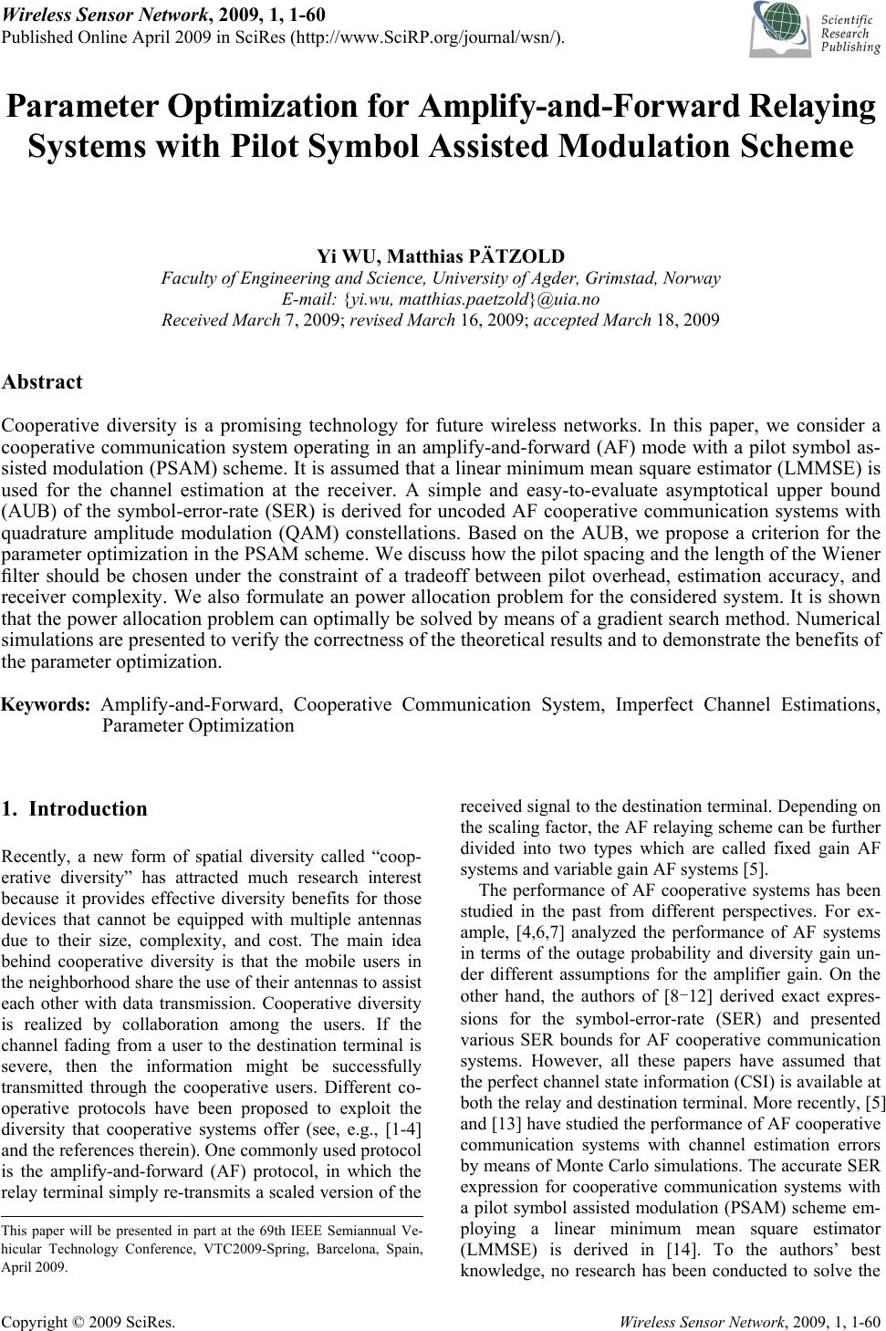 Wireless Sensor Network, 2009, 1, 1-60 Published Online April 2009 in SciRes (http://www.SciRP.org/journal/wsn/). Copyright © 2009 SciRes. Wireless Sensor Network, 2009, 1, 1-60 Parameter Optimization for Amplify-and-Forward Relaying Systems with Pilot Symbol Assisted Modulation Scheme Yi WU, Matthias PÄTZOLD Faculty of Engineering and Science, University of Agder, Grimstad, Norway E-mail: {yi.wu, matthias.paetzold}@uia.no Received March 7, 2009; revised March 16, 2009; accepted March 18, 2009 Abstract Cooperative diversity is a promising technology for future wireless networks. In this paper, we consider a cooperative communication system operating in an amplify-and-forward (AF) mode with a pilot symbol as- sisted modulation (PSAM) scheme. It is assumed that a linear minimum mean square estimator (LMMSE) is used for the channel estimation at the receiver. A simple and easy-to-evaluate asymptotical upper bound (AUB) of the symbol-error-rate (SER) is derived for uncoded AF cooperative communication systems with quadrature amplitude modulation (QAM) constellations. Based on the AUB, we propose a criterion for the parameter optimization in the PSAM scheme. We discuss how the pilot spacing and the length of the Wiener filter should be chosen under the constraint of a tradeoff between pilot overhead, estimation accuracy, and receiver complexity. We also formulate an power allocation problem for the considered system. It is shown that the power allocation problem can optimally be solved by means of a gradient search method. Numerical simulations are presented to verify the correctness of the theoretical results and to demonstrate the benefits of the parameter optimization. Keywords: Amplify-and-Forward, Cooperative Communication System, Imperfect Channel Estimations, Parameter Optimization 1. Introduction Recently, a new form of spatial diversity called “coop- erative diversity” has attracted much research interest because it provides effective diversity benefits for those devices that cannot be equipped with multiple antennas due to their size, complexity, and cost. The main idea behind cooperative diversity is that the mobile users in the neighborhood share the use of their antennas to assist each other with data transmission. Cooperative diversity is realized by collaboration among the users. If the channel fading from a user to the destination terminal is severe, then the information might be successfully transmitted through the cooperative users. Different co- operative protocols have been proposed to exploit the diversity that cooperative systems offer (see, e.g., [1-4] and the references therein). One commonly used protocol is the amplify-and-forward (AF) protocol, in which the relay terminal simply re-transmits a scaled version of the received signal to the destination terminal. Depending on the scaling factor, the AF relaying scheme can be further divided into two types which are called fixed gain AF systems and variable gain AF systems [5]. The performance of AF cooperative systems has been studied in the past from different perspectives. For ex- ample, [4,6,7] analyzed the performance of AF systems in terms of the outage probability and diversity gain un- der different assumptions for the amplifier gain. On the other hand, the authors of [8-12] derived exact expres- sions for the symbol-error-rate (SER) and presented various SER bounds for AF cooperative communication systems. However, all these papers have assumed that the perfect channel state information (CSI) is available at both the relay and destination terminal. More recently, [5] and [13] have studied the performance of AF cooperative communication systems with channel estimation errors by means of Monte Carlo simulations. The accurate SER expression for cooperative communication systems with a pilot symbol assisted modulation (PSAM) scheme em- ploying a linear minimum mean square estimator (LMMSE) is derived in [14]. To the authors’ best knowledge, no research has been conducted to solve the This paper will be presented in part at the 69th IEEE Semiannual Ve- hicular Technology Conference, VTC2009-Spring, Barcelona, Spain, April 2009. 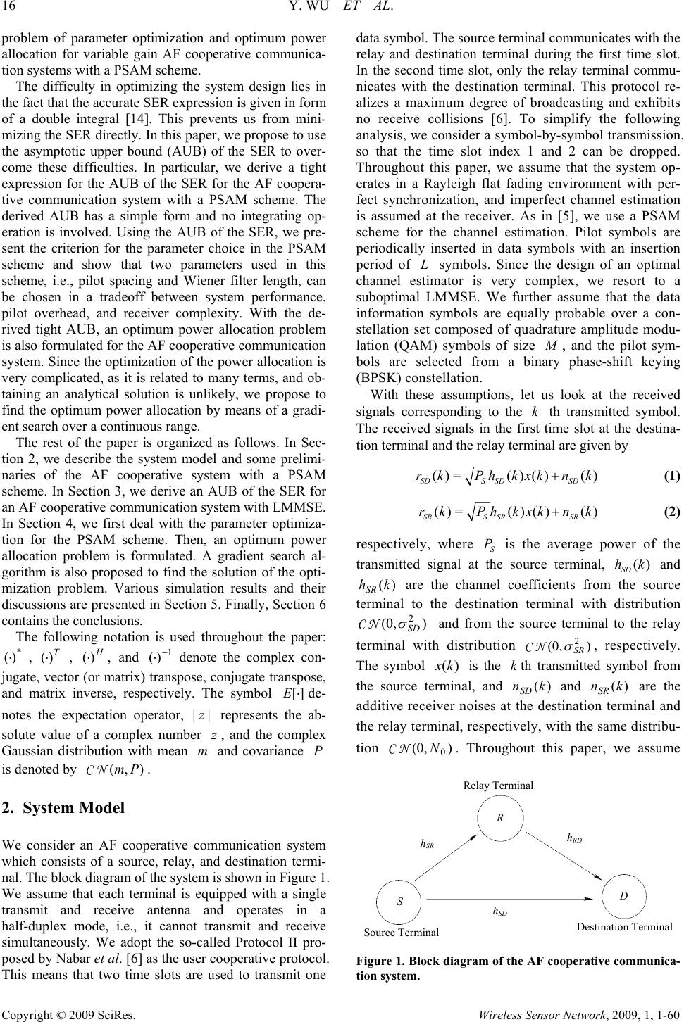 16 Y. WU ET AL. Copyright © 2009 SciRes. Wireless Sensor Network, 2009, 1, 1-60 problem of parameter optimization and optimum power allocation for variable gain AF cooperative communica- tion systems with a PSAM scheme. The difficulty in optimizing the system design lies in the fact that the accurate SER expression is given in form of a double integral [14]. This prevents us from mini- mizing the SER directly. In this paper, we propose to use the asymptotic upper bound (AUB) of the SER to over- come these difficulties. In particular, we derive a tight expression for the AUB of the SER for the AF coopera- tive communication system with a PSAM scheme. The derived AUB has a simple form and no integrating op- eration is involved. Using the AUB of the SER, we pre- sent the criterion for the parameter choice in the PSAM scheme and show that two parameters used in this scheme, i.e., pilot spacing and Wiener filter length, can be chosen in a tradeoff between system performance, pilot overhead, and receiver complexity. With the de- rived tight AUB, an optimum power allocation problem is also formulated for the AF cooperative communication system. Since the optimization of the power allocation is very complicated, as it is related to many terms, and ob- taining an analytical solution is unlikely, we propose to find the optimum power allocation by means of a gradi- ent search over a continuous range. The rest of the paper is organized as follows. In Sec- tion 2, we describe the system model and some prelimi- naries of the AF cooperative system with a PSAM scheme. In Section 3, we derive an AUB of the SER for an AF cooperative communication system with LMMSE. In Section 4, we first deal with the parameter optimiza- tion for the PSAM scheme. Then, an optimum power allocation problem is formulated. A gradient search al- gorithm is also proposed to find the solution of the opti- mization problem. Various simulation results and their discussions are presented in Section 5. Finally, Section 6 contains the conclusions. The following notation is used throughout the paper: * )(⋅ , T )(⋅ , H )(⋅, and 1 )( − ⋅ denote the complex con- jugate, vector (or matrix) transpose, conjugate transpose, and matrix inverse, respectively. The symbol ][ ⋅ Ede- notes the expectation operator, || z represents the ab- solute value of a complex number z , and the complex Gaussian distribution with mean m and covariance P is denoted by ),( PmNC . 2. System Model We consider an AF cooperative communication system which consists of a source, relay, and destination termi- nal. The block diagram of the system is shown in Figure 1. We assume that each terminal is equipped with a single transmit and receive antenna and operates in a half-duplex mode, i.e., it cannot transmit and receive simultaneously. We adopt the so-called Protocol II pro- posed by Nabar et al. [6] as the user cooperative protocol. This means that two time slots are used to transmit one data symbol. The source terminal communicates with the relay and destination terminal during the first time slot. In the second time slot, only the relay terminal commu- nicates with the destination terminal. This protocol re- alizes a maximum degree of broadcasting and exhibits no receive collisions [6]. To simplify the following analysis, we consider a symbol-by-symbol transmission, so that the time slot index 1 and 2 can be dropped. Throughout this paper, we assume that the system op- erates in a Rayleigh flat fading environment with per- fect synchronization, and imperfect channel estimation is assumed at the receiver. As in [5], we use a PSAM scheme for the channel estimation. Pilot symbols are periodically inserted in data symbols with an insertion period of L symbols. Since the design of an optimal channel estimator is very complex, we resort to a suboptimal LMMSE. We further assume that the data information symbols are equally probable over a con- stellation set composed of quadrature amplitude modu- lation (QAM) symbols of size M , and the pilot sym- bols are selected from a binary phase-shift keying (BPSK) constellation. With these assumptions, let us look at the received signals corresponding to the k th transmitted symbol. The received signals in the first time slot at the destina- tion terminal and the relay terminal are given by ()=()() () SDS SDSD rkPhkxk nk+ (1) ()=()() () SRS SRSR rkPhkxk nk+ (2) respectively, where S P is the average power of the transmitted signal at the source terminal, () SD hk and )( khSR are the channel coefficients from the source terminal to the destination terminal with distribution )(0, 2 SD σ NC and from the source terminal to the relay terminal with distribution )(0, 2 SR σ NC, respectively. The symbol )(kx is the kth transmitted symbol from the source terminal, and )(kn SD and )(knSR are the additive receiver noises at the destination terminal and the relay terminal, respectively, with the same distribu- tion )(0, 0 NNC. Throughout this paper, we assume Figure 1. Block diagram of the AF cooperative communica- tion system. Relay Terminal hSR hRD hSD SD R Source TerminalDestination Terminal Relay Terminal 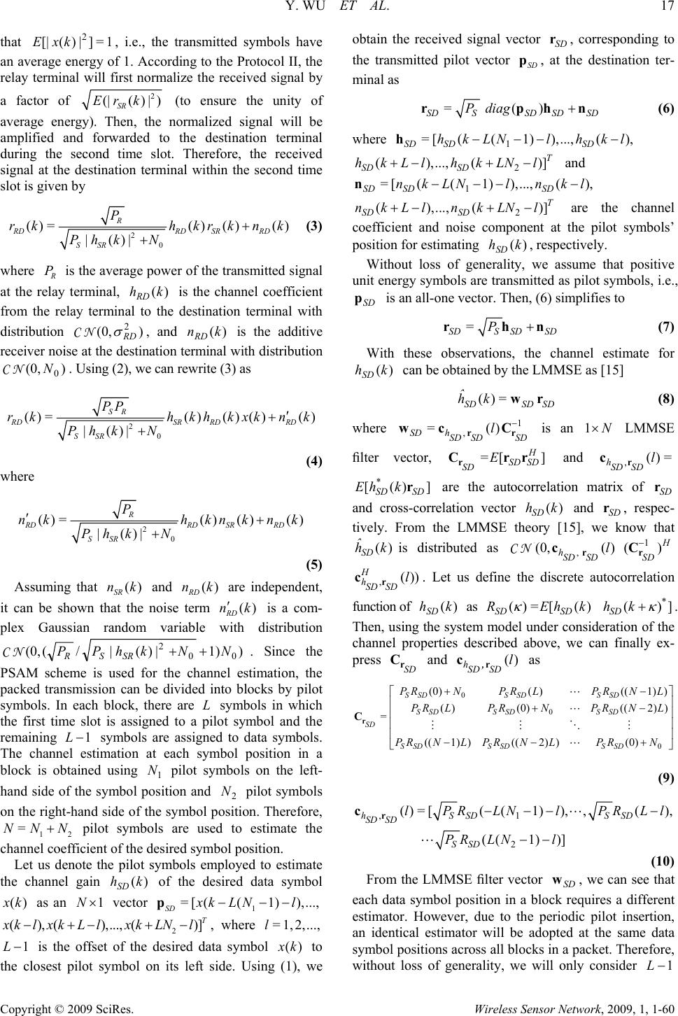 Y. WU ET AL. 17 Copyright © 2009 SciRes. Wireless Sensor Network, 2009, 1, 1-60 that 1=]|)([| 2 kxE , i.e., the transmitted symbols have an average energy of 1. According to the Protocol II, the relay terminal will first normalize the received signal by a factor of 2 (|() |) SR Er k (to ensure the unity of average energy). Then, the normalized signal will be amplified and forwarded to the destination terminal during the second time slot. Therefore, the received signal at the destination terminal within the second time slot is given by 2 0 ()=() ()() |()| R RDRD SRRD SSR P rkhkrk nk Ph kN + + (3) where R P is the average power of the transmitted signal at the relay terminal, )(khRD is the channel coefficient from the relay terminal to the destination terminal with distribution )(0, 2 RD σ NC , and )(knRD is the additive receiver noise at the destination terminal with distribution )(0, 0 NNC. Using (2), we can rewrite (3) as 2 0 ()=() ()()() |()| SR RDSR RDRD SSR PP rkhkhkxk nk Ph kN ′ + + (4) where 2 0 ()=()()() |()| R RDRD SRRD SSR P nk hknknk Ph kN ′+ + (5) Assuming that () SR nk and () RD nk are independent, it can be shown that the noise term () RD nk ′ is a com- plex Gaussian random variable with distribution )1)|)(|/((0, 00 2NNkhPP SRSR++NC . Since the PSAM scheme is used for the channel estimation, the packed transmission can be divided into blocks by pilot symbols. In each block, there are L symbols in which the first time slot is assigned to a pilot symbol and the remaining 1−L symbols are assigned to data symbols. The channel estimation at each symbol position in a block is obtained using 1 N pilot symbols on the left- hand side of the symbol position and 2 N pilot symbols on the right-hand side of the symbol position. Therefore, 12 =NNN+ pilot symbols are used to estimate the channel coefficient of the desired symbol position. Let us denote the pilot symbols employed to estimate the channel gain )(khSD of the desired data symbol )(kx as an 1×N vector 1 = [((1)),..., SD xk LNl−−−p 2 ( ),(),...,()] T x klxkLlxk LNl−+− +−, where =1, 2,...,l 1L− is the offset of the desired data symbol )(kx to the closest pilot symbol on its left side. Using (1), we obtain the received signal vector SD r, corresponding to the transmitted pilot vector SD p, at the destination ter- minal as =() SDSSD SDSD Pdiag +rphn (6) where 1 = [((1)),...,(), SD SDSD hkLNlhkl − −− −h 2 (),..., ()]T SD SD hkLlhkLNl+−+− and 1 = [((1)),...,(), SD SDSD nkLNl nkl − −− −n 2 (),...,( )] T SD SD nkLl nkLNl+−+ − are the channel coefficient and noise component at the pilot symbols’ position for estimating )(khSD , respectively. Without loss of generality, we assume that positive unit energy symbols are transmitted as pilot symbols, i.e., SD p is an all-one vector. Then, (6) simplifies to = SDS SDSD P+rhn (7) With these observations, the channel estimate for )(khSD can be obtained by the LMMSE as [15] ()= SDSD SD ˆ hk wr (8) where 1 , =() SD hSDSDSD l− rr wc C is an 1N× LMMSE filter vector, =[ ] H SD SD SD E r Crr and ,()= hSDSD l r c * [()] SD SD Eh kr are the autocorrelation matrix of SD r and cross-correlation vector () SD hk and SD r, respec- tively. From the LMMSE theory [15], we know that () SD ˆ hk is distributed as N C, N (0,() hSDSDl r c1 () H SD − r C ,()) H hSD SDl r c. Let us define the discrete autocorrelation function of )(khSD as ()=[ () SD SD REhk κ * ()] SD hk κ +. Then, using the system model under consideration of the channel properties described above, we can finally ex- press SD r C and () hSDSD l ,r c as 0 0 0 (0)( )((1) ) ()(0)(( 2)) = ((1) )((2) )(0) SSDSSD SSD SSD SSDSSD SD SSD SSDSSD P RN PRLPRNL P RLPRNPRNL PR NLPRNLPRN +− ⎡ ⎤ ⎢ ⎥ +− ⎢ ⎥ ⎢ ⎥ ⎢ ⎥ −− + ⎣ ⎦ r C L L MMOM L (9) ,1 2 ()=[((1)),,(), ((1))] hSSD SSD SD SD SSD lPRLNlPRLl PR LNl − −−− −− r cL L (10) From the LMMSE filter vector SD w, we can see that each data symbol position in a block requires a different estimator. However, due to the periodic pilot insertion, an identical estimator will be adopted at the same data symbol positions across all blocks in a packet. Therefore, without loss of generality, we will only consider 1 − L 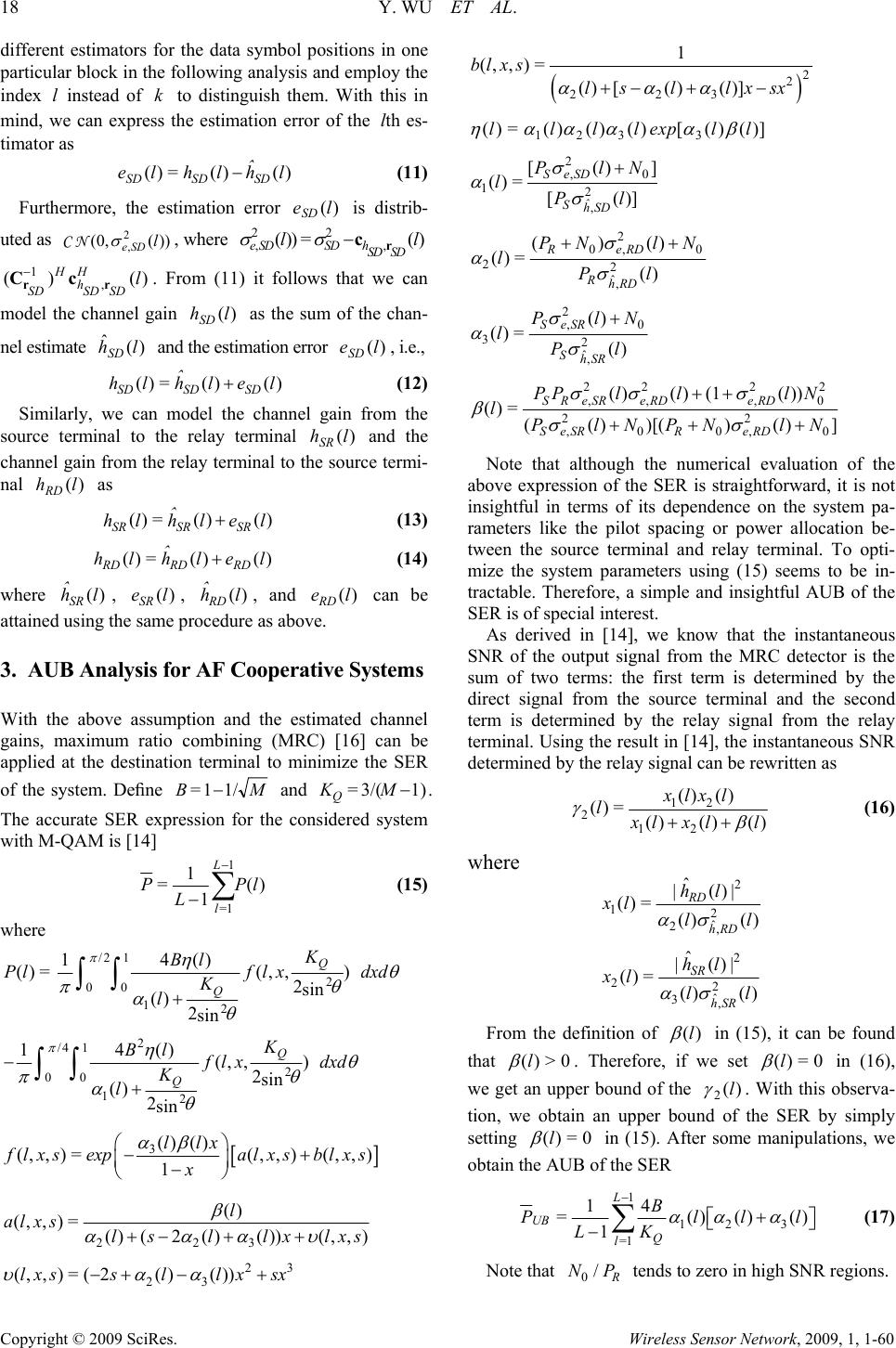 18 Y. WU ET AL. Copyright © 2009 SciRes. Wireless Sensor Network, 2009, 1, 1-60 different estimators for the data symbol positions in one particular block in the following analysis and employ the index l instead of k to distinguish them. With this in mind, we can express the estimation error of the l th es- timator as ()= ()() SDSD SD ˆ el hlhl − (11) Furthermore, the estimation error )(leSD is distrib- uted as ))((0,2 ,l SDe σ NC , where 22 ,, ())= () eSDSD h SD SD ll σσ −r c 1 , () () HH h SDSD SD l − rr Cc . From (11) it follows that we can model the channel gain )(lhSD as the sum of the chan- nel estimate )( ˆlhSD and the estimation error )(leSD , i.e., ()= ()() SDSD SD ˆ hl hlel+ (12) Similarly, we can model the channel gain from the source terminal to the relay terminal )(lhSR and the channel gain from the relay terminal to the source termi- nal )(lhRD as ()= ()() SRSR SR ˆ hl hlel + (13) ()= ()() RDRD RD ˆ hlhlel+ (14) where () SR ˆ hl , () SR el, () RD ˆ hl , and () RD el can be attained using the same procedure as above. 3. AUB Analysis for AF Cooperative Systems With the above assumption and the estimated channel gains, maximum ratio combining (MRC) [16] can be applied at the destination terminal to minimize the SER of the system. Define MB 1/1= − and 1)3/(= − MKQ. The accurate SER expression for the considered system with M-QAM is [14] 1 =1 1 =() 1 L l PPl L − −∑ (15) where =)(lP /2 1 2 00 12 14() (, ,) 2sin () 2sin Q Q K Bl f lx dxd K l π η θ πθ αθ + ∫∫ 2 /4 1 2 00 12 14() (, ,) 2sin () 2sin Q Q K Bl f lx dxd K l π η θ πθ αθ − + ∫∫ [] 3() () (,,)=(,,)(,,) 1 llx f lxsexpalxs blxs x αβ ⎛⎞ −+ ⎜⎟ − ⎝⎠ 223 () (,, )=()(2()())(,, ) l al xslsllx lxs β αααυ +− ++ 23 23 (,, )=(2()())lxssll xsx υαα −+−+ () 2 2 223 1 (,, )= () [()()] bl xs ls llxsx ααα +− +− 123 3 ()=()()()[() ()]llllexpll η αα ααβ 2 ,0 12 , [()] ()= [()] SeSD ˆ ShSD PlN lPl σ ασ + 2 0,0 22 ˆ, ()() ()= () ReRD RhRD PN lN lPl σ ασ ++ 2 ,0 32 ˆ, () ()= () SeSR ShSR PlN lPl σ ασ + 222 2 ,,, 0 22 ,00,0 ()() (1()) ()=(())[()()] SReSReRDeRD SeSRR eRD PPlllN lPlNPN lN σσ σ βσσ ++ ++ + Note that although the numerical evaluation of the above expression of the SER is straightforward, it is not insightful in terms of its dependence on the system pa- rameters like the pilot spacing or power allocation be- tween the source terminal and relay terminal. To opti- mize the system parameters using (15) seems to be in- tractable. Therefore, a simple and insightful AUB of the SER is of special interest. As derived in [14], we know that the instantaneous SNR of the output signal from the MRC detector is the sum of two terms: the first term is determined by the direct signal from the source terminal and the second term is determined by the relay signal from the relay terminal. Using the result in [14], the instantaneous SNR determined by the relay signal can be rewritten as 12 2 12 () () ()= ()() () xlx l l x lxll γ β ++ (16) where 2 12 ˆ 2, ˆ |()| ()= () () RD hRD hl xl ll ασ 2 22 ˆ 3, ˆ |()| ()= () () SR hSR hl xl ll ασ From the definition of )(l β in (15), it can be found that 0>)(l β . Therefore, if we set 0=)(l β in (16), we get an upper bound of the )( 2l γ . With this observa- tion, we obtain an upper bound of the SER by simply setting 0=)(l β in (15). After some manipulations, we obtain the AUB of the SER 1 12 3 =1 14 =()()() 1 L UB Q l B Plll LK ααα − + ⎡⎤ ⎣⎦ −∑ (17) Note that 0/R NP tends to zero in high SNR regions.  Y. WU ET AL. 19 Copyright © 2009 SciRes. Wireless Sensor Network, 2009, 1, 1-60 Therefore, the AUB of the SER can be further simplified as [] 1 12 3 =1 14 =()()() 1 L UB Q l B Plll LK ααα − ′+ −∑ (18) where 2 ,0 22 2 ˆ, () ()= () () ReRD RhRD PlN ll Pl σ αα σ + ′≈ As shown in Section 5, the AUB of the SER in (18) is very close to the exact SER, especially in high SNR regions. 4. Parameter Optimization As can be seen from (18), the AUB of the SER is deter- mined by the function 1 12 3 =1 ( ,,,)=()()() L SR l M LNP Plll ααα − ′+ ⎡⎤ ⎣⎦ ∑ (19) It should be pointed out that 123 (), (),()lll α αα ′, for =1,2, ,1lL−L are related to the parameters ,, , S LNP and R P. This can be deduced from their definition in (15). As a result, we establish the relation between the AUB of the SER and the parameters which need to be optimized. Using the above metric as an optimality crite- rion, we can now study the parameter optimization prob- lem of the considered system. In principle, we should optimize the four parameters ,, , S LNP and R P jointly to get the optimum system performance. However, the joint optimization problem is difficult to solve due to the form of the metric in (19). Therefore, we propose to op- timize the parameters of the PSAM and the power allo- cation separately as shown below. Although this method is suboptimal, our simulation results show that this method provides a satisfactory performance. 4.1. PSAM Parameter Optimization For the PSAM scheme, there exists a tradeoff between the system performance, pilot overhead, and receiver complexity. While a smaller pilot spacing L leads to a better channel estimation, the overhead imposed by the pilot symbols reduces the effective SNR and transmis- sion efficiency. A similar conflict also exists for the choice of the Wiener filter length N. A larger value of N is required to improve the channel estimation, but this will increase the receiver complexity. Therefore, the parameters L and N should be accordingly chosen by taking all these factors into account. We will use the metric in (19) as the optimality criterion for determining appropriate values of L and N. In particular, we will set /2== PPP RS , where P is the total transmitted power, and try to minimize the metric (, ,,) SR M LNP P which characterizes (asymptotically) the performance of the considered system. Since there is no closed-form solution to this minimization problem, the suitable values of L and N can only be obtained by examining the met- ric ),,,( RSPPNLM , which is presented in the next section. 4.2. Power Allocation Optimization Now, we will study the power allocation problem for the considered system. We assume that the parameters L, N are fixed and the total transmitted power is RS PPP + =. Under these constraints, we are going to optimize S P and R P so that the SER performance of the system is minimized. Since the metric ),,,( RS PPNLM characterizes (asymptotically) the SER performance of the considered system, we can state the power allocation problem as follows. Problem Statement: Given positive integers L, N, find a pair of real numbers S P and R P such that the metric function ),,,( RS PPNLM is minimized under the power constraint of the transmitted power which is fixed to P, i.e., , = {, }=(,, ,) SR SR PP SR PPP SR PParg minMLNPP + (20) Note that the derivatives of the metric ),,,( RS PPNLM with respect to S P and R P will be expressed as the sum of several high-order polynomials. This prevents us from finding a closed-form solution for S P and R P. Therefore, we propose to find the optimum power allocation by means of a gradient search over a con- tinuous range. 5. Numerical Results In this section, we will first verify by simulations the correctness of the derived expression found for the AUB of the SER. We will then present some examples illus- trating the parameter optimization procedure. We con- sider an AF cooperative communication system with 4-QAM modulation formats using the PSAM scheme for the channel estimation. Unless stated otherwise, the fol- lowing parameters are used in the numerical work. We set RS PP = and assume that the variance of the noise was chosen to be 1= 0 N. We also assume that the com- plex channel gains are described by the autocorrelation functions 0max ()=()=()=(2) SD SR RDs R RR JfT κ κκπκ , where )( 0xJ is the zeroth order Bessel function of the first kind, max f is the maximum Doppler frequency, and s T is the symbol duration. Note that the variances of the complex channel gains are normalized to unity. We further assume that a pilot spacing of 6=L is used  20 Y. WU ET AL. Copyright © 2009 SciRes. Wireless Sensor Network, 2009, 1, 1-60 in the PSAM scheme and the LMMSE with 6=N is used for the channel estimation. Note that the power loss resulting from the pilots is accounted for all curves. Figure 2 shows the theoretical AUB and the Monte Carlo simulation results of the SER for the AF coopera- tive communication system with 4-QAM. The results are presented for two different levels of the normalized maximum Doppler frequency, i.e 0.01= max s Tf and max =0.05 s fT . From Figure 2, we observe that the AUB fits very well with the simulated SER for both cases in high SNR regions. Assuming = SR PP, Figure 3 plots the metric (, ,,) SR M LNP P as a function of the pilot spacing L and the Wiener filter length N at SNR=20 dB with a normalized maximum Doppler frequency of max =0.05 s fT . We observe that for a given N, the metric ),,,( RS PPNLM decreases rapidly with L for 4L≤. This is because the energy spent by pilot sym- bols decreases rapidly with L for 4L≤. As a result, the energy assigned to each data symbol increases, and this leads to a fast decrease in the SER. On the other hand, we also find that the metric (, ,,) SR M LNP P increases with L for 7>L. This is easy to under- stand since large L will increase the channel estima- tion error, and thus increase the SER. By taking all these factors into account, we suggest to choose =6L. Now let us consider the choice of N. From Figure 3, we observe that for a given L, the metric (, ,,) SR M LNP P decreases rapidly with N for 6N≤. However, the decrease in ),,,( RS PPNLM obtained by increasing N beyond 6 is minor. Since large N leads to a high receiver complexity, we suggest to choose =6N for this particular case. Figure 2. Comparison of the theoretical AUB and simula- tion results of the SER for the AF cooperative communica- tion systems with various values of the normalized maxi- mum Doppler frequency max s f T. Now, we turn our attention to the power allocation strategies. As discussed earlier, we use a constrained gradient-search algorithm to find the power tradeoff be- tween the source terminal and the relay terminal. For example, in case of 222 == =1 SD SR RD σσσ , and 0.01= max s Tf we find the optimum power allocation is /=0.66 S PP , and 0.34=/PPR. The performance comparison of the equal power scheme and the optimum power allocation scheme is presented in Figure 4. This figure illustrates that the performance of the system with optimum power allocation is better than that of the sys- tem with equal power allocation. We can see that a greater performance improvement can be achieved from Figure 3. The metric () S R M L,N,P,P at SNR=20 dB with a normalized maximum Doppler frequency of max0.05 s fT= . Figure 4. SER performance of the AF cooperative commu- nication systems assuming equal power allocation and op- timum power allocation.  Y. WU ET AL. 21 Copyright © 2009 SciRes. Wireless Sensor Network, 2009, 1, 1-60 Figure 5. SER performance of the AF cooperative commu- nication systems assuming equal power allocation and op- timum power allocation. the optimum power allocation scheme if the ratio 22 / SR RD σ σ decreases. For example, in case of 1== 22 SRSD σσ , 2=10 RD σ and =0.01 max s fT , we find the optimum power allocation is 0.83=/PPS, and 0.17=/PPR. The corresponding performance compari- son is plotted in Figure 5. As can be seen from this figure, the optimum power allocation scheme leads to an im- provement of 1.5 dB over the equal power scheme. This further demonstrates the effectiveness of the power allo- cation optimization. 6. Conclusions We dealt with the problem of parameter optimization of AF cooperative communication systems with a PSAM- based LMMSE scheme used for the channel estimation. A tight and easy to-evaluate AUB of the SER was de- rived for the considered system with QAM constella- tions. Using the derived AUB, we proposed a criterion for the choice of parameters in the PSAM scheme, i.e., pilot spacing and Wiener filter length. We also formu- lated an optimum power allocation problem for the con- sidered system. The optimum power allocation was found by means of a gradient search over a continuous range. Some illustrative examples for the parameter op- timization were presented. The benefits of parameter optimization were demonstrated by the numerical re- sults. 7. References [1] G. Kramer, M. Gastpar, and P. Gupta, “Cooperative strategies and capacity theorems for relay networks,” IEEE Transactions on Information Theory, Vol. 51, No. 9, pp. 3037-3063, September 2005. [2] A. Reznik, M. R. Kulkarni, and S. Verdu, “Degraded Gaussian multirelay channel: Capacity and optimal power allocation,” IEEE Transactions on Information Theory, Vol. 50, No. 12, pp. 3037-3046, December 2004. [3] A. Host-Madsen and J. Zhang, “Capacity bounds and power allocation for wireless relay channels,” IEEE Transactions on Information Theory, Vol. 51, No. 6, pp. 2020-2040, June 2005. [4] J. N. Laneman, D. N. C. Tse, and G. W. Wornell, “Coop- erative diversity in wireless networks: Efficient protocols and outage behavior,” IEEE Transactions on Information Theory, Vol. 50, No. 12, pp. 3062-3080, December 2004. [5] C. S. Patel and G. L. Stüber, “Channel estimation for amplify and forward relay based cooperation diversity systems,” IEEE Transactions on Wireless Communica- tions, Vol. 6, No. 6, pp. 2348–2356, June 2007. [6] R. U. Nabar, H. Bölcskei, and F. W. Kneubühler, “Fading relay channels: Performance limits and space-time signal design,” IEEE Journal on Selected Areas in Communica- tions, Vol. 22, No. 6, pp. 1099-1109, August 2004. [7] M. O. Hasna and M.-S. Alouini, “Harmonic mean and end-to-end performance of transmission systems with re- lays,” IEEE Transactions on Communications, Vol. 52, No. 1, pp. 130-135, January 2004. [8] M. O. Hasna and M.-S. Alouini, “A performance study of dual-hop transmissions with fixed gain relays,” IEEE Transactions on Wireless Communications, Vol. 3, No. 6, pp. 1963-1968, November 2004. [9] P. A. Anghel and M. Kaveh, “Exact symbol error prob- ability of a cooperative network in a Rayleigh-fading en- vironment,” IEEE Transactions on Wireless Communica- tions, Vol. 3, No. 5, pp. 1416-1421, September 2004. [10] A. Ribeiro, X. Cai, and G. B. Giannakis, “Symbol error probabilities for general cooperative links,” IEEE Transac- tions on Wireless Communications, Vol. 4, No. 3, pp. 1264-1273, March 2005. [11] Y. Li and S. Kishore, “Asymptotic analysis of amplify- and-forward relaying in Nakagami-fading environments,” IEEE Transactions on Wireless Communications, Vol. 6, No. 12, pp. 4256-4262, December 2007. [12] W. Su, A. K. Sadek, and K. J. R. Liu, “Cooperative communication protocols in wireless networks: Perform- ance analysis and optimum power allocation,” Wireless Personal Communications (Springer), Vol. 44, No. 2, pp. 181-217, January 2008. [13] B. Gedik and M. Uysal, “Two channel estimation meth- ods for amplify-and-forward relay networks,” in Pro- ceedings of Canadian Conference on Electrical and Com- puter Engineering , pp. 615-618, May 2008. [14] Y. Wu and M. Pätzold, “Performance analysis of coop- erative communication systems with imperfect channel estimation,” IEEE International Conference on Commu- nications, IEEE ICC 2009, accepted for publication, June 2009. [15] L. L. Scharf, “Statistical signal processing: Detection, estimation, and time-series analysis,” Reading, MA: Ad- dison-Wesley, 1990. [16] D. G. Brennan, “Linear diversity combining techniques,” Proceedings of the IEEE, Vol. 91, No. 2, pp. 331-356, February 2003. |