Q. A. MA ET AL.
1028
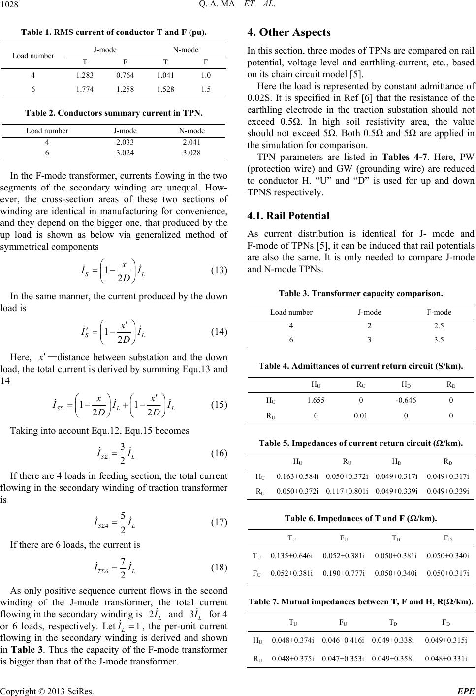
Table 1. RMS current of conductor T and F (pu).
J-mode N-mode
Load number T F T F
4 1.283 0.764 1.041 1.0
6 1.774 1.258 1.528 1.5
Table 2. Conductors summary current in TPN.
Load number J-mode N-mode
4 2.033 2.041
6 3.024 3.028
In the F-mode transformer, currents flowing in the two
segments of the secondary winding are unequal. How-
ever, the cross-section areas of these two sections of
winding are identical in manufacturing for convenience,
and they depend on the bigger one, that produced by the
up load is shown as below via generalized method of
symmetrical components
12
S
xL
I
D
(13)
In the same manner, the current produced by the down
load is
12
S
xL
I
D
(14)
Here,
—distance between substation and the down
load, the total current is derived by summing Equ.13 and
14
11
22
SL
xx
L
I
DD
I
(15)
Taking into account Equ.12, Equ.15 becomes
3
2
SL
I
(16)
If there are 4 loads in feeding section, the total current
flowing in the secondary winding of traction transformer
is
4
5
2
SL
I
(17)
If there are 6 loads, the current is
6
7
2
TL
I
(18)
As only positive sequence current flows in the second
winding of the J-mode transformer, the total current
flowing in the secondary winding is 2
and 3
for 4
or 6 loads, respectively. Let, the per-unit current
flowing in the secondary winding is derived and shown
in Table 3. Thus the capacity of the F-mode transformer
is bigger than that of the J-mode transformer.
1
L
I
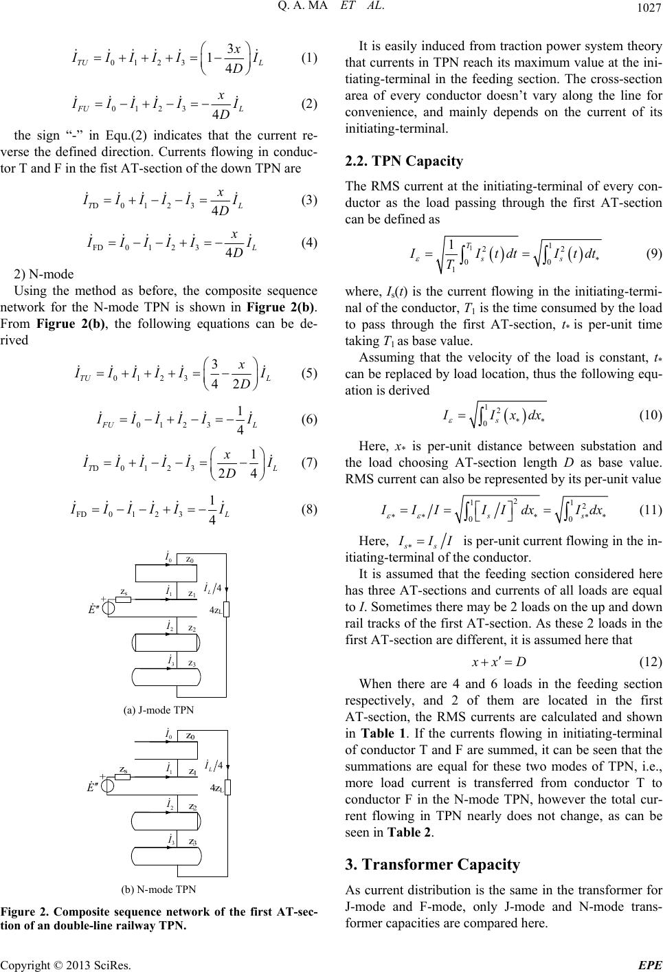
4. Other Aspects
In this section, three modes of TPNs are compared on rail
potential, voltage level and earthling-current, etc., based
on its chain circuit model [5].
Here the load is represented by constant admittance of
0.02S. It is specified in Ref [6] that the resistance of the
earthling electrode in the traction substation should not
exceed 0.5Ω. In high soil resistivity area, the value
should not exceed 5Ω. Both 0.5Ω and 5Ω are applied in
the simulation for comparison.
TPN parameters are listed in Tables 4-7. Here, PW
(protection wire) and GW (grounding wire) are reduced
to conductor H. “U” and “D” is used for up and down
TPNS respectively.
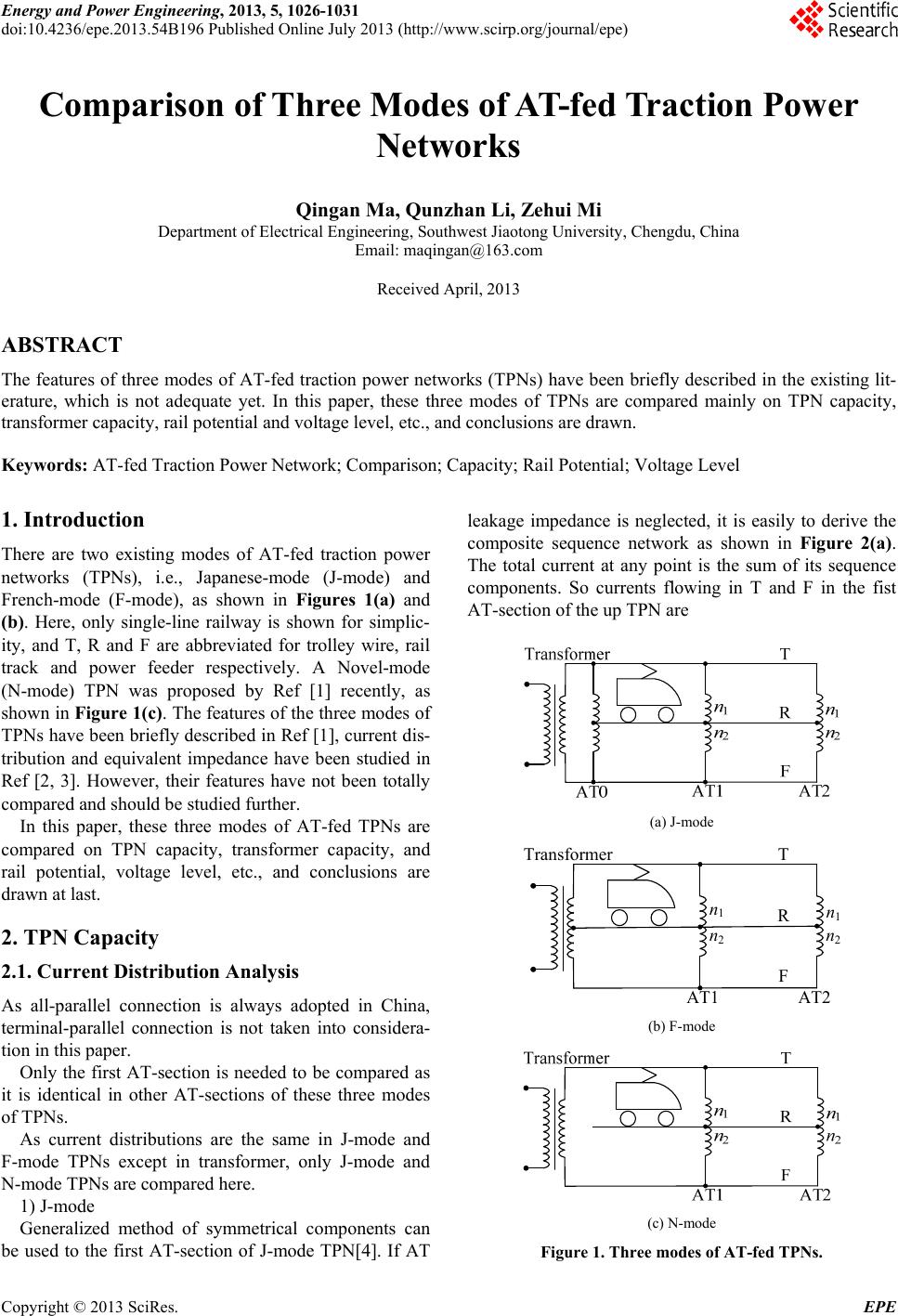
4.1. Rail Potential
As current distribution is identical for J- mode and
F-mode of TPNs [5], it can be induced that rail potentials
are also the same. It is only needed to compare J-mode
and N-mode TPNs.
Table 3. Transformer capacity comparison.
Load number J-mode F-mode
4 2 2.5
6 3 3.5
Table 4. Admittances of current return circuit (S/km).
H
U R
U H
D R
D
HU 1.655 0 -0.646 0
RU 0 0.01 0 0
Table 5. Impedances of current return circuit (Ω/km).
H
U R
U H
D R
D
HU 0.163+0.584i0.050+0.372i 0.049+0.317i 0.049+0.317i
RU 0.050+0.372i0.117+0.801i 0.049+0.339i 0.049+0.339i
Table 6. Impedances of T and F (Ω/km).
T
U F
U T
D F
D
TU0.135+0.646i 0.052+0.381i 0.050+0.381i 0.050+0.340i
FU0.052+0.381i 0.190+0.777i 0.050+0.340i 0.050+0.317i
Table 7. Mutual impedances between T, F and H, R(Ω/km).
T
U F
U T
D F
D
HU0.048+0.374i 0.046+0.416i 0.049+0.338i 0.049+0.315i
RU0.048+0.375i 0.047+0.353i 0.049+0.358i 0.048+0.331i
Copyright © 2013 SciRes. EPE