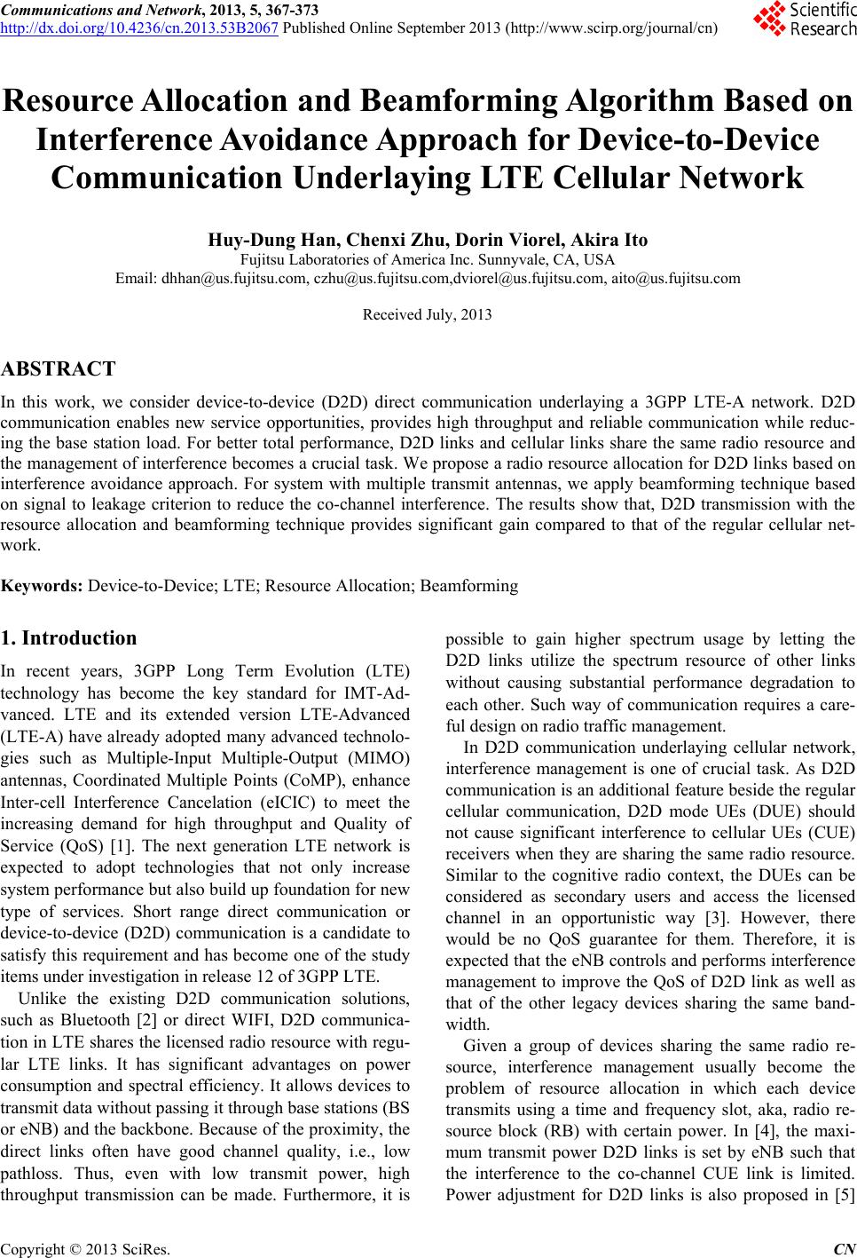
 Communications and Network, 2013, 5, 367-373 http://dx.doi.org/10.4236/cn.2013.53B2067 Published Online September 2013 (http://www.scirp.org/journal/cn) Resource Allocation and Beamforming Algorithm Based on Interference Avoidance Approach for Device-to-Device Communication Underlaying LTE Cellular Network Huy-Dung Han, Chenxi Zhu, Dorin Viorel, Akira Ito Fujitsu Laboratories of America Inc. Sunnyvale, CA, USA Email: dhhan@us.fujitsu.com, czhu@us.fujitsu.com,dviorel@us.fujitsu.com, aito@us.fujitsu.com Received July, 2013 ABSTRACT In this work, we consider device-to-device (D2D) direct communication underlaying a 3GPP LTE-A network. D2D communication enables new service opportunities, provides high throughput and reliable communication while reduc- ing the base station load. For better total performance, D2D links and cellular links share the same radio resource and the management of interference becomes a crucial task. We propose a radio resource allocation for D2D links based on interference avoidance approach. For system with multiple transmit antennas, we apply beamforming technique based on signal to leakage criterion to reduce the co-channel interference. The results show that, D2D transmission with the resource allocation and beamforming technique provides significant gain compared to that of the regular cellular net- work. Keywords: Device-to-Device; LTE; Resource Allocation; Beamforming 1. Introduction In recent years, 3GPP Long Term Evolution (LTE) technology has become the key standard for IMT-Ad- vanced. LTE and its extended version LTE-Advanced (LTE-A) have already adopted many advanced technolo- gies such as Multiple-Input Multiple-Output (MIMO) antennas, Coordinated Multiple Points (CoMP), enhance Inter-cell Interference Cancelation (eICIC) to meet the increasing demand for high throughput and Quality of Service (QoS) [1]. The next generation LTE network is expected to adopt technologies that not only increase system performance but also b uild up foundatio n for new type of services. Short range direct communication or device-to-device (D2D) communication is a candidate to satisfy this requirement and has become one of the study items under investigation in release 12 of 3GPP LTE. Unlike the existing D2D communication solutions, such as Bluetooth [2] or direct WIFI, D2D communica- tion in LTE shares the licensed radio resource with regu- lar LTE links. It has significant advantages on power consumption and spectral efficiency. It allows devices to transmit data without passing it through base stations (BS or eNB) and the backbone. Because of the proximity, the direct links often have good channel quality, i.e., low pathloss. Thus, even with low transmit power, high throughput transmission can be made. Furthermore, it is possible to gain higher spectrum usage by letting the D2D links utilize the spectrum resource of other links without causing substantial performance degradation to each other. Such way of communication requires a care- ful design on radi o t raf fi c m anagement. In D2D communication underlaying cellular network, interference management is one of crucial task. As D2D communication is an ad ditional feature besid e the regular cellular communication, D2D mode UEs (DUE) should not cause significant interference to cellular UEs (CUE) receivers when they are sharing the same radio resource. Similar to the cognitive radio context, the DUEs can be considered as secondary users and access the licensed channel in an opportunistic way [3]. However, there would be no QoS guarantee for them. Therefore, it is expected that the eNB controls and performs interference management to improve the QoS of D2D link as well as that of the other legacy devices sharing the same band- width. Given a group of devices sharing the same radio re- source, interference management usually become the problem of resource allocation in which each device transmits using a time and frequency slot, aka, radio re- source block (RB) with certain power. In [4], the maxi- mum transmit power D2D links is set by eNB such that the interference to the co-channel CUE link is limited. Power adjustment for D2D links is also proposed in [5] C opyright © 2013 SciRes. CN  H.-D. HAN ET AL. 368 to dynamically reduce the interference. In [6], the power level is set to optimize the transmission sum rate of both CUEs and DUEs. Nevertheless, the power control should be jointly considered with reso urce allocation/scheduling to minimize the potential critical interference [7]. Be- sides, under LTE scenario, the spectrum resource alloca- tion/scheduling rate is faster than that of the power ad- justment; thereby, the instanta n eou s sign al to interference and noise (SINR) for each UE depends more on sched- uling. Therefore, channel/interference aware scheduling algorithms can be more beneficial for the system per- formance. In [8], the area of possible D2D transmission is calculated by pathloss threshold. However, the area modeling is over simplified leading to the sub-optimal performance. In this work, we investigate an interference avoidance scheduling algorithm for D2D links. Given a schedule for CUEs, each D2D link is paired up with a CUE link and sharing the scheduled RBG by a pairing algorithm. The D2D pairs are allocated such that the interference at each involved device is below a threshold. For the D2D pairs violating the requirement, a default spectrum resource is provided so that they still can transmit with best effort basis. For multiple transmit antennas system, we apply a beamforming based on signal to interference and noise (SLNR) metric [9,10] to further reduce the interference. The results show that, with the pairing algorithm, the co-channel interference between D2D pairs and the CUE uplink is mitigated and the system throughput is opti- mized. 2. System Model We consider D2D links sharing uplink bandwidth with the regular CUEs. The total uplink frequency resource for data is assumed to be divided into N resource block groups (RBG)1. At a given time slot t, the RBG can be indexed as (, where )tf {1,.., } N . There are c uplink CUEs and d D2D pairs sharing this radio re- source. If D2D links and a CUE uplink sharing RBG , co-channel interference degrades the performance of both links. Figure 1 represents channel model where D2D links j, k and an uplink CUE i transmit in the same RBG. Here, D2D pair k consists of a DUE transmitter (DUE-T) k and a DUE receiver (DUE-R) k. For the sake of simplicity, the RBG index indicator is omitted. The channel and interference include the following compo- nents: L L (, )tf () c i: the channel matrix fro m CUE i to the eNB. () cd k: the channel matrix from DUE-T k to the eNB. (,) dd kj: the channel matrix from DUE-T j to DUE-R k. () d k: the channel matrix from DUE-T k to DUE-R k. (,) dc ki: the channel matrix from the CUE i to DUE-R k. If multiple antennas are equipped at the transmitter, beamforming technique can be used to improve the SINR. We define the precoding matrices for CUE i and for DUE-T k as Wand W respectively. In practice, the precoding matrices belong to a codebook . () ci () dk, The performance of the system depends on the co- channel interference causing by the devices. The intra- cell co-channel interference measured at eNB is 2 ()( )( ) i ccdd kD iHkWk (1) where i is the index set of the D2D links sharing the bandwidth with CUE i. The SINR for uplink CUE i can be calculated as 2 0, () () () () () cc ccc iW i iNiIi (2) where 0, are the noise power plus the interference from other cells for the link i. Similarly, the interference measured at DUE-R k and its SINR are calculated as, respectively: () c Ni 22 , ()()()(,)() , i ddcc ddd jDj k kHkWi HkjWj (3) 2 0, () () () () () dd ddd kW k kNkIk (4) where 0, are the noise power plus the interference from other cells for the D2D link . () d Nk k The problem of radio resource management at eNB is to decide the sets i for all i together with precoding matrices such that the optimum sum throughput is achieved over a long time period as: Figure 1. Channel model for D2D pairs sharing bandwidth with an uplink CUE. The solid lines represent the direct links. The dot lines represent co-channel interference. 1The term resource block group is taken from LTE specification [1] since we are using LTE scenarios for simulation. Copyright © 2013 SciRes. CN  H.-D. HAN ET AL. 369 () () () () () 11 ,(),() Maximizing( )() c tt t c i d d LL tt cd ti k WiWk Ti Tk (5) where , are the throughput of CUE i and DUE k at time t. The throughputs can be defined using Shannon capacity formula [11] as () () t c Ti () () dt Ti 2 log 1B with B is the bandwidth of a RBG and is the SINRs defined in (2), (4). Th e time index t is added to to represent their changes over time. ,( ic Wi),() d Wk The problem in (5) can be classified as a NP-hard as it can be reduced to a si mpler, but still NP-hard, scheduling algorithm [12]. In [12], a proportional fair algorithm can be performed to optimize the total throughput over time while allowing all the UEs receive at least a minimal QoS. Such algorithms usually depends on the assumption that the interference is small and relative unchanged, i.e., () c and () d are negligible. When there are multiple devices scheduled on one RBG, this assumption no longer holds. Therefore, new designs considering inter- ference after resource allocation are required. The instantaneous rate of a UE depends on its relative location with eNB, the varying channel and the co- channel interference. Compare to the transmission rate of CUEs in traditional cellular system, the instantaneous rate of CUEs in the presence of D2D communication depends more on the intra-cell co-channel interference. Hence, for a group of a CUE and DUEs sharing the same RBG, the instantaneous interference depends on the re- source assignment. Therefore, the task of resource allo- cation for UEs sharing resource is very different from the one for uplink only. In section 3, we propose a resource allocation mechanism for D2D pair sharing bandwidth with an uplink CUE, called pairing algorithm. Based on interference avoidance approach, the pairing algorithm allows many D2D links reuse the uplink radio resource while maintaining the uplink performance. The problem in (5) considers resource allocation and precoding matrices to optimize the performance and, thereby, hard to solve. Therefore, we separate the two processes by applying the pairing algorithm first; then, given the resource assignment, we determine the opti- mum beamforming. In section 5, we introduce a beam- forming technique to reduce the in-cell co-channel inter- ference and improve throughput performance. 3. Pairing Algorithm Based on Interference Threshold and Default RBG As the general problem is NP-hard, we propose a heuris- tic algorithm whose assu mption is that the CUE has been scheduled without knowledge of DUE channels. The assumption is based on two folds: CUEs requires better QoS protection as the DUEs always have better channel due to their proximity; CUEs should have higher pri- orityas D2D communication is an additional feature in cellular network. With this assumption, we can reduce the general problem to the pairing algorithm whose task is to assign a group of DUEs to pair with a CUE and share its scheduled resource. The pairing algorithm also assumes that the signal strength of D2D links is often very high and eliminating the co-channel interference is essential. Therefore, the pairing process is based on the thresholds of interference. A CUE link and a D2D link are paired to transmit on th e same RBG only when the interference satisfies thresh- olds conditions for both receivers. There are several ex- isting interference avoidance algorithms [13] that work well when the number of D2D pairs is not too large. However, if the number of D2D pairs is large, only few D2D pairs can share resource this way. In our pairing algorithm, we propose that if the D2D pair cannot share the resource with the CUE, they still can transmit on the default resource with limited rate. With the default re- source, all of D2D pairs can transmit at the same time and the total throughput is increase. In the rest of the paper, without loss of generality, we assume that the RBG 1 is used as the default RBG. The candidates, in- cluding CUE i and DUE k are paired up only the inter- ference at all involved receivers are below the thresholds: () ci for CUEs and () dk for DUEs. Otherwise, the DUE will be assigned to transmit on the default RBG. The complete pairing algorithm including the interfer- ence calculation is described in the following pseudo code: k Inputs: : set of CUEs index that already scheduled on RBG. N N : set of DUEs need to be scheduled. RBG 1: default RBG. CUE 1: CUE that scheduled on RBG 1. Outputs: i Begin: : set of DUE indices paired with CUE i. i for all i . For each k For each i Calculate interference levels )( c i and using equations (1),(3). )( d Ik If )( cc )( ii and )( dd )( ii then Pair up DUE link i and CUE link i: {} ii k End if End For If D2D link k is not paired with any CUE in Pair up D2D link k and CUE 1: 11 {}k End If End For End. The pairing algorithm calculates the interference by measuring the signals power from all other interferer. Copyright © 2013 SciRes. CN  H.-D. HAN ET AL. 370 Therefore, only the amplitude of signal is needed. 4. The Choice of Interference Thresholds The interference thresholds can be calculated from the target SINRs. As the expression derivations for CUEs and DUEs are similar, we only describe the CUE case. The pairing algorithm should pick the channel such that the average SINR is larger than the target SINR 0, () ci as 2 0, 0, () ()(). () () cc c cc HiWi Ei Ni Ii (6) Considering the signal, interference and noise are in- dependent, we arrive at 2 0, 0. ()() () () . () cc cc c EHiWi IiN i i (7) We can set (i) c to be the right hand side of (7). If the devices is equipped with single transmit antenna can be omitted. Applying the pairing algorithm with this threshold guarantees that the target SINR is met. () c Wi For multiple transmit antennas case, the threshold conditions may not be guaranteed as the desired signal and the interference depend on beamforming. One can set the interference threshold corresponding to the mini- mum signal strength. However, this value may be nega- tive. Therefore, we can set the threshold as the average value over all possibilities o f the precoding matrix as: || 2 () 10, 0. 1() || () () () n c n c c EHiW i i c N i (8) where is the value of -th entry of the codebook and is the cardinality of the codebook. Although, there is no guarantee that the interference is always be- low the threshold, we still can choose the precoding ma- trix of the interferer so that the interference is below the threshold most of the time. In the next section, we dis- cuss several precoding matrix selection algorithms. ()n W || n 5. Beamforming Strategy Based on SLNR Criterion Given the spectrum allocation, the optimum beamform- ing should consider all beamformers at the same time to maximize the sum throughput of the CUE and DUEs as in (5). However, the complexity of this app roach is high as it is proportional to the exponential of number of devices. Furthermore, because the SINRs of CUE and DUEs are coupled, this optimization problem has no closed form solution. Therefore, we consider an alternative beam- forming technique based on SLNR criterion. Using this criterion, the precoding matrix can be determined locally and independent from other links. The principle is to find the precoding matrix that achieving the balance of maximizing the received signal strength at the intended receiver and minimizing the interference at the others. As the result, the throughput can be optimized. The SLNR for CUE is defined as: i 2 2 0, () () () () () i cc c ccdc k HiWi iNHiWi (9) and the SLNR for DUE i k is 2 22 0, , () () () . () ()(,) () i dd d ddcddd d llk HkWk kNHkWk HlkWk (10) The optimum solution can be calculated using Rayleigh-Ritz quotient[14]. Under predefined codebook, the optimum precoding matrix can be found by trying all possibilities as ()argmax(),( )argmax( ) ccd Wii Wkk d (11) For each transmitter, th e selection of precoding matrix based on SLNR requires channel information between the transmitter and the involved receivers. If the precod- ing matrix is calculated at eNB, all the channel informa- tion is transmitted to the eNB. On the other hand, if the precoding matrix is calculated at the transmitter, for ex- ample, DUE-T k, the corresponding channels, (,) cd ik , (,) dd jk , are reported to the DUE-T. Nevertheless, under Time-Division Duplex (TDD) system, the recip- rocity of channels can be exploited such that the channel from a DUE-T to the corresponding DUE-R and eNB is already available at the DUE-T. Therefore, in TDD system, the SLNR approach re- quires less channel information exchange and further reduces the control overhead. 6. Numerical Results In this section, we evaluate the performance of CUEs and DUEs using aforementioned algorithms by a system level simulator (SLS). We consider uplink synchronized LTE cellular net- work with Urban Microcell (UMi) scenario with UE moving speed of 3km/h as defined in model 1 of [16]. There are 7 eNBs equal space located with distance of 500 m and each divides into 3 cells using 120 degree vertical antennas. The network is assumed to operate on a 10 MHz band with 2GHz carrier. The band is divided into 9 RBGs. Each cell is assigned 20 CUEs and 10 DUEs. The location of CUEs and DUE-T are uniformly random generated over the area of network. The DUE-Rs Copyright © 2013 SciRes. CN  H.-D. HAN ET AL. 371 are uniformly random located around the correspondent DUE-Ts with maximum distancemax . The UE- eNB pathloss model in dB is defined in [16] as 30dm dkm dkm 10 128.137.6log( []) UE eNB L (12) and UE-UE pathloss model is defined in [17] as 10 14840log( []). UE UE L (13) We assume open loop power control with complete pathloss compensation. The average receive signal power is dBm for CUEs and 10080 dBm for DUEs. As- sumptions on the network includes full buffer traffic model, proportional fair (PF) algorithm for scheduling the CUEs and ideal channel estimation with MMSE re- ceiver. The throughput is measured by the number of bits successfully transmitted using certain Modulation and Coding Scheme (MCS) defined in [15] over the simu- lated time. The success of transmission is signaled by ACK/NAK assuming a Block Error Rate of 10%, the HARQ is incremental redundancy (IR) with maximum 3 retransmissions. We study the proposed algorithms under SIMO (12 ) MIMO () channel model. To see the benefits of the algorithms, we compare the following setups for SLS: 22 Only uplink CUEs transmit (marked as “CUE only”). Each D2D pair is assigned with a uniformly random RBG (marked as “Random RBG”). The D2D pairs use the default RBG only (marked as “Default RBG”). The DUE-Ts is assigned using the aforementioned pairing algorithm. There could be more than one D2D pairs transmitting on the same RBG. The interference threshold for CUEs is 100dBm and for DUEs is 90dBm (marked as “Pairing”). We first examine the pairing algorithm for system with one transmit antenna. Figure 2 and Figure 3 show the CUE throughput and DUE throughput cumulative distri- bution function (CDF), respectively. Compar ing “Default RBG” and “CUE only” setups, we see that the use of the default RBG for D2D transmission does not affect CUE throughput significantly. Instead, enabling of D2D transmission has improved the total cell throughput. The transmission with random RBG allocation does not take in to account the CUEs' QoS protection; th ereby, the CUE throughput degrades compare to the “Default RBG” case. On the other hand, the D2D throughput has improve as the D2D links do not need to share only one RBG. The pairing algorithm takes into account the possible interference to the other devices. Therefore, we can see that, the CUE throughput does not degrade compared to the case that D2D pairs transmittin g on the default RBG. The DUE-Ts, whenever possible, transmit on the RBG other than the default one. Hence, the DUE throughput improves and is comparable with that of random RBG case. Table 1 shows the average cell throughput of each test case. The cell throughpu t is measu r ed by summing all th e CUEs and DUEs throughput of the cell and averaged over cells. We can see that the D2D transmission im- prove the cell throughput by 25% (Random RBG) and up to 90% (using pairing algorithm). 02004006008001000 1200140016001800200 0 0.1 0.2 0.3 0.4 0.5 0.6 0.7 0.8 0.9 1 Throughput (k bps ) CDF Default RB G Random RB G Pairing CUE onl y Figure 2. CUE throughput CDF (SIMO case). 05001000 15002000 2500 3000 35004000 0 0.1 0.2 0.3 0.4 0.5 0.6 0.7 0.8 0.9 1 Throughput (kbp s ) CDF Default RBG Random RB G Pairing Figure 3. DUE throughput CDF (SIMO case). Table 1. The average throughput of cells and UEs. Average cell throughput (Mbps) SIMO M IMO CUE only 11.6 14.73 Default RBG 16.3 28.6 Random RBG 14.56 23.3 Pairing 20.7 35.9 Copyright © 2013 SciRes. CN 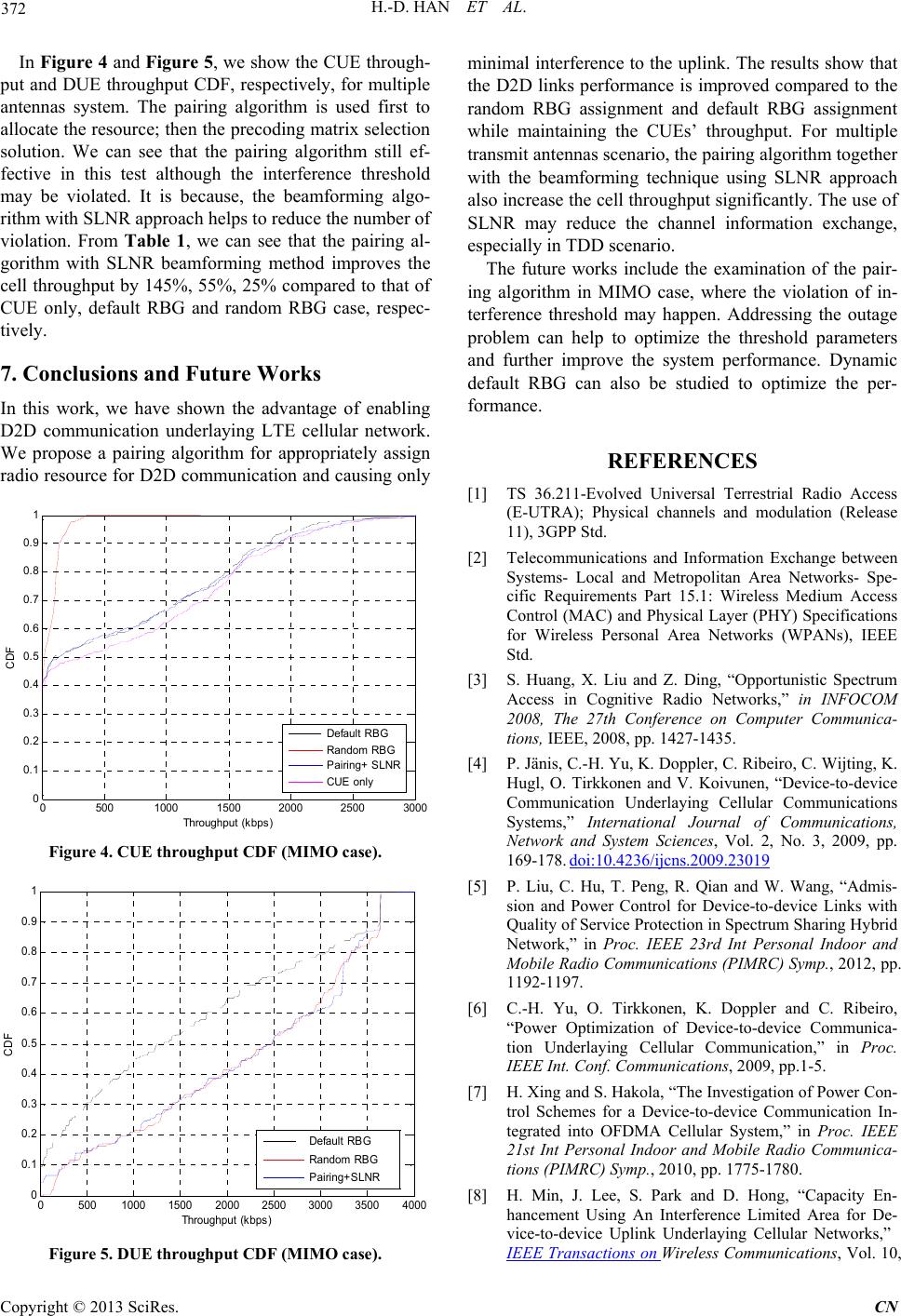 H.-D. HAN ET AL. 372 In Figure 4 and Figure 5, we show the CUE through- put and DUE throughput CDF, respectively, for multiple antennas system. The pairing algorithm is used first to allocate the resource; then the precoding matrix selection solution. We can see that the pairing algorithm still ef- fective in this test although the interference threshold may be violated. It is because, the beamforming algo- rithm with SLNR approach helps to reduce the number of violation. From Table 1, we can see that the pairing al- gorithm with SLNR beamforming method improves the cell throughput by 145%, 55%, 25% compared to that of CUE only, default RBG and random RBG case, respec- tively. 7. Conclusions and Future Works In this work, we have shown the advantage of enabling D2D communication underlaying LTE cellular network. We propose a pairing algorithm for appropriately assign radio resource for D2D communication and causing only 0500 10001500 2000 25003000 0 0. 1 0. 2 0. 3 0. 4 0. 5 0. 6 0. 7 0. 8 0. 9 1 Throughput (k bps) CDF Default RB G Random RB G Pairing+ SLNR CUE o nl y Figure 4. CUE throughput CD F (MIMO case). 05001000 15002000 2500 3000 35004000 0 0.1 0.2 0.3 0.4 0.5 0.6 0.7 0.8 0.9 1 Throughput (k bps) CDF Default RB G Random RBG Pairing+SLNR Figure 5. DUE throughput CD F (MIMO case). minimal interference to the uplink. The results sh ow that the D2D links performance is improved compared to the random RBG assignment and default RBG assignment while maintaining the CUEs’ throughput. For multiple transmit antennas scenario, the pairing algorith m togeth er with the beamforming technique using SLNR approach also increase the cell throughp ut significantly. The use of SLNR may reduce the channel information exchange, especially in TDD scenario. The future works include the examination of the pair- ing algorithm in MIMO case, where the violation of in- terference threshold may happen. Addressing the outage problem can help to optimize the threshold parameters and further improve the system performance. Dynamic default RBG can also be studied to optimize the per- formance. REFERENCES [1] TS 36.211-Evolved Universal Terrestrial Radio Access (E-UTRA); Physical channels and modulation (Release 11), 3GPP Std. [2] Telecommunications and Information Exchange between Systems- Local and Metropolitan Area Networks- Spe- cific Requirements Part 15.1: Wireless Medium Access Control (MAC) and Physical Layer (PHY) Specifications for Wireless Personal Area Networks (WPANs), IEEE Std. [3] S. Huang, X. Liu and Z. Ding, “Opportunistic Spectrum Access in Cognitive Radio Networks,” in INFOCOM 2008, The 27th Conference on Computer Communica- tions, IEEE, 2008, pp. 1427-1435. [4] P. Jänis, C.-H. Yu, K. Doppler, C. Ribeiro, C. Wijting, K. Hugl, O. Tirkkonen and V. Koivunen, “Device-to-device Communication Underlaying Cellular Communications Systems,” International Journal of Communications, Network and System Sciences, Vol. 2, No. 3, 2009, pp. 169-178. doi:10.4236/ijcns.2009.23019 [5] P. Liu, C. Hu, T. Peng, R. Qian and W. Wang, “Admis- sion and Power Control for Device-to-device Links with Quality of Service Protection in Spectrum Sharing Hybrid Network,” in Proc. IEEE 23rd Int Personal Indoor and Mobile Radio Communications (PIMRC) Symp., 2012, pp. 1192-1197. [6] C.-H. Yu, O. Tirkkonen, K. Doppler and C. Ribeiro, “Power Optimization of Device-to-device Communica- tion Underlaying Cellular Communication,” in Proc. IEEE Int. Conf. Communications, 2009, pp.1-5. [7] H. Xing and S. Hakola, “The Investigation of Power Con- trol Schemes for a Device-to-device Communication In- tegrated into OFDMA Cellular System,” in Proc. IEEE 21st Int Personal Indoor and Mobile Radio Communica- tions (PIMRC) Symp., 2010, pp. 1775-1780. [8] H. Min, J. Lee, S. Park and D. Hong, “Capacity En- hancement Using An Interference Limited Area for De- vice-to-device Uplink Underlaying Cellular Networks,” IEEE Transactions on Wireless Communications, Vol. 10, Copyright © 2013 SciRes. CN 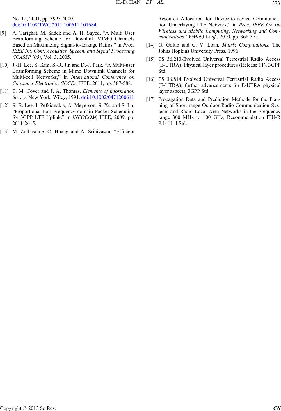 H.-D. HAN ET AL. Copyright © 2013 SciRes. CN 373 No. 12, 2001, pp. 3995-4000. doi:10.1109/TWC.2011.100611.101684 [9] A. Tarighat, M. Sadek and A. H. Sayed, “A Multi User Beamforming Scheme for Downlink MIMO Channels Based on Maximizing Signal-to-leakage Ratios,” in Proc. IEEE Int. Conf. Acoustics, Speech, and Signal Processing (ICASSP ’05), Vol. 3, 2005. [10] J.-H. Lee, S. Kim, S.-R. Jin and D.-J. Park, “A Multi-user Beamforming Scheme in Mimo Downlink Channels for Multi-cell Networks,” in International Conference on Consumer Electronics (ICCE), IEEE, 2011, pp. 587-588. [11] T. M. Cover and J. A. Thomas, Elements of information theory. New York, Wiley, 1991. doi:10.1002/0471200611 [12] S.-B. Lee, I. Pefkianakis, A. Meyerson, S. Xu and S. Lu, “Proportional Fair Frequency-domain Packet Scheduling for 3GPP LTE Uplink,” in INFOCOM, IEEE, 2009, pp. 2611-2615. [13] M. Zulhasnine, C. Huang and A. Srinivasan, “Efficient Resource Allocation for Device-to-device Communica- tion Underlaying LTE Network,” in Proc. IEEE 6th Int Wireless and Mobile Computing, Networking and Com- munications (WiMob) Conf., 2010, pp. 368-375. [14] G. Golub and C. V. Loan, Matrix Computations. The Johns Hopkins University Press, 1996. [15] TS 36.213-Evolved Universal Terrestrial Radio Access (E-UTRA); Physical layer procedures (Release 11), 3GPP Std. [16] TS 36.814 Evolved Universal Terrestrial Radio Access (E-UTRA); further advancements for E-UTRA physical layer aspect s, 3GPP Std. [17] Propagation Data and Prediction Methods for the Plan- ning of Short-range Outdoor Radio Communication Sys- tems and Radio Local Area Networks in the Frequency range 300 MHz to 100 GHz, Recommendation ITU-R P.1411-4 Std.
|