 Communications and Network, 2013, 5, 260-265 http://dx.doi.org/10.4236/cn.2013.53B2047 Published Online September 2013 (http://www.scirp.org/journal/cn) Performance Analysis of Optical W ir eless Communication System Employing Neuro-Fuzzy Based Spot-Diffusing Techniques Shamim Al Mamun1, M. Shamim Kaiser1, Muhammad R Ahmed2, Md. Shafiqul Islam3, Md. Imdadul Islam4 1Institute of Information Technology, Jahangirnagar University, Savar, Bangladesh 2School of Information Technology & Engineering, University of Canberra, Australia 3Department of Physics, Jahangirnagar University, Savar, Bangladesh 4Department of Computer Science of Engineering, Jahangirnagar University, Savar, Bangladesh Email: Shamim@juniv.edu, mskaiser@juniv.edu, muhammad.ahmed@canberra.edu.au, shafiq1190@yahoo.com, imdad@juniv.edu Received June, 2013 ABSTRACT The spot-diffusing technique provides better performance compared to conventional diffuse system for indoor opti- cal-wireless communication (OWC) system. In this paper, the performance of an OW spot-diffusing communication system using Neuro-Fuzzy (NF) adaptive multi-beam transmitter configuration has been proposed. The multi-beam transmitter generates multiple spots pointed in different directions, hence, forming a matr ix of diffusing spots based on position of the receiver and receiver mobility. Regardless of the position of the transmitter and receiver, NF controller target the spots adaptively at the best locations and allocates optimal power to the spots and beam angle are adapted in order to achieve better signal-to-noise plus interference ratio (SNIR). Maximum ratio combining (MRC) is used in the imaging receiver. The proposed OW spot-diffusing communication system is compared with other spot-beam diffusion methods proposed in literature. Performance evaluation revels that the proposed NF based OW spot-diffusing commu- nication system outperforms other spot-beam diffusion methods. Keywords: Optical-wireless Communication; Spot Diffusion Techni que; Neuro-fuzzy; Imaging Receiver; Adaptive Power Alloca t ion 1. Introduction With the increasing development of ultra-broadband wireless application the radio frequency (RF) spectrum became congested and scare resources. Thus optical wireless communication (OWC) has drawn considerable attention to the researchers. OWC for indoor application was first proposed by Gfeller and Baps t [1]. In number of applications where higher data throughputs is more of requirement than the mobility, transmission lin k based on optical wireless would be one of the best options as out- lined in [2-5]. The performance of OW systems depends on the propagation and type of system used. The basic system types fall into diffuse or line of sight (LOS) sys- tems. In LOS systems, high data rates in the order of Gbit/s can be achieved [6], but the system is vulnerable to blockage/shadowing because of its directionality. In a diffuse OW system, several paths from source to receiver exist, which makes the system robust to blockage/ shadowing. However, the pa th losses are high and multi- paths create inter-symbol interference (ISI) which limits the achievable data rate [7,8]. There are several advan- tages of OWC over traditional RF systems, these are: an abundant free spectrum, extremely high communication speed is possible by all network, does not interfere with the over congested RF spectrum. But limitations are: a beam is short ranged, may be harmful for eye. The first limitation can be overcome by wavelength reuse tech- nique, whereas eye safety can be ensured by maximum transmit power. It can be classified as line of sight (LOS) and diffuse system. Many researchers have considered diffuse systems for indoor applications it offers robust link and overcomes the problem of shadowing [7], does not require transmitter-receiver alignment and uses the wall or ceiling for multi path reflection [8]. The multi- path reflections increases delay spread or inter-symbol interference. Ambient light such as florescent, incandes- cent light and Compact Florescent Lamp (CFLs) pro- duces channel noise which reduces signal-to-noise plus C opyright © 2013 SciRes. CN  S. Al MAMUN ET AL. 261 interference rat o (SNIR). In order to improve the system performance several spot diffusion configuration using multi beam transmitter have been proposed [9]. Multi beam transmitter is place in center of the room and pointed upward. A multi-spot pattern have been gener- ated, illuminated multiple small areas in the ceiling and then reflected multiple spot have been received by re- ceivers. In [10], to improve the bandwidth, reduce the effect of inter-symbol interference, and increase the sig- nal to noise ratio (SNR) when the transmitter operates at a higher data rate under the impact of multipath disper- sion, background noise, and mobility in conjunction with an imaging receiver. It proposed different line streaming multi-beam spot diffusion (LSMS) model to gain about 32.3 dB SNR at worst communication path. But the multi path dispersion reduces the performances due to trans- mitter power and can be improve using power adaptive system by [9]. User mobility is very important aspect of wireless communication especially with today’s hand hold devices. As the user device can mobilize with the room then power adaptation will be a great solution to get higher SNR. In this aspect [12] propose a genetic algorithm for multi spot diffuse system in indoor wireless communication. But it is noted from different research that if the diffuse system has a predefined spot for a room and use an adaptive power allocation for beam using calculation of delay spread then it can improve the per- formance of the OWC. Neural network and Adaptive Linear Equalizers can be a solution in this case for adap- tive power distribution. [12] Presents a comparative study of two equalizers, the adaptive linear and the neu- ral equalizer for indoor optical wireless (OW) links using OOK modulation technique to reduce ISI effect. This paper introduce adaptive neuro-fuzzy interference system (ANFIS) for selecting spot beam matrix for a room and also distribute power allocation by calculating delay spread in considering Doppler shift effect of the mobile devices. The paper is organized as follows: the system model is presented in section 2; power allocation algo- rithm is explained in section 3; Section 4 presents dis- cussion and results. The concluding remarks and future work is included in section 5. 2. Proposed System Model Consider an empty room with floor dimensions of 8×4 m2 and ceiling height of 3m as shown in Figure 1. The reflection coefficient of the ceiling is considered to be 0.8. There are eight spot lights on the ceiling. In the Fig- ure, is the elevation angle, is the azimuth angle, d = 8, w = 4 and h = 3, x0 and x are the position of the imag- ing receiver and v is the velocity. Neuro-Fuzzy (NF) adaptive multi-beam transmitter is located at the center of the room whereas an imaging receiver is placed at x0 = (1, 1, 0.5). The transmitter generates multi spot beam matrix on the ceiling where beam power and beam angle ( , x R ) are adapted and the reflected beams are received by the imaging receiver. The transmitter learns receiver position, mobility through the low rate diffuse channel. At low data rate, the beam maintains the fixed power. 2.1. Signal to Noise Plus Interference Ratio In indoor optical-wireless communication, the ambient light affects signal-to-noise-plus interference (SNIR) at the receiver. Many researchers have considered intensity modulation with direct detection (IM/DD) as most viable approximation. The received signal, denoted by y(t), can be expressed as ()()(, ,)(, ,)I(, ,)ytt htntt (1) where, R is the receiver responsively , x(t) is the instan- taneous optical transmitted power, (,, )ht (,, )nt is the im- pulse response of the OW channel, is the am- bient light noise, (,, )It is the instantaneous inter- ference pow er. The SNIR, denoted by , of the received signal can be calculated by [9] 10 22 2 10 () () ii si ii RPPh (2) where, Ps1 and Ps0 are the optical power associated with the binary 1 and binary 0 respectively, s1 are s0 are the shot noise variation component with Ps1 and Ps0 re- spectively. 2.2. Adaptive Power Allocation The achievable data transmission rate, denoted by b, of the OWC system is given by 10 22 22 110 () 1log 1() ii Mssi iii RPPh M b (3) The optimization problem and constraint of the power allocation can be written as, d h w v 0 Figure 1. System Model for OWC based on spot-diffusing technique. Copyright © 2013 SciRes. CN  S. Al MAMUN ET AL. 262 max b (4) 1 .. J j j tP P (5) where P is the average power. We can use the La- grange multiplier method to analyze the above optimiza- tion problem and the Lagrangian function is defined as 1 J jj j LbP P (6) where, µj is the Lagrange multiplier. After solving the Eqn. (6), we can write 1 1 1 J ji ji Ph PCh (7) 1 = max(C),0 i h (8) 2.3. Delay Spread The delay spread of an impulse is expressed as rms value by, 22 2 (t ) i r P DP r (9) where, and is the delay time and is the re- ceived power i tr P 2.4. Doppler Shift Light waves require no medium and being able to travel even through vacuum. Let v is the relative velocity between transmitter and receiver, the proper frequency of the transmitted information signal from the optical transmitter is 0 . Let f is the frequency of the received signal accepted by the moving receiver with a velocity v, then 01 1 ff (10) where, /, vcc is the speed of light. For low speed, i.e. 1 , the above eqn. (10) is reduced to 1 2 0 2 0 (1 ) 1 = (1) 2 ff f (11) 2.5. ANFIS Model NF inference system is considering if learning capabili- ties are required. In this paper, we consider the adaptive neuro-fuzzy inference system (ANFIS) for the imple- mentation of the spot beam matrix selection as shown in Figure 2 Based on the signal to noise ratio , i.e., , and link delay, i.e., , ANFIS decides a spot is eligible for selection or not. The ANFIS is trained iteratively to achieve the desired output for the input parameters and their membership functions. This can be done by back propagation gradient descendent which evaluates the error signals recursively from the output layer backward to the input nodes. In this way, ANFIS learns the sys- tem’s behavior. Sugeno ANFIS model contains if and then rules, e.g., If x is Ai and y is Bi then, , w h ere ,, ii iiiii pxqyrp q r , is the consequent parameter set. ANFIS model for spot beam matrix selection consists of five layers: input layer, output layer and three hidden layers. Each adaptive node in the input layer generates membership grades. If bell shape membership functions are considered, output of this node, denoted by , can be written as 1 i O 1 2 1 () 1 ii ib i i Ox xc a (12) where, , iii B is the in put vector, are the premise parameters. ,b ,c iii a Nodes in the first hidden layer calculate the firing strength of a rule via multiplication. The output of the each node, denoted by , can be written as 2 i O 2.() ii iiAB O x (13) 1 2 x N N N N N N N N N i w i w Figure 2. System Model for OWC based on spot-diffusing technique. Copyright © 2013 SciRes. CN 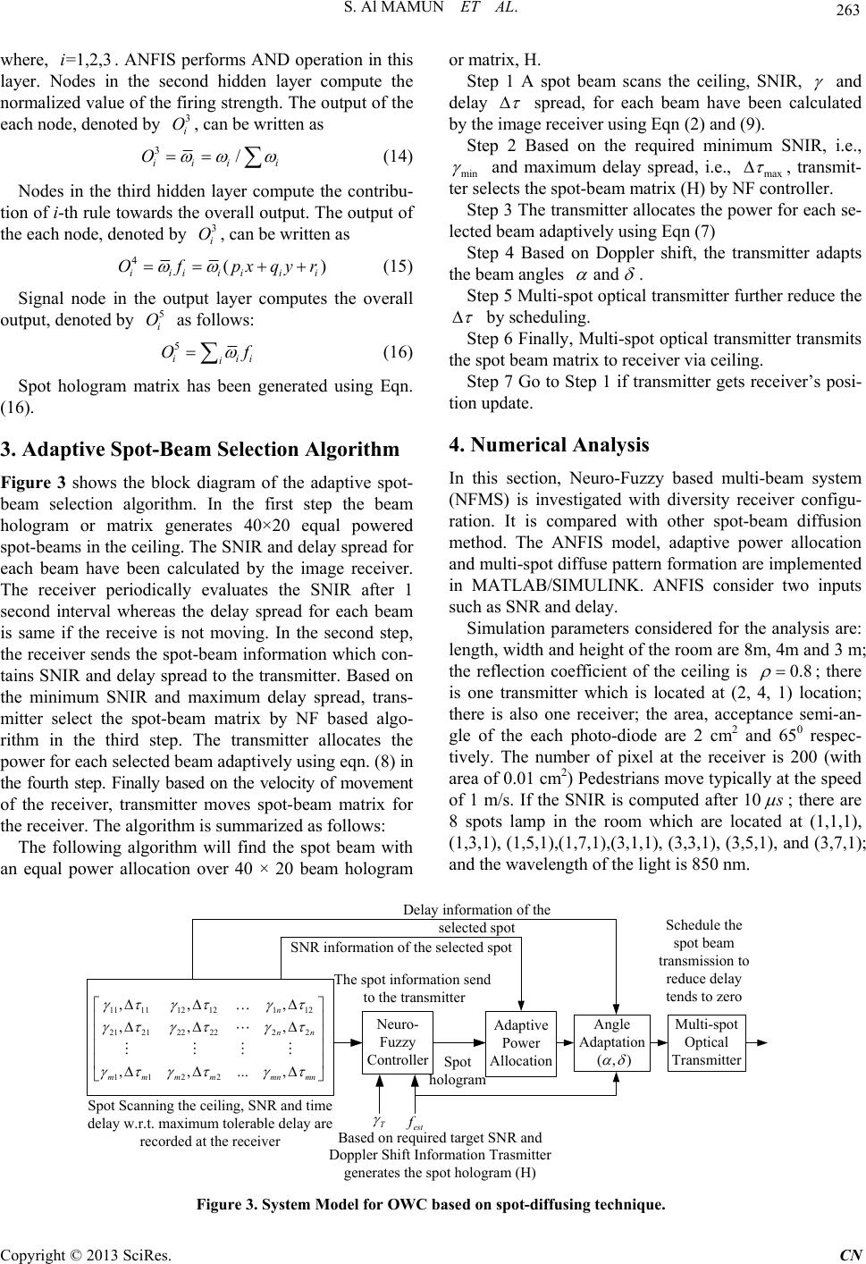 S. Al MAMUN ET AL. Copyright © 2013 SciRes. CN 263 where, . ANFIS performs AND operation in this layer. Nodes in the second hidden layer compute the normalized value of the firing strength. The output of the each node, denoted by , can be written as =1,2,3i 3 i O 3/ iii Oi (14) Nodes in the third hidden layer compute the contribu- tion of i-th rule towards the overall output. The output of the each node, denoted by , can be written as 3 i O 4( iiiiiii Of pxqy )r (15) Signal node in the output layer computes the overall output, denoted by as follows: 5 i O 5 i i O i i f (16) Spot hologram matrix has been generated using Eqn. (16). 3. Adaptive Spot-Beam Selection Algorithm Figure 3 shows the block diagram of the adaptive spot- beam selection algorithm. In the first step the beam hologram or matrix generates 40×20 equal powered spot-beams in the ceiling. The SNIR and delay spread for each beam have been calculated by the image receiver. The receiver periodically evaluates the SNIR after 1 second interval whereas the delay spread for each beam is same if the receive is not moving. In the second step, the receiver sends the spot-beam information which con- tains SNIR and delay spread to the transmitter. Based on the minimum SNIR and maximum delay spread, trans- mitter select the spot-beam matrix by NF based algo- rithm in the third step. The transmitter allocates the power for each selected beam adaptively using eqn. (8) in the fourth step. Finally based on the velocity of movement of the receiver, transmitter moves spot-beam matrix for the receiver. The algorithm is summarized as follows: The following algorithm will find the spot beam with an equal power allocation over 40 × 20 beam hologram or matrix, H. Step 1 A spot beam scans the ceiling, SNIR, and delay spread, for each beam have been calculated by the image receiver using Eqn (2) and (9). Step 2 Based on the required minimum SNIR, i.e., min and maximum delay spread, i.e., max , transmit- ter selects the spot-beam matrix (H) by NF controll er . Step 3 The transmitter allocates the power for each se- lected beam adaptively using Eqn (7) Step 4 Based on Doppler shift, the transmitter adapts the beam angles and . Step 5 Multi-spot optical transmitter further reduce the by scheduling. Step 6 Finally, Multi-spot optical transmitter transmits the spot beam matrix to receiver via ceiling. Step 7 Go to Step 1 if transmitter gets receiver’s posi- tion update. 4. Numerical Analysis In this section, Neuro-Fuzzy based multi-beam system (NFMS) is investigated with diversity receiver configu- ration. It is compared with other spot-beam diffusion method. The ANFIS model, adaptive power allocation and multi-spot diffuse pattern formation are implemented in MATLAB/SIMULINK. ANFIS consider two inputs such as SNR and delay. Simulation parameters considered for the analysis are: length, width and height of the room are 8m, 4m and 3 m; the reflection coefficient of the ceiling is 0.8 ; there is one transmitter which is located at (2, 4, 1) location; there is also one receiver; the area, acceptance semi-an- gle of the each photo-diode are 2 cm2 and 650 respec- tively. The number of pixel at the receiver is 200 (with area of 0.01 cm2) Pedestrians move typically at the speed of 1 m/s. If the SNIR is computed after 10 ; there are 8 spots lamp in the room which are located at (1,1,1), (1,3,1), (1,5,1),(1,7,1),(3,1,1), (3,3,1), (3,5,1), and (3,7,1); and the wavelength of the light is 850 nm. Neuro- Fuzzy Controller 11 1112 12112 21 21222222 112 2 ,, , ,, , ,,... , n nn mmm mmnmn T est Spot Scanning the ceiling, SNR and time delay w.r.t. maximum tolerable delay are recorded at the receiver The spot information send to the transmit te r Based on required target SNR and Doppler Shift Information Trasmitter generates t he spot hologra m (H) Adaptive Power Allocation Spot hologram Delay information of the selected spot Multi-spot Optical Transmitter Schedule the spot beam transmission to reduce del ay tends to zero SNR information of the selected spot Angle Adaptation (,) Figure 3. System Mo de l for OWC based on spot-diffusing technique. 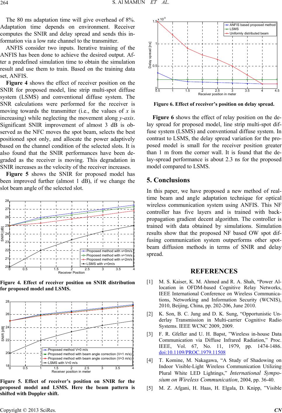 S. Al MAMUN ET AL. 264 The 80 ms adaptation time will give overhead of 8%. Adaptation time depends on environment. Receiver computes the SNIR and delay spread and sends this in- formation via a low rate channel to the transmitter. ANFIS consider two inputs. Iterative training of the ANFIS has been done to achieve the desired output. Af- ter a predefined simulation time to obtain the simulation result and use them to train. Based on the training data set, ANFIS. Figure 4 shows the effect of receiver position on the SNIR for proposed model, line strip multi-spot diffuse system (LSMS) and conventional diffuse system. The SNR calculations were performed for the receiver is moving towards the transmitter (i.e., the values of x is increasing) while neglecting the movement along y-axis. Significant SNIR improvement of almost 3 dB is ob- served as the NFC moves the spot beam, selects the best positioned spot only, and allocate the power adaptively based on the channel condition of the selected slots. It is also found that the SNIR performances have been de- graded as the receiver is moving. This degradation in SNIR increases as the velocity of the receiver increases. Figure 5 shows the SNIR for proposed model has been improved further (almost 1 dB), if we change the slot beam angle of the selected slot. 00.5 11.5 22.5 33.5 4 20 21 22 23 24 25 26 27 28 Receiver Position SNIR [dB] Proposed method with v=0m/s Proposed method with v=1m/s Proposed method with v=2m/s LSMS with v=0m/s Figure 4. Effect of receiver position on SNIR distribution for proposed model and LSMS. 00.5 11.5 22.5 33.5 4 18 20 22 24 26 28 Rec eiver posit ion in meter SNIR [dB] Proposed method V=0 m/s Proposed method with beam angle correction (V=1 m/s) Proposed method with beam angle correction (V=3 m/s) LSMS with V=0 m/s Figure 5. Effect of receiver’s position on SNIR for the proposed model and LSMS. Here the beam pattern is shifted with Doppler shift. 0.5 11.5 22.5 33.5 44.5 0 0.5 1 1.5x 10 -9 Receiver position in meter Delay spread [ns] ANFI S ba s ed p r oposed method LSMS Uniformly dis t rib ut ed be am Figure 6. Effect of receiver’s position on delay spread. Figure 6 shows the effect of relay position on the de- lay spread for proposed model, line strip multi-spot dif- fuse system (LSMS) and conventional diffuse system. In contrast to LSMS, the delay spread variation for the pro- posed model is small for the receiver position greater than 1 m from the corner wall. It is found that the de- lay-spread performance is about 2.3 ns for the proposed model compared to LSMS. 5. Conclusions In this paper, we have proposed a new method of real- time beam and angle adaptation technique for optical wireless communication system using ANFIS. This NF controller has five layers and is trained with back- propagation gradient decent algorithm. The controller is trained with data obtained by simulations. Simulation results show that the proposed NF based OW spot dif- fusing communication system outperforms other spot- beam diffusion methods in terms of SNIR and delay spread. REFERENCES [1] M. S. Kaiser, K. M. Ahmed and R. A. Shah, “Power Al- location in OFDM-based Cognitive Relay Networks, IEEE International Conference on Wireless Communica- tions, Networking and Information Security (WCNIS), 2010, Beijing, China, pp. 202-206, June 2010. [2] K. Son, B. C. Jung and D. K. Sung, “Opportunistic Un- derlay Transmission in Multi-carrier Cognitive Radio Systems. IEEE WCNC 2009, 2009. [3] F. R. Gfeller and U. H. Bapst, ”Wireless in-house Data Communication via Diffuse Infrared Radiation,” Proc. IEEE, Vol. 67, No. 11, 1979, pp. 1474-1486. doi:10.1109/PROC.1979.11508 [4] T. Komine, M. Nakagawa, “A Study of Shadowing on Indoor Visible-Light Wireless Communication Utilizing Plural White LED Lightings,” International Sympo- sium on Wireless Communication, 2004, pp. 36-40. [5] M. Z. Afgani, H. Haas, H. Elgala, D. Knipp, ”Visible Copyright © 2013 SciRes. CN  S. Al MAMUN ET AL. 265 light Communication Using OFDM,” Proc. IEEE Symp. on Wireless Pervasive Computing, TRIDENTCOM 2006. [6] T. Komine and M. Nakagawa, “Fundamental Analysis for Visible-Light Communication System Using LED Lights,” IEEE Transactions On Consumer Electron., Vol. 50, 2004, pp. 100-107. [7] M. Akbulut, C. Chen, M. Hargis, A. Weiner, M. Melloch, and J. Woodall, “Digital Communications Above 1 Gb/s Using 890-nm Surface-Emitting Light-Emitting Diodes,” IEEE Photonics Technology Letters, Vol. 13, No. 1, 2001, pp. 85-87. doi:10.1109/68.903229 [8] F. E. Alsaadi, M. Nikkar and Jaafar M. H. Elmirghani, “Adaptive Mobile Optical Wireless Systems Employing a Beam Clustering Method, Diversity Detection, and Relay Nodes,” IEEE Transactions on Communications, Vol. 58, 2010, No. 3. doi:10.1109/TCOMM.2010.03.080361 [9] M. T. Alresheedi and J. M. H. Elmirghani, “10 Gb/s In- door Optical Wireless Systems Employing Beam Delay, Power, and Angle Adaptation Methods with Imaging Dectection,” Journal of Lightwave Technology, Vol. 30, No. 12, 2012. [10] M. N. Esfahani and J. M. H. Elmirghani, “A Genetic Al- gorithm Method for Multi Spot Diffuse Infrared Wireless Communication,” London Communication Symposium, 2009. [11] Z. Ghassemlooy and S. Rajbhandari, “Performance of Diffused Indoor Optical Wireless Links Employing Neu- ral and Adaptive Linear Equalizers,” ICICS 2007. [12] D. K. Borah1, A. C. Boucouvalas, C. C. Davis, S. Hranilovic and K. Yiannopoulos, “A Review of Commu- nication-oriented Optical Wireless Systems,” EURASIP Journal on Wireless Communications and Networking, 2012 : 91. Copyright © 2013 SciRes. CN
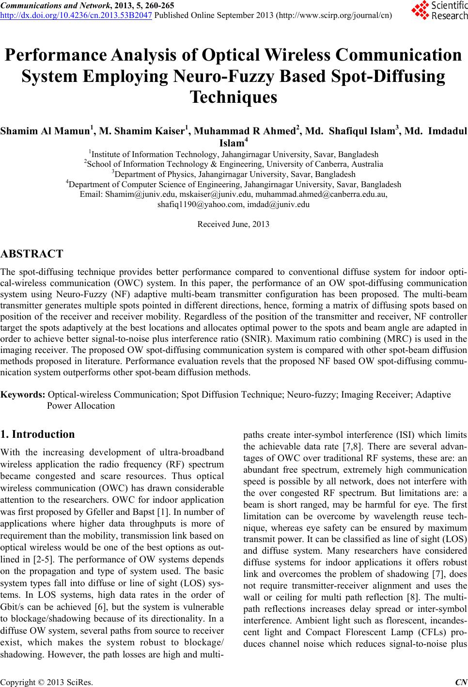
|