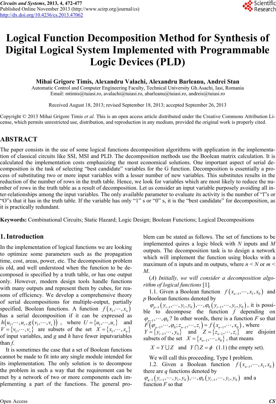
 Circuits and Systems, 2013, 4, 472-477 Published Online November 2013 (http://www.scirp.org/journal/cs) http://dx.doi.org/10.4236/cs.2013.47062 Open Access CS Logical Function Decomposition Method for Synthesis of Digital Logical System Implemented with Programmable Logic Devices (PLD) Mihai Grigore Timis, Alexandru Valachi, Alexandru Barleanu, Andrei Stan Automatic Control and Computer Engineering Faculty, Technical University Gh.Asachi, Iasi, Romania Email: mtimis@tuiasi.ro, avalachi@tuiasi.ro, abarleanu@tuiasi.ro, andreis@tuiasi.ro Received August 18, 2013; revised September 18, 2013; accepted September 26, 2013 Copyright © 2013 Mihai Grigore Timis et al. This is an open access article distributed under the Creative Commons Attribution Li- cense, which permits unrestricted use, distribution, and reproduction in any medium, provided the original work is properly cited. ABSTRACT The paper consists in the use of some logical functions decomposition algorithms with application in the implementa- tion of classical circuits like SSI, MSI and PLD. The decomposition methods use the Boolean matrix calculation. It is calculated the implementation costs emphasizing the most economical solutions. One important aspect of serial de- composition is the task of selecting “best candidate” variables for the G function. Decomposition is essentially a pro- cess of substituting two or more input variables with a lesser number of new variables. This substitutes results in the reduction of the number of rows in the truth table. Hence, we look for variables which are most likely to reduce the nu- mber of rows in the truth table as a result of decomposition. Let us consider an input variable purposely avoiding all in- ter-relationships among the input variables. The only available parameter to evaluate its activity is the number of “l”s or “O”s that it has in the truth table. If the variable has only “1” s or “0” s, it is the “best candidate” for decomposition, as it is practically redundant. Keywords: Combinational Circuits; Static Hazard; Logic Design; Boolean Functions; Logical Decompositions 1. Introduction In the implementation of logical functions we are looking to optimize some parameters such as the propagation time, cost, areas, power, etc. The decomposition problem is old, and well understood when the function to be de- composed is specified by a truth table, or has one output only. However, modern design tools handle functions with many outputs and represent them by cubes, for rea- sons of efficiency. We develop a comprehensive theory of serial decompositions for multiple-output, partially specified, Boolean functions. A function 1,, n xx 1,, r u has a serial decomposition if it can be expressed as s , where and 11 ,,,,, r huu gvv 1,, Uu Vv v are subsets of the set 1,, n xx of input variables, and g and h have fewer inputvariables than f. It is sometimes the case that a set of Boolean functions cannot be made to fit into any single module intended for its implementation. The only solution is to decompose the problem in such a way that the requirement can be met by a network of two or more components each im- plementing a part of the functions. The general pro- blem can be stated as follows. The set of functions to be implemented quires a logic block with N inputs and M outputs. The decomposition task is to design a network which will implement the function using blocks with a maximum of n inputs and m outputs, where n < N or m < M. (A) Initially, we will consider a decomposition algo- rithm of logical functions [1]. 1.1. Given a Boolean function 110 ,,, n xxx and p Boolean functions denoted by 1 1100110 ,,,,,,,, pi i yyy yy 10 ,, p , it is possi- ble to decompose the function f depending on ? In other words, there is a function F so that 101 10 ,,; ,,,, pnin zzfxx , where 10 ,, i Yy y 1,, ni and zz are disjoint subsets of the set 10 ,, n xx , that means YZ and YZ (1.1) (the empty set). We will call this proceeding, Type I problem. 1.2. Given a Boolean function 110 ,,, n xxx there are q functions denoted by 0 , 1 110qi 0 11 ,,,,,,, i yyy y y and a function F so that 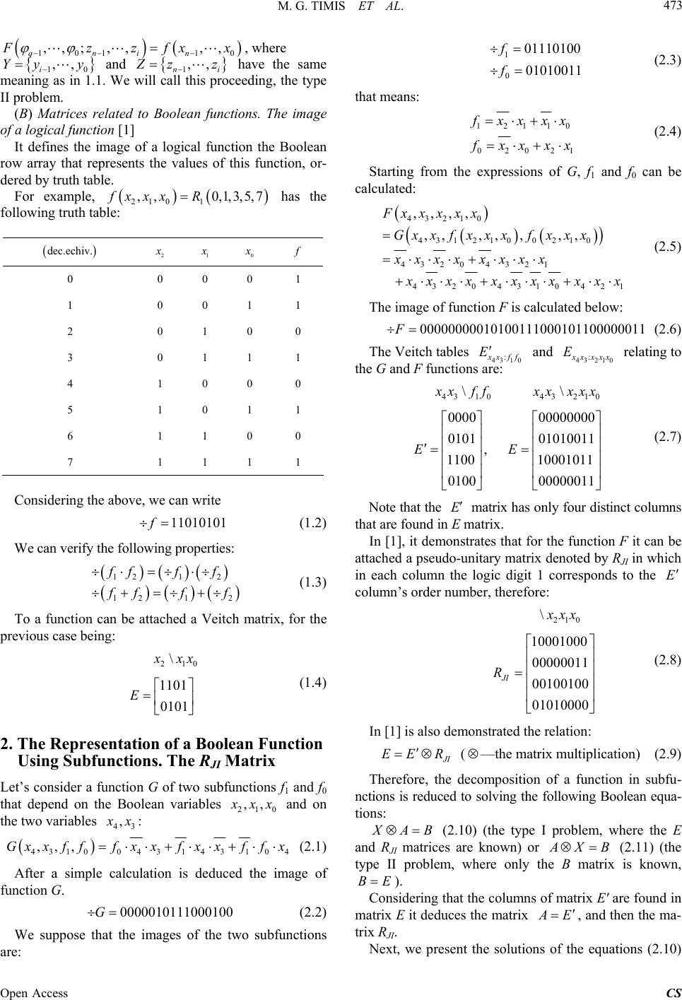 M. G. TIMIS ET AL. 473 101 10 ,,; ,,,, qnin zzfxx 10 ,, i Yy y 1,, ni , where and zz 210 1 ,, 0,1,3,fxxx R dec.echiv. 2 have the same meaning as in 1.1. We will call this proceeding, the type II problem. (B) Matrices related to Boolean functions. The image of a logical function [1] It defines the image of a logical function the Boolean row array that represents the values of this function, or- dered by truth table. For example, has the following truth table: 5,7 1 0 0 0 0 0 1 1 0 0 1 1 2 0 1 0 0 3 0 1 1 1 4 1 0 0 0 5 1 0 1 1 6 1 1 0 0 7 1 1 1 1 Considering the above, we can write 11010101f (1.2) We can verify the following properties: 121 2 1212 fff f ff f (1.3) To a function can be attached a Veitch matrix, for the previous case being: 210 \ 1101 0101 xx E (1.4) 2. The Representation of a Boolean Function Using Subfunctions. The RJI Matrix Let’s consider a function G of two subfunctions f1 and f0 that depend on the Boolean variables 210 ,, xx and on the two variables 43 , x: 43100 4 314 310 4 ,,,Gxxfff x xfx xffx (2.1) After a simple calculation is deduced the image of function G. 00000101110001 00G (2.2) We suppose that the images of the two subfunctions are: 1 0 01110100 01010011 f f (2.3) that means: 12110 02021 xx xx xx xx (2.4) Starting from the expressions of G, f1 and f0 can be calculated: 43210 431 2100210 4320 4321 4320431042 ,,,, ,,,, ,,, Fx xx xx Gxxfxxxf xxx xxxx xxxx 1 xxx xxxxxxx (2.5) The image of function F is calculated below: 00000000010100 111000101 100000011F (2.6) The Veitch tables 43 10 : xff E and 43 210 : xxxx E relating to the G and F functions are: 43 1043210 \\ 0000 00000000 0101 01010011 , 1100 10001011 0100 00000011 xffxxxxx EE (2.7) Note that the E matrix has only four distinct columns that are found in E matrix. In [1], it demonstrates that for the function F it can be attached a pseudo-unitary matrix denoted by RJI in which in each column the logic digit 1 corresponds to the E column’s order number, therefore: 210 \ 10001000 00000011 00100100 01010000 JI xx R (2.8) In [1] is also demonstrated the relation: I EE R ( —the matrix multiplication) (2.9) Therefore, the decomposition of a function in subfu- nctions is reduced to solving the following Boolean equa- tions: AB (2.10) (the type I problem, where the E and RJI matrices are known) or XB (2.11) (the type II problem, where only the B matrix is known, BE ). Considering that the columns of matrix E' are found in matrix E it deduces the matrix E , and then the ma- trix RJI. Next, we present the solutions of the equations (2.10) Open Access CS  M. G. TIMIS ET AL. 474 and (2.11), demonstrated in [1]. A. The solution of the equation XB [1] a) Let’s consider X a some matrix. It is valid the relation (2.12), [1]. A tB (tA-the transpose of the matrix A) (2.12) b) Let’s consider X a pseudo-unitary matrix. It is valid the relation (2.13) [1]. AA tBtB (2.13) B. The solution of the equation AB [1] a) Let’s consider A a some matrix. It is assumed [1]: A Bt (2.14) b) Let’s consider A a pseudo-unitary matrix. It is denoted by cA Bt and aA Bt. The suffi- cient condition of existence of the solution [1] is: and cAaAc a BtXBtXXX (2.15) If ca X or ca X, there is no solution for the matrix X. In this case it is trying to solve the following equations: 40 14310 1 43210 ,, ,,, ,,,, Fx x Gxxff xxxxx (2.16) (the previous solution) or 40 24310 2 43210 ,, ,,, ,,,, Fx x Gxxff xxxxx (2.17) (the consequence solution). We will return to these prob- lems in a future paper. 3. Examples (A) Let’s consider the function defined by 43210 1 ,,,, 0,3,5,6,9,10,12,14,15,16,17,18,19,21, 22,30 Fx xx xx R(3.1) Applying the Veitch-Karnaugh method [2], a minimal form is given by the expression: 4321043 210 3210 32104310 43204321 432 210 3210 ,,,,Fxxxxxxxxxx xxx xxxx xxxx xxxxxxxx xxx xxx xxxx (3.2) We define the cost of implementation as the number of the inputs in the basic circuits, components [3]. In the previous case, by implementing with AND-OR circuits, results: 1564239 44CF . (It is consi- dering that the input variables are provided inverted and non-inverted, i.e. , ii x.) Let’s consider the following possible decomposition: 4310 43210 ,,, ,,,,Gxxff Fxxxxx where 11210 ,, fxxx, 00210 ,, fxxx. For the function F corresponds the following Veitch matrix, denoted by E: 10010110 01101011 11110110 00000010 E (3.3) Matrix E having four distinct columns, a solution for E is: 43 10 \ 1001 0111 1101 0001 xff E (3.4) Therefore, the matrix RJI, solution of the equation JI ER E , is: 10010100 01100000 00001001 00000010 JI EE Rt Et E (3.5) From where we obtain: 1 0 00001011 01100010 f f (3.6) or after an elementary calculation: 1210 01021 fxxx 0 xx xxx (3.7) Using E' matrix we obtain: 103 10430 430 143 Gffxffxxf xxf fxx (3.8) with a possible implementation as in Figure 1. So, we will have: 10 7CfCf 8 (3.9) 43 2519CG , so that 34CF . Open Access CS  M. G. TIMIS ET AL. 475 Figure 1. The implementation of the function F, using sub- functions. (B) Implementation using programmable logic devices (PLD) We will consider a circuit PAL10L8 [4], which has 10 inputs, 8 outputs and having an AND-OR configuration, each NOR having 2 inputs, with the structure illustrated in Figure 2. Let’s consider the previous function: 8 0i i m , where 0 43210 13210 23210 33210 44310 5 4320 6 4321 7432 8210 mxxxxx mxxxx mxxxx mxxxx mxxxx mxxxx mxxxx mxxx mxxx (3.10) Figure 2. The circuit PAL10L8. We will use the following algorithm: 001 102 768 Qmm QQm QQmF (3.11) Therefore, 1ii i QQ m 1 with , 10 Qm 07i . Will be needed: 9—product terms , 08 mm 7— i Q terms 06i , so it will be used 16 product terms from maximum 20. But the number of inputs is insufficient (see Figure 3). Classic, we should also use two circuits (PAL10L8), or a single circuit with greater capacity. Let go back to the same function that uses the subfunctions f1, f0, which have the expressions: 12120 01021 fxxxx 0 xx xxx and 43210 4310 103 10 130 430 143 ,,,, ,,, Fx xxxx Gx xff fxff xxf xxf fxx (3.12) Therefore, after a preliminary evaluation we have: 4 product terms 10 , f and 5 product terms for function G. Let’s consider 0123 4 Gaaaaa , where ai are the terms of the decomposed function. A PAL im- plementation is like in Figures 3 and 4. Open Access CS 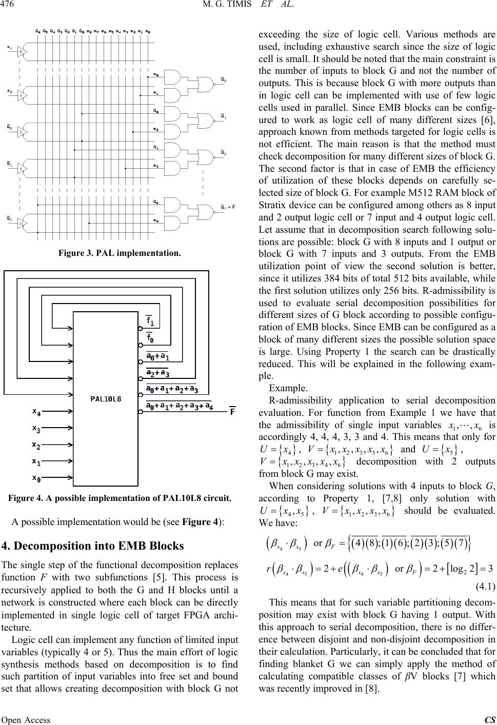 M. G. TIMIS ET AL. 476 Figure 3. PAL implementation. Figure 4. A possible implementation of PAL10L8 circuit. A possible implementation would be (see Figure 4): 4. Decomposition into EMB Blocks The single step of the functional decomposition replaces function F with two subfunctions [5]. This process is recursively applied to both the G and H blocks until a network is constructed where each block can be directly implemented in single logic cell of target FPGA archi- tecture. Logic cell can implement any function of limited input variables (typically 4 or 5). Thus the main effort of logic synthesis methods based on decomposition is to find such partition of input variables into free set and bound set that allows creating decomposition with block G not exceeding the size of logic cell. Various methods are used, including exhaustive search since the size of logic cell is small. It should be noted that the main constraint is the number of inputs to block G and not the number of outputs. This is because block G with more outputs than in logic cell can be implemented with use of few logic cells used in parallel. Since EMB blocks can be config- ured to work as logic cell of many different sizes [6], approach known from methods targeted for logic cells is not efficient. The main reason is that the method must check decomposition for many different sizes of block G. The second factor is that in case of EMB the efficiency of utilization of these blocks depends on carefully se- lected size of block G. For example M512 RAM block of Stratix device can be configured among others as 8 input and 2 output logic cell or 7 input and 4 output logic cell. Let assume that in decomposition search following solu- tions are possible: block G with 8 inputs and 1 output or block G with 7 inputs and 3 outputs. From the EMB utilization point of view the second solution is better, since it utilizes 384 bits of total 512 bits available, while the first solution utilizes only 256 bits. R-admissibility is used to evaluate serial decomposition possibilities for different sizes of G block according to possible configu- ration of EMB blocks. Since EMB can be configured as a block of many different sizes the possible solution space is large. Using Property 1 the search can be drastically reduced. This will be explained in the following exam- ple. Example. R-admissibility application to serial decomposition evaluation. For function from Example 1 we have that the admissibility of single input variables 16 ,, x is accordingly 4, 4, 4, 3, 3 and 4. This means that only for 4 Ux, 12 356 ,,,,Vxxxxx and U, 5 x ,,xxxx 12346 decomposition with 2 outputs from block G may exist. ,,V x When considering solutions with 4 inputs to block G, according to Property 1, [7,8] only solution with 45 ,Uxx, 12 3 6 ,,,Vxxxx should be evaluated. We have: 45 45 452 or 48;16;23;57 2 or 2log23 xx F xxxx F re (4.1) This means that for such variable partitioning decom- position may exist with block G having 1 output. With this approach to serial decomposition, there is no differ- ence between disjoint and non-disjoint decomposition in their calculation. Particularly, it can be concluded that for finding blanket G we can simply apply the method of calculating compatible classes of βV blocks [7] which was recently improved in [8]. Open Access CS 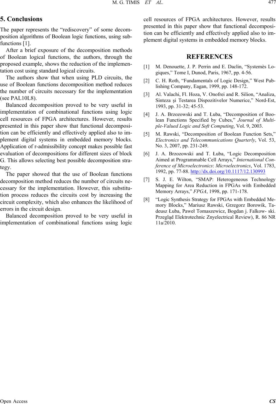 M. G. TIMIS ET AL. Open Access CS 477 5. Conclusions The paper represents the “rediscovery” of some decom- position algorithms of Boolean logic functions, using sub- functions [1]. After a brief exposure of the decomposition methods of Boolean logical functions, the authors, through the proposed example, shows the reduction of the implemen- tation cost using standard logical circuits. The authors show that when using PLD circuits, the use of Boolean functions decomposition method reduces the number of circuits necessary for the implementation (see PAL10L8). Balanced decomposition proved to be very useful in implementation of combinational functions using logic cell resources of FPGA architectures. However, results presented in this paper show that functional decomposi- tion can be efficiently and effectively applied also to im- plement digital systems in embedded memory blocks. Application of r-admissibility concept makes possible fast evaluation of decompositions for different sizes of block G. This allows selecting best possible decomposition stra- tegy. The paper showed that the use of Boolean functions decomposition method reduces the number of circuits ne- cessary for the implementation. However, this substitu- tion process reduces the circuits cost by increasing the circuit complexity, which also enhances the likelihood of errors in the circuit design. Balanced decomposition proved to be very useful in implementation of combinational functions using logic cell resources of FPGA architectures. However, results presented in this paper show that functional decomposi- tion can be efficiently and effectively applied also to im- plement digital systems in embedded memory blocks. REFERENCES [1] M. Denouette, J. P. Perrin and E. Daclin, “Systemès Lo- giques,” Tome I, Dunod, Paris, 1967, pp. 4-56. [2] C. H. Roth, “Fundamentals of Logic Design,” West Pub- lishing Company, Eagan, 1999, pp. 148-172. [3] Al. Valachi, Fl. Hoza, V. Onofrei and R. Silion, “Analiza, Sinteza şi Testarea Dispozitivelor Numerice,” Nord-Est, 1993, pp. 31-32; 45-53. [4] J. A. Brzozowski and T. Łuba, “Decomposition of Boo- lean Functions Specified by Cubes,” Journal of Multi- ple-Valued Logic and Soft Computing, Vol. 9, 2003. [5] M. Rawski, “Decomposition of Boolean Function Sets,” Electronics and Telecommunications Quarterly, Vol. 53, No. 3, 2007, pp. 231-249. [6] J. A. Brzozowski and T. Łuba, “Logic Decomposition Aimed at Programmable Cell Arrays,” International Con- ference of Microelectronics: Microelectronics, Vol. 1783, 1992, pp. 77-88. http://dx.doi.org/10.1117/12.130993 [7] S. J. E. Wilton, “SMAP: Heterogeneous Technology Mapping for Area Reduction in FPGAs with Embedded Memory Arrays,” FPGA, 1998, pp. 171-178. [8] “Logic Synthesis Strategy for FPGAs with Embedded Me- mory Blocks,” Mariusz Rawski, Grzegorz Borowik, Ta- deusz Łuba, Paweł Tomaszewicz, Bogdan j. Falkow- ski. Przegląd Elektrotechnic Znyelectrical Review), R. 86 NR 11a/2010.
|