 Communications and Network, 2013, 5, 57-64 http://dx.doi.org/10.4236/cn.2013.53B2012 Published Online September 2013 (http://www.scirp.org/journal/cn) Modulation for Digital Radio Broadcasting Using Amplitude Autocorrelation of Pseudo Random Noise Codes to Carry Information Fabrício de Araújo Carvalho, Fernando Walter Departamento de Telecomunicações, Instituto Tecnológico de Aeronáutica, São José dos Campos, Brazil Email: eng.fabricio.carvalho@gmail.com, fabricio@ita.br, fw2@ita.br Received June, 2013 ABSTRACT The frequency bands used in mobile communications are allocated according to the type of application. With the need for more channels, the frequency spectrum has become a scarce natural resource. This study shows the results of a pro- posed modulation using a variation of the autocorrelation of pseudo-random codes to carry information. The work also presents the generation of multiple orthogonal axes to increase the bit rate thus improving the channel efficiency. Keywords: Digital Radio Broadcasting; Spectral Efficiency; Pseudo Random Codes; CDMA; SDR 1. Introduction The perception of the environment that surrounds us and information generated from this perception are rational- ized to form our knowledge. This knowledge is vital to the survival of the individuals and the society in which they live. This knowledge is the result of lived and ra- tionalized experiences, but the ability to communicate allows its transfer among members of different groups, so that this knowledge is incorporated into the experi- ences of others. The transfer of knowledge ensures its elaboration, its improvement, as well as its maintenance over the years. No person aware of a common problem fails to share it with a neighbor or warn him/her of a danger. The diffi- culties and the existing obstacles in our way of living sharpen our thinking and responses to problems to be communicated to the others. The knowledge spreads through verbal and visual communication, and perpetuates in books, drawings and paintings, as well as in the memory of individuals. It is therefore a cumulative process, the result of the senses, reasoning and communication. Over the centuries, technological advances have al- lowed the expansion of the media. In the media today, the information is propagated mainly by electromagnetic waves and digital files. Today, the state of the art elec- tronic systems also allow the machines to communicate among themselves. Relatively traditional systems, such as phone systems, cell phones, computer networks, vi- deogames, PDAs (Personal Digital Assistants), TVs (to- day, smart TVs) go through a period of convergence and interactivity forming a large communication network. In this context, the frequency spectrum used by all these agents of communication has become a scarce nat- ural resource. The communication frequencies are allocated accord- ing to the type of application and transmission medium. We particularly observed a useful spectrum for AM and FM radio transmission (Figure 1), where we note scar- city of ranges in relation to the demand for new services. Figure 1. Allocation of Frequencies: 54.0 - 117.975 MHz (Source: National Telecommunications and Information Admini- stration, http://www.ntia.doc.gov/osmhome/allochrt.html). C opyright © 2013 SciRes. CN  F. de A. CARVALHO, F. WALTER 58 This demand requires a continuous search for new technologies. Since 2005, the Brazilian government has opened a public call for submission of new proposals and assessments of the existing digital radio. Meanwhile, some universities and federal institutes are developing studies with the same purpose. 2. Digital Radio Having the goal of developing a communication system capable of operating with existing systems and with a power close to the thermal noise, we adopted, as a start- ing point, the CDMA DS technique, widely used in mo- bile communication systems. In the CDMA technique pseudo-random codes are used (Pseudo Random Noise - PRN) allowing access several channels to the environ- ment using the same carrier frequency. With the development of the first prototype of broad- cast radio (transmitter and receiver) using only the BPSK modulation, we found a low bit rate for audio/video ap- plications. Because of this, the work has been directed to increase the number of bits per symbol, thus resulting in the proposed modulation for better transmission of the audio signal. The proposed modulation shows a method of adding more information per code period by exploring the am- plitude of autocorrelation of the PRN code. The signals are generated and processed using baseband processing techniques with digital signals. 2.1. PRN Codes The used PRN codes are called Gold codes. They are almost orthogonal to each other. They are formed by a binary sequence of “0`s” and “1`s”. In the pseudo- ran- dom sequences, the bits are called “chips”. The term chip is used to distinguish the bit of a code from a bit of the information. In Equation 1, we can see the representation of the PRN code ci (t) of the i-th transmitter. 1 0 ,0 Nchip iil il lchip tlT ctcc ou T 1 (1) where () represents a rectangular pulse of Tchip; cil duration corresponding to the value of the chip (“0” and “1”) for a given l; l being a counter from 0 to N-1; N is the number of chips of the code. The sequence ci(t) is periodic (Equation 2), period TC (N x Tchip). 1 00 Nchip C iil kl chip tlT kT ct cT (2) The sequence can be converted to Ci(t) of “1`s” and “-1`s” if the multiply operation is used to modulate the signal (Equation 3): cos . ii Ct ct (3) The used sequence is generated from two registers of maximum length, denominated as G1 and G2 Figure 2, for sequence with length of 511 (29 - 1) registration chips are used with 9 cells or elements. Both records are ini- tialized with 1`s to operate with module 2 ( ). Each record has its values shifted according to a time reference, which determines the rate of the chip and hence the code period. Table 1 presents the G1(t) and G2(t) polynomials used to match the value in each element of G1 and G2 registers. Figure 3 shows the sequence of chips provided by PRN code generator (Figure 2). Figure 2. Generator of gold codes. Table 1. PRN code generator polynomials. Reg. Polynomial Initialization G1(t) 94 1xx 111111111 G2(t) 9 1xxxx 643 111111111 Figure 3. PRN sequence of 511 chips of Gold code genera- tor. Copyright © 2013 SciRes. CN  F. de A. CARVALHO, F. WALTER 59 The PRN sequence identifies what the tuned radio sta- tion is. The distinction by the receiver between the transmitters is made through a correlation process. The correlation occurs between the code contained in the re- ceived signal and its replica generated in the receiver and measurement of the degree of similarity between these signals by amplitude of correlation. The amplitude of correlation between distinct PRN`s and orthogonals is approximately equal to zero, Rij (τ) (cross-correlation) for a delay τ (Equation 4). 0 10; / chip NT iji j RCt Ctdtpqualquer NT (4) In this equation, Ci(t) and Cj(t) are the PRN codes for the i-th and j-th transmitter, respectively. For the autocorrelation, Rii (τ), the amplitude is non- zero for delays τ less than a chip; 0 ≤ |τ| ≤ T chip, and are approximately zero for delays, τ, larger than the chip (Equation 5). 2 0 1; 1 0; chip NT chip c iii i chip chip Apara T T RCtCtdt NT para T (5) As noted, the autocorrelation peak has the width of two chips and repeats every period (N x Tchip) of the code. The amplitude increases linearly from a prior chip to maximum alignment and drops to approximately zero one chip after the maximum (Figure 4). A2 chip TN )1( chip TN )1( chip TN )1( chip TN )1( 2 A )( R chip NT chip T chip T chip NT chip T Figure 4. Process of autocorrelation of a PRN sequence. The autocorrelation for this code is shown in Figure 5. In it the maximum values of non standard amplitudes can be observed [511, 31, -1, -33]. The sequence was delayed 250 chips to center the maximum amplitude. 2.2. PWM In the existing modulations, three parameters of the car- rier are modified to transmit information: the phase, the frequency and its amplitude. In this proposal, in order to increase the number of bits per symbol by exploring the dynamic range of the auto- correlation amplitude of a given PRN sequence, we varied the width of the chip via a modified PWM called CWM, where the letter C represents the initial chip (with ampli- tude values +1 and -1), Figure 6. In this example, with four bits we can obtain 16 levels of the cyclic variation of the CWM, which is equivalent to dividing the maximum amplitude of autocorrelation into 16 levels. Therefore, the transport of the information on the correlation amplitude can transmit more than one bit per code; in this case four bits. To further increase the bit rate, new orthogonal axes were created. 2.3. Dimensional Generator The different PRN codes can be viewed as orthogonal or approximately orthogonal subcarriers (as in OFDM modulation). The number of distinct codes of the same length is, however, limited. The ideal for the initial design of the system is that each station is characterized by only one PRN code. A good solution found and used so far, is working with the same code for all axes, but with fixed displacement of n chips between them. This solution intends to save the number of PRN codes for a given geographic area and 50 100 150 200250 300350 400450 500 0 50 100 150 200 250 300 350 400 450 500 X: 148 Y: 31 Correla ção Am plitude Chi p s X: 251 Y: 511 Figure 5. Autocorrelation of pseudo-random codes. Chip period (Tc) 0000 0001 0010 0011 0100 Word: 4 bits PWM 1 -1 1 -1 1 -1 1 -1 1 -1 Figure 6. Control of the width of the chip. The width is a function of the binary word from the A/D converter of au- dio. thus enables more channels to be used, therefore, more Copyright © 2013 SciRes. CN  F. de A. CARVALHO, F. WALTER 60 stations, and more community radios. Figure 7 shows 3 axes with maximum amplitude. It means in this case that all three axes called X, Y and Z, are transmitting the same sequence of bits. In this case: X= 0000; Y= 0000; Z= 0000. From the point of view of the receiver, this solution is desirable because it facilitates the generation of internal signals by using only a code generator for tracking and demodulation. Another feature which will be seen later on is the iden- tification of the axes. The identification of only two axes is enough to locate the others. We need to remember that the relative displacement between the codes (axes) is fixed. We observed that all three axes are at the same value of maximum amplitude. But it is important to say that the value of maximum amplitude is not obtained for any rel- ative displacement between the axes. There are only a few points where we can achieve this balance. The iden- tification of these points and location of new axes com- poses this study. The modulation of chip width of direct sequences (DSCWM) resulted in the development of transmitter and its dual receiver. 3. DSCWM Transmitter The binary information coming from the A/D audio con- verter operates on the CWM (PWM chip), which deter- mines the width of the chip, and consequently the value of amplitude of autocorrelation obtained by the receiver during the correlation process between the signals. The CWM exists only in the transmitter. The signal generated internally by the receiver does not change the width of the chip, this way the amplitude obtained in the correla- tion is only a function of the transmitted information. A pilot channel containing the same code is needed to correctly decode the amplitude. It serves as a reference for the received power, in addition to synchronization and correction of Doppler shift on the carrier and the code. The block diagram, Figure 8, presents an overview for the DSCWM transmitter encoded on a digital baseband and digital intermediate frequency (IF). In this diagram, the voice signal is digitized by an A/D converter. The binary sequence provided by the converter controls the width of the code chip that carries the information. This signal is subsequently multiplied by the digital carrier and elevated to an intermediate frequency. The transmis- sion rate can increase with the addition of new orthogo- nal axes, with the component carrier in the quadrature. The oscillator serves as a time reference for the A/D converter and the frequency synthesizer, which is re- sponsible for determining the frequency for the other transmitter circuits: DSCWM modulator, PRN code gen- erator and CWM. The PRNs code generator provides pseudo-random sequence for the dimensional generator (code shifter) and the DSCWM modulator. The orthogonal axes generated by the dimensional generator, are modulated by CWM. Figure 9 shows the result of the digitalization of axis and the application of the duty cycle on each of them. Figure 7. The same pseudo-random code for the new axes is used. Frequency synthesi zer DSCWM modulator PRN code generator Compression of the data /N1 /N2 f0 = 10 MHz Broadcast signal Information Data Mapper A/D converter Local oscillator CWM1 CWM2 CWM3 CWM4 PRN Code Shifter CX CY CZ CW mixer Figure 8. Block diagram of the DSCWM transmitter in the baseband and digital IF. 1000 2000 3000 4000 5000 6000 7000 8000 0 1000 2000 3000 4000 5000 6000 7000 8000 X: 4320 Y: 7678 Correlação em X,Y,Z A mpli t ude Chips X: 5768 Y: 4866 X: 2408 Y: 5314 X: 189 Y: 6494 Figure 9. The same pseudo-random code is used for the new axes. Copyright © 2013 SciRes. CN 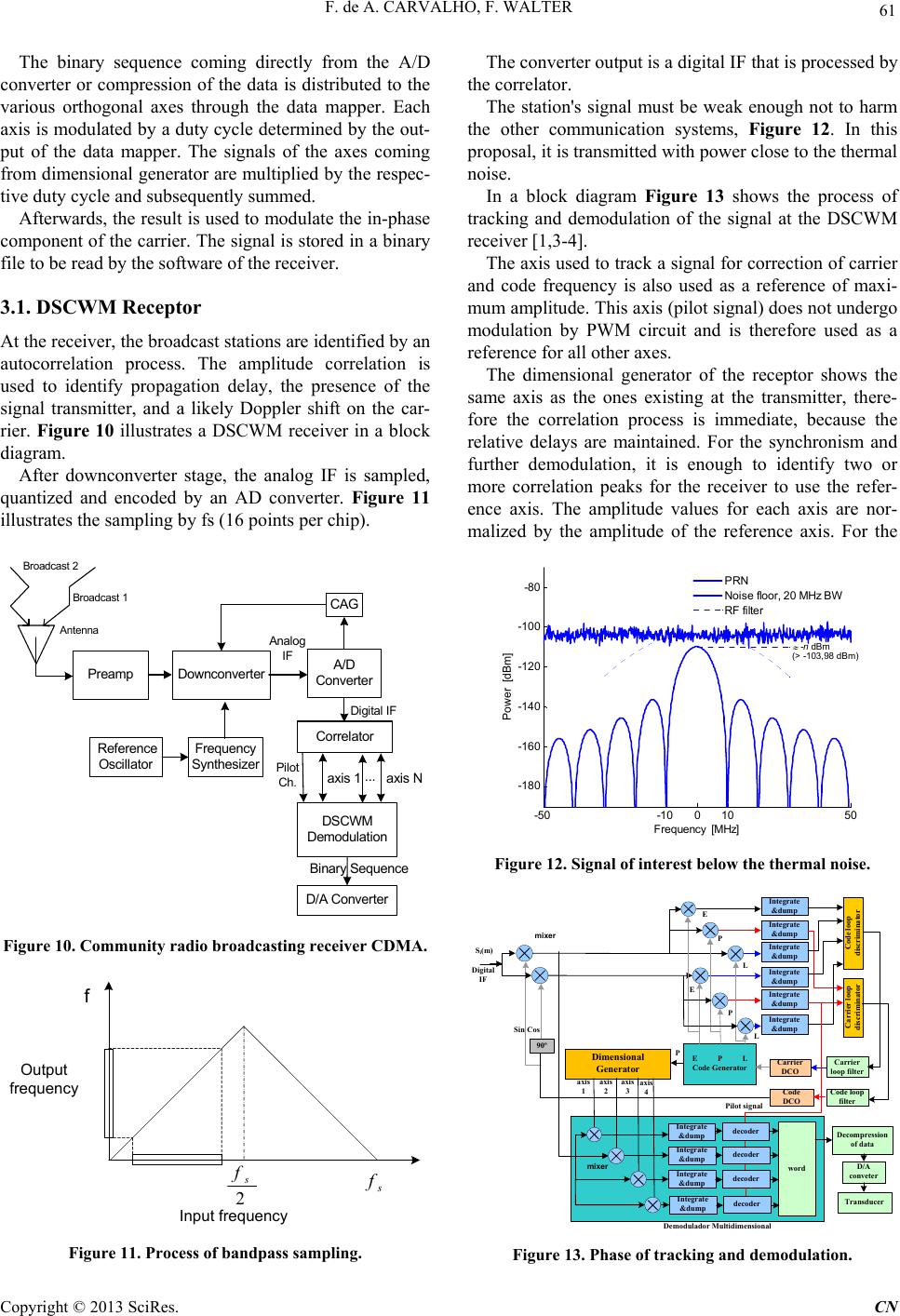 F. de A. CARVALHO, F. WALTER 61 The binary sequence coming directly from the A/D converter or compression of the data is distributed to the various orthogonal axes through the data mapper. Each axis is modulated by a duty cycle determined by the out- put of the data mapper. The signals of the axes coming from dimensional generator are multiplied by the respec- tive duty cycle and subsequently summed. Afterwards, the result is used to modulate the in-phase component of the carrier. The signal is stored in a binary file to be read by the software of the receiver. 3.1. DSCWM Receptor At the receiver, the broadcast stations are identified by an autocorrelation process. The amplitude correlation is used to identify propagation delay, the presence of the signal transmitter, and a likely Doppler shift on the car- rier. Figure 10 illustrates a DSCWM receiver in a block diagram. After downconverter stage, the analog IF is sampled, quantized and encoded by an AD converter. Figure 11 illustrates the sampling by fs (16 points per chip). Preamp Downconverter A/D Converter CAG Refe re n ce Oscillator DSCWM Demodulation D/A Converter Frequency Synthesizer Analog IF Digital IF Antenna Broadcast 1 Broadcast 2 Correlator Binary Sequence axis N axis 1... Pilot Ch. Figure 10. Community radio broadcasting receiver CDMA. 2 s fs f f Output frequency Input frequency Figure 11. Process of bandpas s sampling. The converter output is a digital IF that is processed by the correlator. The station's signal must be weak enough not to harm the other communication systems, Figure 12. In this proposal, it is transmitted with power close to the thermal noise. In a block diagram Figure 13 shows the process of tracking and demodulation of the signal at the DSCWM receiver [1,3-4]. The axis used to track a signal for correction of carrier and code frequency is also used as a reference of maxi- mum amplitude. This axis (pilot signal) does not undergo modulation by PWM circuit and is therefore used as a reference for all other axes. The dimensional generator of the receptor shows the same axis as the ones existing at the transmitter, there- fore the correlation process is immediate, because the relative delays are maintained. For the synchronism and further demodulation, it is enough to identify two or more correlation peaks for the receiver to use the refer- ence axis. The amplitude values for each axis are nor- malized by the amplitude of the reference axis. For the -50 -10 010 50 -180 -160 -140 -120 -100 -80 Frequency [ M H z] Power [dBm] -n dB m (> -1 03 ,98 d Bm ) PRN Noise f loor , 20 M Hz BW RF filter Figure 12. Signal of interest below the thermal noise. Integrate &dump Code loop discriminator Integrate &dump Integrate &dump Integrate &dump Integrate &dump Integrate &dump E P L Code Generator Carrier loop discriminator Code loop filter Code DCO 90º E E P P L L Carrier DCO Carrier loop filter Digital IF Si(m) Dimensional Generator word Pilot signal Decompression of data D/A conveter CosSin Transducer Demodulador Multidimensional Integrate &dump Integrate &dump Integrate &dump axis 1axis 2axis 3 P decoder decoder decoder Integrate &dump decoder axis 4 mixer mixer Figure 13. Phase of tracking and demodulation. Copyright © 2013 SciRes. CN 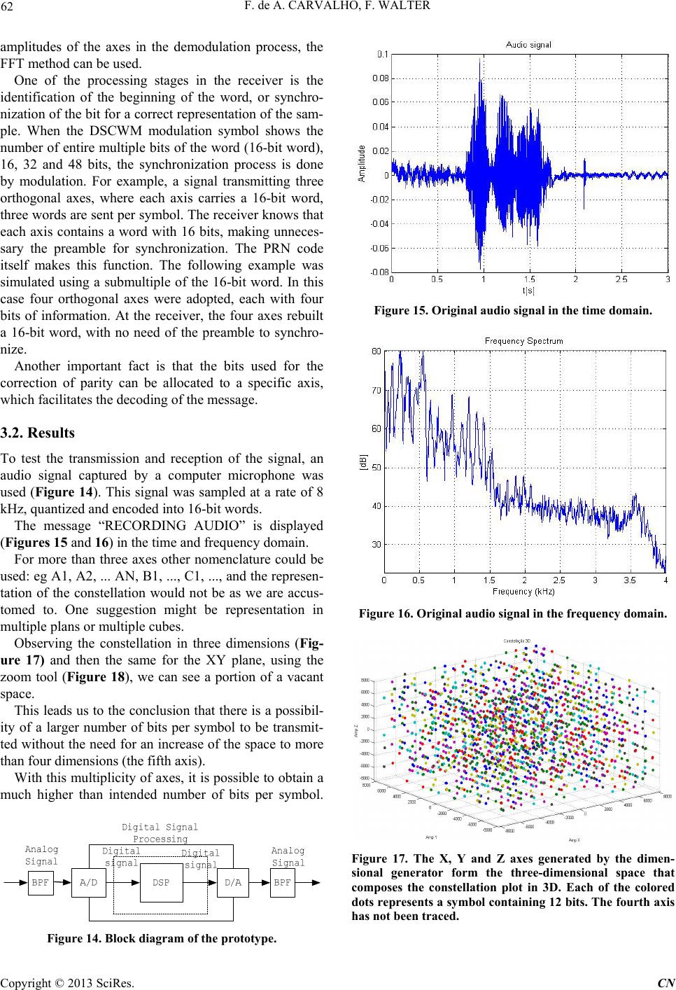 F. de A. CARVALHO, F. WALTER 62 amplitudes of the axes in the demodulation process, the FFT method can be used. One of the processing stages in the receiver is the identification of the beginning of the word, or synchro- nization of the bit for a correct representation of the sam- ple. When the DSCWM modulation symbol shows the number of entire multiple bits of the word (16-bit word), 16, 32 and 48 bits, the synchronization process is done by modulation. For example, a signal transmitting three orthogonal axes, where each axis carries a 16-bit word, three words are sent per symbol. The receiver knows that each axis contains a word with 16 bits, making unneces- sary the preamble for synchronization. The PRN code itself makes this function. The following example was simulated using a submultiple of the 16-bit word. In this case four orthogonal axes were adopted, each with four bits of information. At the receiver, the four axes rebuilt a 16-bit word, with no need of the preamble to synchro- nize. Another important fact is that the bits used for the correction of parity can be allocated to a specific axis, which facilitates the decoding of the message. 3.2. Results To test the transmission and reception of the signal, an audio signal captured by a computer microphone was used (Figure 14). This signal was sampled at a rate of 8 kHz, quantized and encoded into 16-bit words. The message “RECORDING AUDIO” is displayed (Figures 1 5 and 16) in the time and frequency domain. For more than three axes other nomenclature could be used: eg A1, A2, ... AN, B1, ..., C1, ..., and the represen- tation of the constellation would not be as we are accus- tomed to. One suggestion might be representation in multiple plans or multiple cubes. Observing the constellation in three dimensions (Fig- ure 17) and then the same for the XY plane, using the zoom tool (Figure 18), we can see a portion of a vacant space. This leads us to the conclusion that there is a possibil- ity of a larger number of bits per symbol to be transmit- ted without the need for an increase of the space to more than four dimensions (the fifth axis). With this multiplicity of axes, it is possible to obtain a much higher than intended number of bits per symbol. Figure 14. Block diagram of the prototype. Figure 15. Original audio signal in the time domain. Figure 16. Original audio signal in the frequency domain. Figure 17. The X, Y and Z axes generated by the dimen- sional generator form the three-dimensional space that composes the constellation plot in 3D. Each of the colored dots represents a symbol containing 12 bits. The fourth axis has not been traced. Copyright © 2013 SciRes. CN 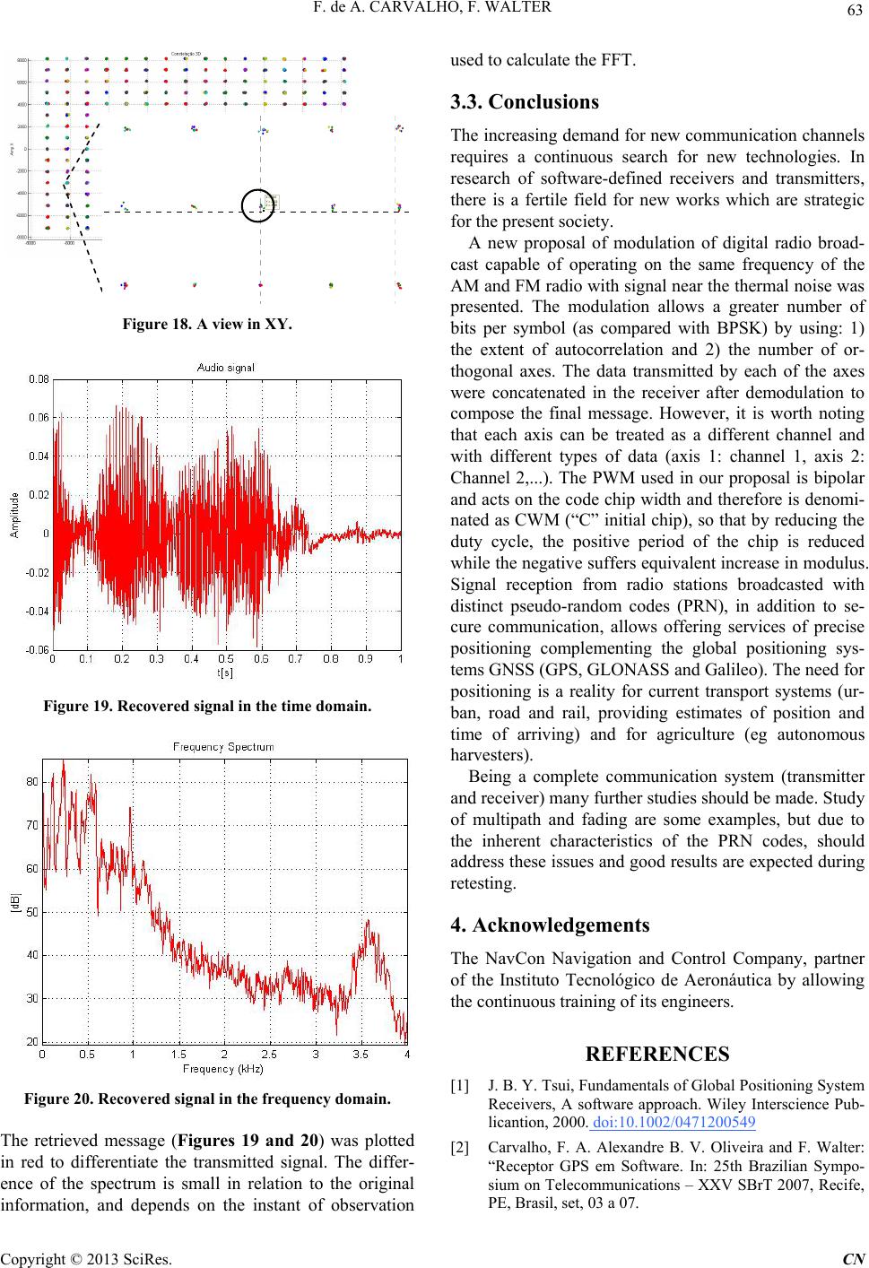 F. de A. CARVALHO, F. WALTER 63 X = 2048 Y = -2022 Z = -5135 Figure 18. A view in XY. Figure 19. Recovered signal in the time domain. Figure 20. Recovered signal in the frequency domain. The retrieved message (Figures 19 and 20) was plotted in red to differentiate the transmitted signal. The differ- ence of the spectrum is small in relation to the original information, and depends on the instant of observation used to calculate the FFT. 3.3. Conclusions The increasing demand for new communication channels requires a continuous search for new technologies. In research of software-defined receivers and transmitters, there is a fertile field for new works which are strategic for the present society. A new proposal of modulation of digital radio broad- cast capable of operating on the same frequency of the AM and FM radio with signal near the thermal noise was presented. The modulation allows a greater number of bits per symbol (as compared with BPSK) by using: 1) the extent of autocorrelation and 2) the number of or- thogonal axes. The data transmitted by each of the axes were concatenated in the receiver after demodulation to compose the final message. However, it is worth noting that each axis can be treated as a different channel and with different types of data (axis 1: channel 1, axis 2: Channel 2,...). The PWM used in our proposal is bipolar and acts on the code chip width and therefore is denomi- nated as CWM (“C” initial chip), so that by reducing the duty cycle, the positive period of the chip is reduced while the negative suffers equivalent increase in modulus. Signal reception from radio stations broadcasted with distinct pseudo-random codes (PRN), in addition to se- cure communication, allows offering services of precise positioning complementing the global positioning sys- tems GNSS (GPS, GLONASS and Galileo). The need for positioning is a reality for current transport systems (ur- ban, road and rail, providing estimates of position and time of arriving) and for agriculture (eg autonomous harvesters). Being a complete communication system (transmitter and receiver) many further studies should be made. Study of multipath and fading are some examples, but due to the inherent characteristics of the PRN codes, should address these issues and good results are expected during retesting. 4. Acknowledgements The NavCon Navigation and Control Company, partner of the Instituto Tecnológico de Aeronáutica by allowing the continuous training of its engineers. REFERENCES [1] J. B. Y. Tsui, Fundamentals of Global Positioning System Receivers, A software approach. Wiley Interscience Pub- licantion, 2000. doi:10.1002/0471200549 [2] Carvalho, F. A. Alexandre B. V. Oliveira and F. Walter: “Receptor GPS em Software. In: 25th Brazilian Sympo- sium on Telecommunications – XXV SBrT 2007, Recife, PE, Brasil, set, 03 a 07. Copyright © 2013 SciRes. CN 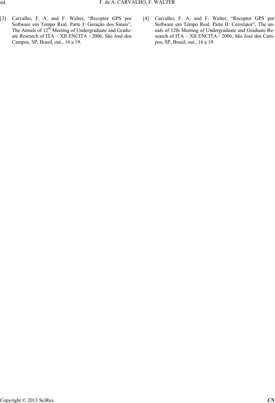 F. de A. CARVALHO, F. WALTER Copyright © 2013 SciRes. CN 64 [3] Carvalho, F. A. and F. Walter, “Receptor GPS por Software em Tempo Real. Parte I: Geração dos Sinais”, The Annals of 12th Meeting of Undergraduate and Gradu- ate Research of ITA – XII ENCITA / 2006, São José dos Campos, SP, Brasil, out., 16 a 19. [4] Carvalho, F. A. and F. Walter, “Receptor GPS por Software em Tempo Real. Parte II: Correlator”, The an- nals of 12th Meeting of Undergraduate and Graduate Re- search of ITA – XII ENCITA / 2006, São José dos Cam- pos, SP, Brasil, out., 16 a 19.
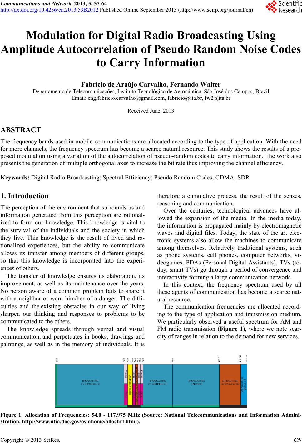
|