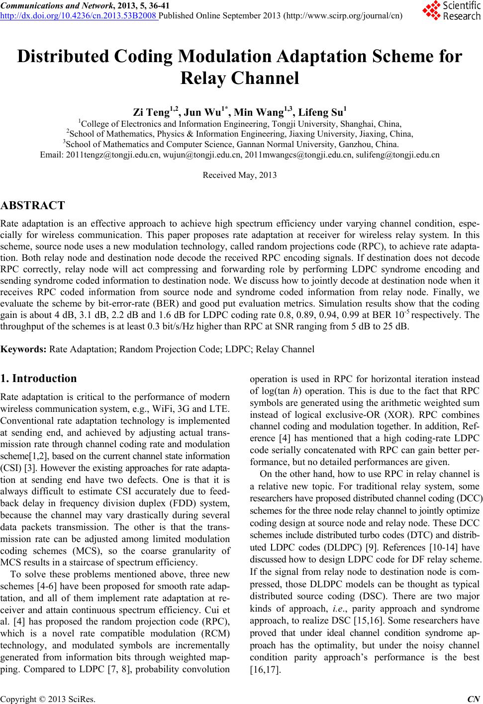
 Communications and Network, 2013, 5, 36-41 http://dx.doi.org/10.4236/cn.2013.53B2008 Published Online September 2013 (http://www.scirp.org/journal/cn) Distributed Coding Modulation Adaptation Scheme for Relay Channel Zi Te ng1,2, Jun Wu1*, Min Wang1,3, Lifeng Su1 1College of Electronics and Information Engineering, Tongji University, Shanghai, China, 2School of Mathematics, Physics & Information Engineering, Jiaxing University, Jiaxing, China, 3School of Mathematics and Computer Science, Gannan Normal University, Ganzhou, China. Email: 2011tengz@tongji.edu.cn, wujun@tongji.edu.cn, 2011mwangcs@tongji.edu.cn, sulifeng@tongji.edu.cn Received May, 2013 ABSTRACT Rate adaptation is an effective approach to achieve high spectrum efficiency under varying channel condition, espe- cially for wireless communication. This paper proposes rate adaptation at receiver for wireless relay system. In this scheme, source node uses a new modulation technology, called random projections code (RPC), to achieve rate adapta- tion. Both relay node and destination node decode the received RPC encoding signals. If destination does not decode RPC correctly, relay node will act compressing and forwarding role by performing LDPC syndrome encoding and sending syndrome coded information to destination node. We discuss how to jointly decode at destination node when it receives RPC coded information from source node and syndrome coded information from relay node. Finally, we evaluate the scheme by bit-error-rate (BER) and good put evaluation metrics. Simulation results show that the coding gain is about 4 dB, 3.1 dB, 2.2 dB and 1.6 dB for LDPC coding rate 0.8, 0.89, 0.94, 0.99 at BER 10-5 respectively. The throughput of the schemes is at least 0.3 bit/s/Hz higher than RPC at SNR ranging from 5 dB to 25 dB. Keywords: Rate Adaptation; Random Projection Code; LDPC; Relay Channel 1. Introduction Rate adaptation is critical to the performance of modern wireless communication system, e.g., WiFi, 3G and LTE. Conventional rate adaptation technology is implemented at sending end, and achieved by adjusting actual trans- mission rate through channel coding rate and modulation scheme[1,2], based on the current channel state information (CSI) [3]. However the existing approaches for rate adapta- tion at sending end have two defects. One is that it is always difficult to estimate CSI accurately due to feed- back delay in frequency division duplex (FDD) system, because the channel may vary drastically during several data packets transmission. The other is that the trans- mission rate can be adjusted among limited modulation coding schemes (MCS), so the coarse granularity of MCS results in a staircase of spectrum efficiency. To solve these problems mentioned above, three new schemes [4-6] have been proposed for smooth rate adap- tation, and all of them implement rate adaptation at re- ceiver and attain continuous spectrum efficiency. Cui et al. [4] has proposed the random projection code (RPC), which is a novel rate compatible modulation (RCM) technology, and modulated symbols are incrementally generated from information bits through weighted map- ping. Compared to LDPC [7, 8], probability convolution operation is used in RPC for horizontal iteration instead of log(tan h) operation. This is due to the fact that RPC symbols are generated using the arithmetic weighted sum instead of logical exclusive-OR (XOR). RPC combines channel coding and modulation together. In addition, Ref- erence [4] has mentioned that a high coding-rate LDPC code serially concatenated with RPC can gain better per- formance, but no detailed performances are given. On the other hand, how to use RPC in relay channel is a relative new topic. For traditional relay system, some researchers have proposed distributed channel coding (DCC) schemes for the three node relay channel to jointly optimize coding design at source node and relay node. These DCC schemes include distributed turbo codes (DTC) and distrib- uted LDPC codes (DLDPC) [9]. References [10-14] have discussed how to design LDPC code for DF relay scheme. If the signal from relay node to destination node is com- pressed, those DLDPC models can be thought as typical distributed source coding (DSC). There are two major kinds of approach, i.e., parity approach and syndrome approach, to realize DSC [15,16]. Some researchers have proved that under ideal channel condition syndrome ap- proach has the optimality, but under the noisy channel condition parity approach’s performance is the best [16,17]. C opyright © 2013 SciRes. CN 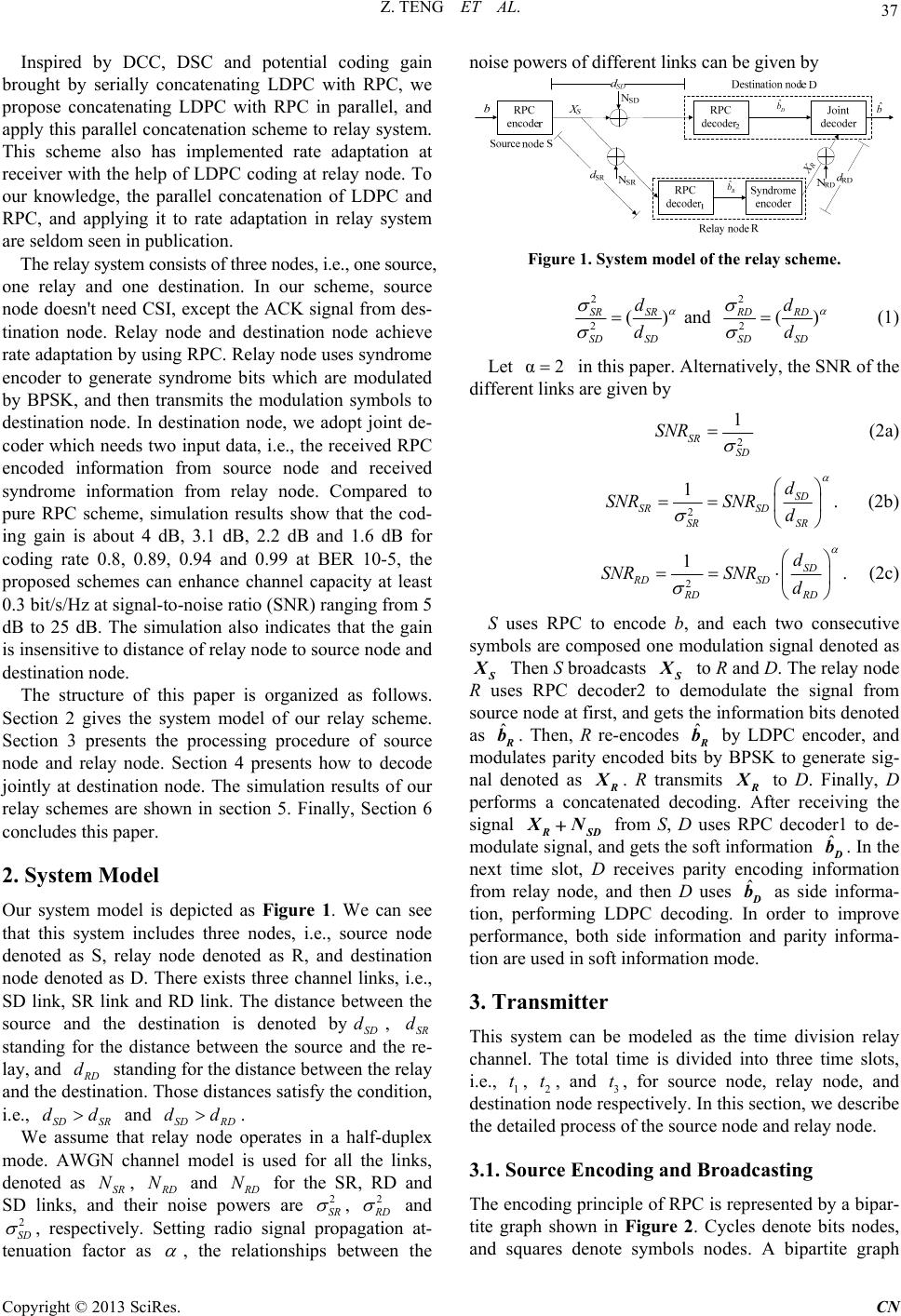 Z. TENG ET AL. 37 Inspired by DCC, DSC and potential coding gain brought by serially concatenating LDPC with RPC, we propose concatenating LDPC with RPC in parallel, and apply this parallel concatenation scheme to relay system. This scheme also has implemented rate adaptation at receiver with the help of LDPC coding at relay node. To our knowledge, the parallel concatenation of LDPC and RPC, and applying it to rate adaptation in relay system are seldom seen in publication. The relay system consists of three nodes, i.e., one source, one relay and one destination. In our scheme, source node doesn't need CSI, except the ACK signal from des- tination node. Relay node and destination node achieve rate adaptation by using RPC. Relay node uses syndrome encoder to generate syndrome bits which are modulated by BPSK, and then transmits the modulation symbols to destination node. In destination node, we adopt joint de- coder which needs two input data, i.e., the received RPC encoded information from source node and received syndrome information from relay node. Compared to pure RPC scheme, simulation results show that the cod- ing gain is about 4 dB, 3.1 dB, 2.2 dB and 1.6 dB for coding rate 0.8, 0.89, 0.94 and 0.99 at BER 10-5, the proposed schemes can enhance channel capacity at least 0.3 bit/s/Hz at signal-to-noise ratio (SNR) ranging from 5 dB to 25 dB. The simulation also indicates that the gain is insensitive to distance of relay node to source node and destination node. The structure of this paper is organized as follows. Section 2 gives the system model of our relay scheme. Section 3 presents the processing procedure of source node and relay node. Section 4 presents how to decode jointly at destination node. The simulation results of our relay schemes are shown in section 5. Finally, Section 6 concludes this paper. 2. System Model Our system model is depicted as Figure 1. We can see that this system includes three nodes, i.e., source node denoted as S, relay node denoted as R, and destination node denoted as D. There exists three channel links, i.e., SD link, SR link and RD link. The distance between the source and the destination is denoted bySD , SR standing for the distance between the source and the re- lay, and d d D standing for the distance between the relay and the destination. Those distances satisfy the condition, i.e., and . d d SD SRSD RD We assume that relay node operates in a half-duplex mode. AWGN channel model is used for all the links, denoted as SR , d dd N D and N D for the SR, RD and SD links, and their noise powers are N 2 SR , 2 D and 2 SD , respectively. Setting radio signal propagation at- tenuation factor as , the relationships between the noise powers of different links can be given by ˆ b ˆ R b ˆ D b Figure 1. System model of the relay scheme. 22 22 and() () SR SRRDRD SD SD SD SD dd dd (1) Let α2 in this paper. Alternatively, the SNR of the different links are given by 2 1 SR SD SNR (2a) 2 1. SD SR SD SR SR d SNRSNR d (2b) 2. 1SD RD SD RD RD d SNRSNR d (2c) S uses RPC to encode b, and each two consecutive symbols are composed one modulation signal denoted as Then S broadcasts to R and D. The relay node R uses RPC decoder2 to demodulate the signal from source node at first, and gets the information bits denoted as ˆ b. Then, R re-encodes ˆ b by LDPC encoder, and modulates parity encoded bits by BPSK to generate sig- nal denoted as . R transmits to D. Finally, D performs a concatenated decoding. After receiving the signal SD N from S, D uses RPC decoder1 to de- modulate signal, and gets the soft information . In the next time slot, D receives parity encoding information from relay node, and then D uses as side informa- tion, performing LDPC decoding. In order to improve performance, both side information and parity informa- tion are used in soft information mode. ˆD b ˆD b 3. Transmitter This system can be modeled as the time division relay channel. The total time is divided into three time slots, i.e., 1, 2, and 3 t, for source node, relay node, and destination node respectively. In this section, we describe the detailed process of the source node and relay node. t t 3.1. Source Encoding and Broadcasting The encoding principle of RPC is represented by a bipar- tite graph shown in Figure 2. Cycles denote bits nodes, and squares denote symbols nodes. A bipartite graph Copyright © 2013 SciRes. CN 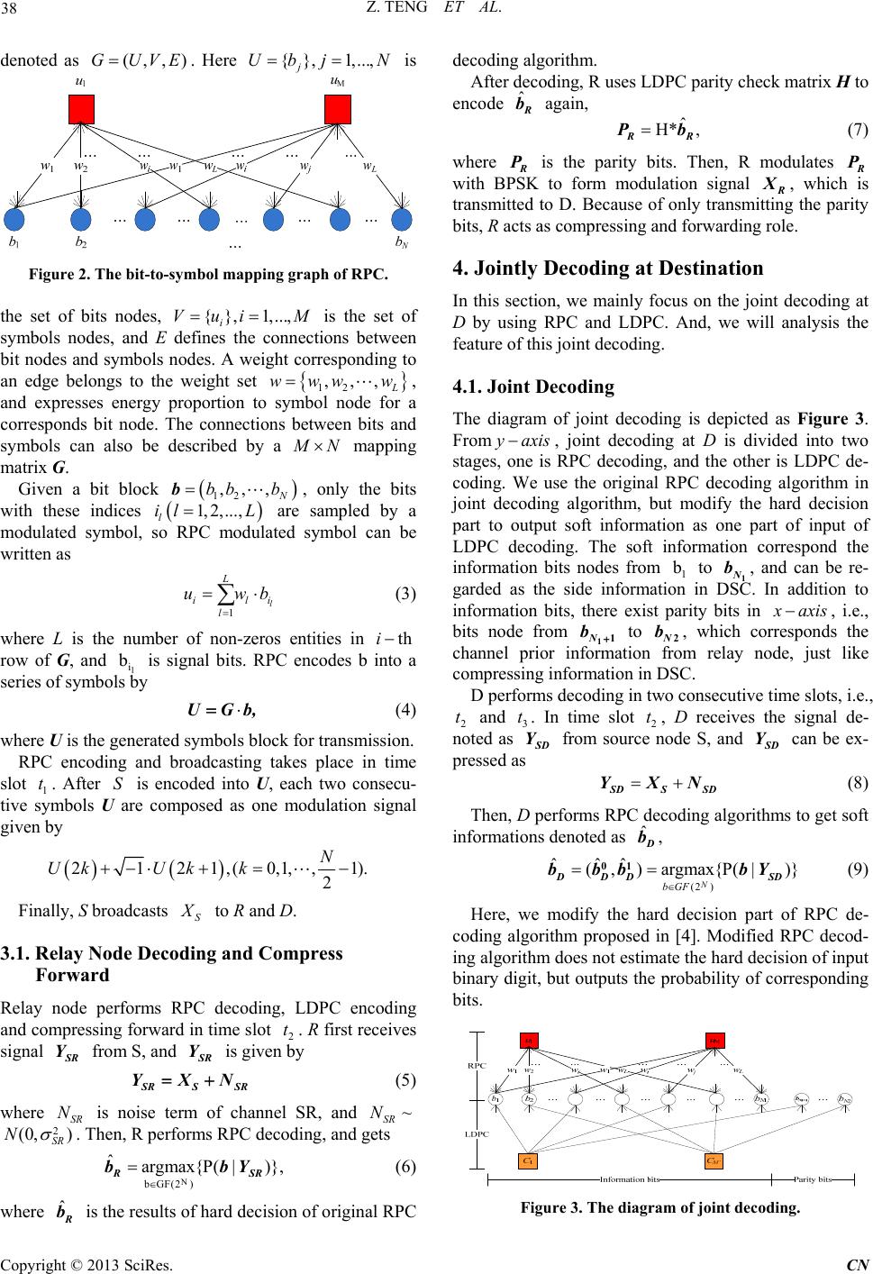 Z. TENG ET AL. 38 denoted as . Here is (,,)GUVE{ },1,..., j Ubj N Figure 2. The bit-to-symbol mapping graph of RPC. the set of bits nodes, is the set of symbols nodes, and E defines the connections between bit nodes and symbols nodes. A weight corresponding to an edge belongs to the weight set {}, 1,..., i Vui M 12 ,,, www w, and expresses energy proportion to symbol node for a corresponds bit node. The connections between bits and symbols can also be described by a N mapping matrix G. Given a bit block , only the bits with these indices l are sampled by a modulated symbol, so RPC modulated symbol can be written as 12 ,,, N bb bb 1,2,...,il L i b 1l L il l uw (3) where L is the number of non-zeros entities in thi row of G, and l i is signal bits. RPC encodes b into a series of symbols by UGb, (4) where U is the generated symbols block for transmission. RPC encoding and broadcasting takes place in time slot 1. After is encoded into U, each two consecu- tive symbols U are composed as one modulation signal given by t S 2121,(0,1,, 2 N UkUk k 1). Finally, S broadcasts S to R and D. 3.1. Relay Node Decoding and Compress Forward Relay node performs RPC decoding, LDPC encoding and compressing forward in time slot 2. R first receives signal t R Y from S, and R Y is given by RSS YXN R (5) where is noise term of channel SR, and SR N 2) SR ~ SR N (0,N . Then, R performs RPC decoding, and gets N bGF(2 ) ˆargmax{P( |)}, R bb SR Y (6) where ˆ b is the results of hard decision of original RPC decoding algorithm. After decoding, R uses LDPC parity check matrix H to encode ˆ b again, ˆ H* , R Pb (7) where P is the parity bits. Then, R modulates P with BPSK to form modulation signal , which is transmitted to D. Because of only transmitting the parity bits, R acts as compressing and forwarding role. 4. Jointly Decoding at Destination In this section, we mainly focus on the joint decoding at D by using RPC and LDPC. And, we will analysis the feature of this joint decoding. 4.1. Joint Decoding The diagram of joint decoding is depicted as Figure 3. From axis , joint decoding at D is divided into two stages, one is RPC decoding, and the other is LDPC de- coding. We use the original RPC decoding algorithm in joint decoding algorithm, but modify the hard decision part to output soft information as one part of input of LDPC decoding. The soft information correspond the information bits nodes from 1 to 1 N, and can be re- garded as the side information in DSC. In addition to information bits, there exist parity bits in b axis , i.e., bits node from 11N b to 2N, which corresponds the channel prior information from relay node, just like compressing information in DSC. b D performs decoding in two consecutive time slots, i.e., 2 and . In time slot 2, D receives the signal de- noted as t3 t t D Y from source node S, and D Y can be ex- pressed as DSS YXN D (8) Then, D performs RPC decoding algorithms to get soft informations denoted as , ˆD b (2 ) ˆˆˆ (, )argmax{P(|)} N bGF 01 DDD SD bbb bY (9) Here, we modify the hard decision part of RPC de- coding algorithm proposed in [4]. Modified RPC decod- ing algorithm does not estimate the hard decision of input binary digit, but outputs the probability of corresponding bits. Figure 3. The diagram of joint decoding. Copyright © 2013 SciRes. CN 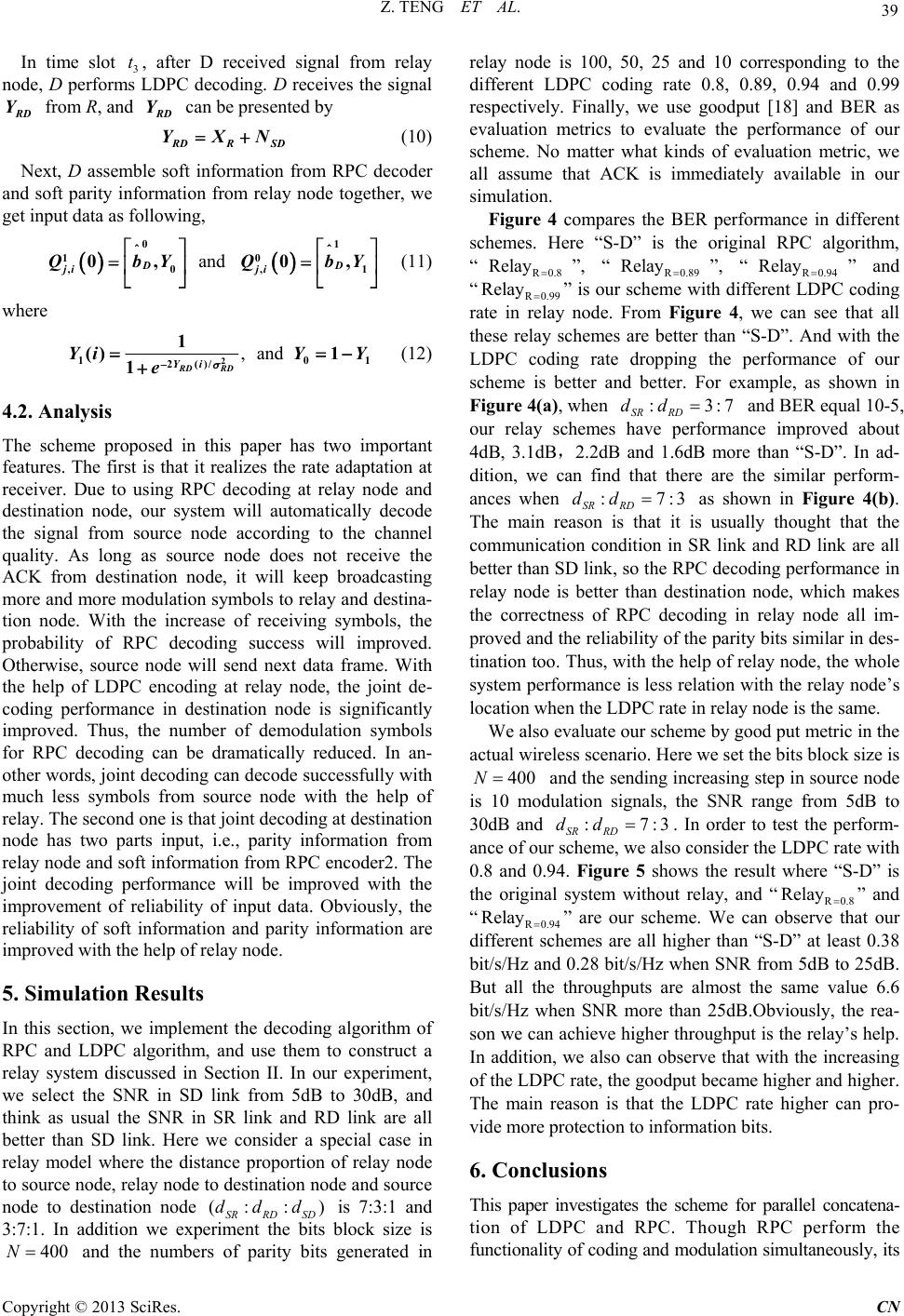 Z. TENG ET AL. 39 In time slot 3, after D received signal from relay node, D performs LDPC decoding. D receives the signal t D Y from R, and D Y can be presented by DRS YXN D 1 1 Y (10) Next, D assemble soft information from RPC decoder and soft parity information from relay node together, we get input data as following, and 0 0 1,0, 0, 0, DD ji ji QbYQb (11) where , and 2 10 2()/ 1 () 1 1RD RD Yi YiY Y e ) : 1 (12) 4.2. Analysis The scheme proposed in this paper has two important features. The first is that it realizes the rate adaptation at receiver. Due to using RPC decoding at relay node and destination node, our system will automatically decode the signal from source node according to the channel quality. As long as source node does not receive the ACK from destination node, it will keep broadcasting more and more modulation symbols to relay and destina- tion node. With the increase of receiving symbols, the probability of RPC decoding success will improved. Otherwise, source node will send next data frame. With the help of LDPC encoding at relay node, the joint de- coding performance in destination node is significantly improved. Thus, the number of demodulation symbols for RPC decoding can be dramatically reduced. In an- other words, joint decoding can decode successfully with much less symbols from source node with the help of relay. The second one is that joint decoding at destination node has two parts input, i.e., parity information from relay node and soft information from RPC encoder2. The joint decoding performance will be improved with the improvement of reliability of input data. Obviously, the reliability of soft information and parity information are improved with the help of relay node. 5. Simulation Results In this section, we implement the decoding algorithm of RPC and LDPC algorithm, and use them to construct a relay system discussed in Section II. In our experiment, we select the SNR in SD link from 5dB to 30dB, and think as usual the SNR in SR link and RD link are all better than SD link. Here we consider a special case in relay model where the distance proportion of relay node to source node, relay node to destination node and source node to destination node is 7:3:1 and 3:7:1. In addition we experiment the bits block size is and the numbers of parity bits generated in relay node is 100, 50, 25 and 10 corresponding to the different LDPC coding rate 0.8, 0.89, 0.94 and 0.99 respectively. Finally, we use goodput [18] and BER as evaluation metrics to evaluate the performance of our scheme. No matter what kinds of evaluation metric, we all assume that ACK is immediately available in our simulation. (: : SR RD SD ddd 400N Figure 4 compares the BER performance in different schemes. Here “S-D” is the original RPC algorithm, “”, “R0.89 ”, “R0.94 ” and “R0.99 Re ” is our scheme with different LDPC coding rate in relay node. From Figure 4, we can see that all these relay schemes are better than “S-D”. And with the LDPC coding rate dropping the performance of our scheme is better and better. For example, as shown in Figure 4(a), when SR RD and BER equal 10-5, our relay schemes have performance improved about 4dB, 3.1dB,2.2dB and 1.6dB more than “S-D”. In ad- dition, we can find that there are the similar perform- ances when SR RD R0.8 Relay lay Relay :dd :7:3 Relay 73 dd as shown in Figure 4(b). The main reason is that it is usually thought that the communication condition in SR link and RD link are all better than SD link, so the RPC decoding performance in relay node is better than destination node, which makes the correctness of RPC decoding in relay node all im- proved and the reliability of the parity bits similar in des- tination too. Thus, with the help of relay node, the whole system performance is less relation with the relay node’s location when the LDPC rate in relay node is the same. We also evaluate our scheme by good put metric in the actual wireless scenario. Here we set the bits block size is 400N and the sending increasing step in source node is 10 modulation signals, the SNR range from 5dB to 30dB and :7 SR RD dd :3 . In order to test the perform- ance of our scheme, we also consider the LDPC rate with 0.8 and 0.94. Figure 5 shows the result where “S-D” is the original system without relay, and “R0.8 Re ” and “R0.94 Re ” are our scheme. We can observe that our different schemes are all higher than “S-D” at least 0.38 bit/s/Hz and 0.28 bit/s/Hz when SNR from 5dB to 25dB. But all the throughputs are almost the same value 6.6 bit/s/Hz when SNR more than 25dB.Obviously, the rea- son we can achieve higher throughput is the relay’s help. In addition, we also can observe that with the increasing of the LDPC rate, the goodput became higher and higher. The main reason is that the LDPC rate higher can pro- vide more protection to information bits. lay lay 6. Conclusions This paper investigates the scheme for parallel concatena- tion of LDPC and RPC. Though RPC perform the functionality of coding and modulation simultaneously, its Copyright © 2013 SciRes. CN 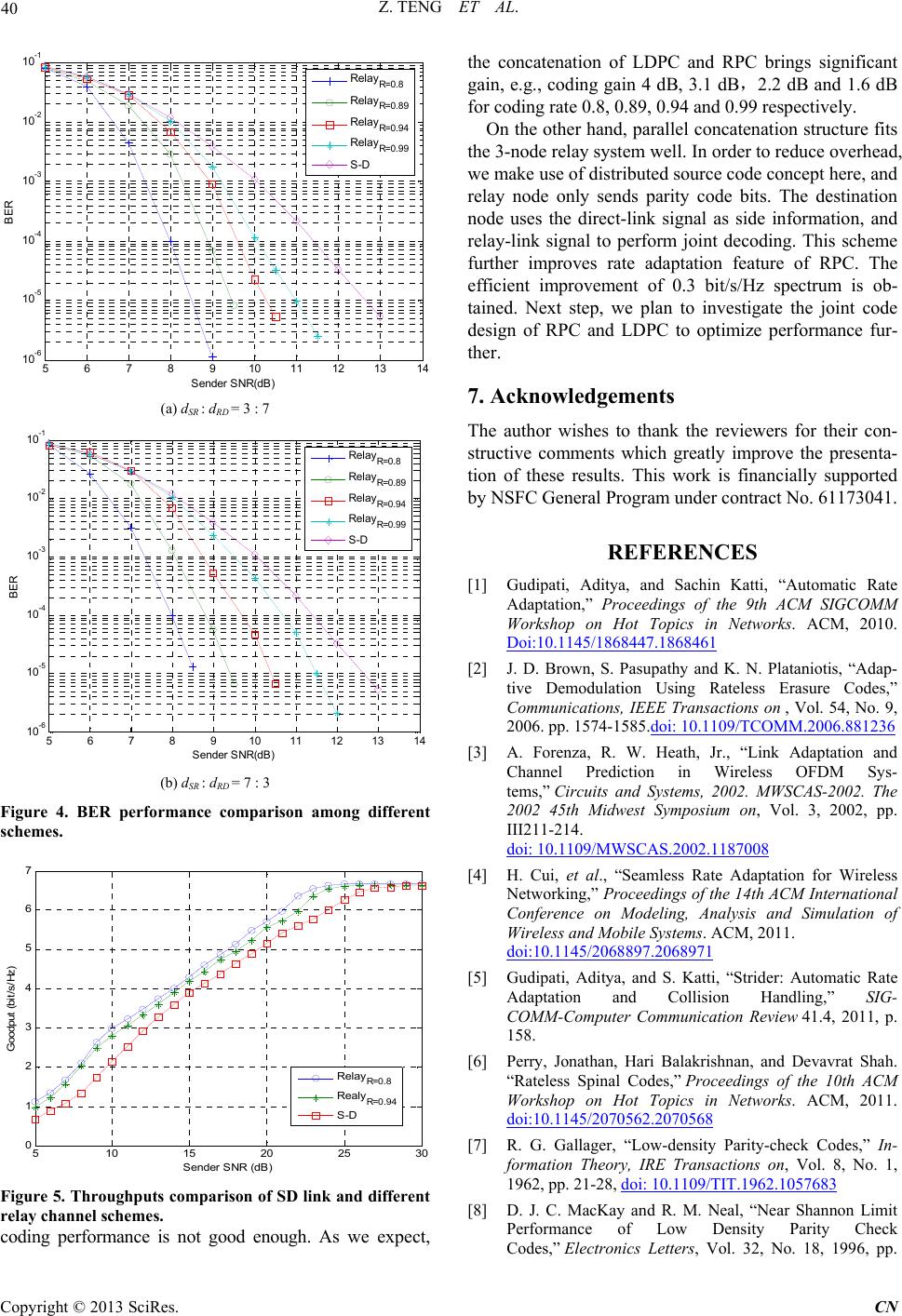 Z. TENG ET AL. 40 5678910 11 12 1314 10 -6 10 -5 10 -4 10 -3 10 -2 10 -1 S ender S NR(dB) BER Rel a y R=0.8 Rel a y R=0.89 Rel a y R=0.94 Rel a y R=0.99 S-D (a) dSR : dRD = 3 : 7 5678910 11 12 13 14 10-6 10-5 10-4 10-3 10-2 10-1 S end er SNR(dB ) BER Rel ay R=0.8 Rel ay R=0.89 Rel ay R=0.94 Rel ay R=0.99 S-D (b) dSR : dRD = 7 : 3 Figure 4. BER performance comparison among different schemes. 510 15 20 25 30 0 1 2 3 4 5 6 7 Sender SNR (dB) Goodput (bit/s/Hz) Rel ay R=0.8 Realy R=0.94 S-D Figure 5. Throughputs co mparison of SD link and different relay channel schemes. coding performance is not good enough. As we expect, the concatenation of LDPC and RPC brings significant gain, e.g., coding gain 4 dB, 3.1 dB,2.2 dB and 1.6 dB for coding rate 0.8, 0.89, 0.94 and 0.99 respectively. On the other hand, parallel concatenation structure fits the 3-node relay system well. In order to reduce overhead, we make use of distributed source code concept here, and relay node only sends parity code bits. The destination node uses the direct-link signal as side information, and relay-link signal to perform joint decoding. This scheme further improves rate adaptation feature of RPC. The efficient improvement of 0.3 bit/s/Hz spectrum is ob- tained. Next step, we plan to investigate the joint code design of RPC and LDPC to optimize performance fur- ther. 7. Acknowledgements The author wishes to thank the reviewers for their con- structive comments which greatly improve the presenta- tion of these results. This work is financially supported by NSFC General Program under contract No. 61173041. REFERENCES [1] Gudipati, Aditya, and Sachin Katti, “Automatic Rate Adaptation,” Proceedings of the 9th ACM SIGCOMM Workshop on Hot Topics in Networks. ACM, 2010. Doi:10.1145/1868447.1868461 [2] J. D. Brown, S. Pasupathy and K. N. Plataniotis, “Adap- tive Demodulation Using Rateless Erasure Codes,” Communications, IEEE Transactions on , Vol. 54, No. 9, 2006. pp. 1574-1585.doi: 10.1109/TCOMM.2006.881236 [3] A. Forenza, R. W. Heath, Jr., “Link Adaptation and Channel Prediction in Wireless OFDM Sys- tems,” Circuits and Systems, 2002. MWSCAS-2002. The 2002 45th Midwest Symposium on, Vol. 3, 2002, pp. III211-214. doi: 10.1109/MWSCAS.2002.1187008 [4] H. Cui, et al., “Seamless Rate Adaptation for Wireless Networking,” Proceedings of the 14th ACM International Conference on Modeling, Analysis and Simulation of Wireless and Mobile Systems. ACM, 2011. doi:10.1145/2068897.2068971 [5] Gudipati, Aditya, and S. Katti, “Strider: Automatic Rate Adaptation and Collision Handling,” SIG- COMM-Computer Communication Review 41.4, 2011, p. 158. [6] Perry, Jonathan, Hari Balakrishnan, and Devavrat Shah. “Rateless Spinal Codes,” Proceedings of the 10th ACM Workshop on Hot Topics in Networks. ACM, 2011. doi:10.1145/2070562.2070568 [7] R. G. Gallager, “Low-density Parity-check Codes,” In- formation Theory, IRE Transactions on, Vol. 8, No. 1, 1962, pp. 21-28, doi: 10.1109/TIT.1962.1057683 [8] D. J. C. MacKay and R. M. Neal, “Near Shannon Limit Performance of Low Density Parity Check Codes,” Electronics Letters, Vol. 32, No. 18, 1996, pp. Copyright © 2013 SciRes. CN 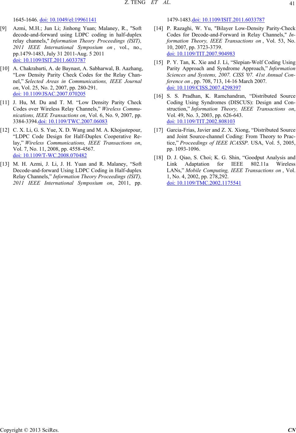 Z. TENG ET AL. Copyright © 2013 SciRes. CN 41 1645-1646. doi: 10.1049/el:19961141 [9] Azmi, M.H.; Jun Li; Jinhong Yuan; Malaney, R., "Soft decode-and-forward using LDPC coding in half-duplex relay channels," Information Theory Proceedings (ISIT), 2011 IEEE International Symposium on , vol., no., pp.1479-1483, July 31 2011-Aug. 5 2011 doi: 10.1109/ISIT.2011.6033787 [10] A. Chakrabarti, A. de Baynast, A. Sabharwal, B. Aazhang, “Low Density Parity Check Codes for the Relay Chan- nel,” Selected Areas in Communications, IEEE Journal on, Vol. 25, No. 2, 2007, pp. 280-291. doi: 10.1109/JSAC.2007.070205 [11] J. Hu, M. Du and T. M. “Low Density Parity Check Codes over Wireless Relay Channels,” Wireless Commu- nications, IEEE Transactions on, Vol. 6, No. 9, 2007, pp. 3384-3394.doi: 10.1109/TWC.2007.06083 [12] C. X. Li, G. S. Yue, X. D. Wang and M. A. Khojastepour, “LDPC Code Design for Half-Duplex Cooperative Re- lay,” Wireless Communications, IEEE Transactions on, Vol. 7, No. 11, 2008, pp. 4558-4567. doi: 10.1109/T-WC.2008.070482 [13] M. H. Azmi, J. Li, J. H. Yuan and R. Malaney, “Soft Decode-and-forward Using LDPC Coding in Half-duplex Relay Channels,” Information Theory Proceedings (ISIT), 2011 IEEE International Symposium on, 2011, pp. 1479-1483.doi: 10.1109/ISIT.2011.6033787 [14] P. Razaghi, W. Yu, "Bilayer Low-Density Parity-Check Codes for Decode-and-Forward in Relay Channels," In- formation Theory, IEEE Transactions on , Vol. 53, No. 10, 2007, pp. 3723-3739. doi: 10.1109/TIT.2007.904983 [15] P. Y. Tan, K. Xie and J. Li, “Slepian-Wolf Coding Using Parity Approach and Syndrome Approach,” Information Sciences and Systems, 2007. CISS '07. 41st Annual Con- ference on , pp. 708, 713, 14-16 March 2007. doi: 10.1109/CISS.2007.4298397 [16] S. S. Pradhan, K. Ramchandran, “Distributed Source Coding Using Syndromes (DISCUS): Design and Con- struction,” Information Theory, IEEE Transactions on, Vol. 49, No. 3, 2003, pp. 626-643. doi: 10.1109/TIT.2002.808103 [17] Garcia-Frias, Javier and Z. X. Xiong, “Distributed Source and Joint Source-channel Coding: From Theory to Prac- tice,” Proceedings of IEEE ICASSP. USA, Vol. 5, 2005, pp. 1093-1096. [18] D. J. Qiao, S. Choi; K. G. Shin, “Goodput Analysis and Link Adaptation for IEEE 802.11a Wireless LANs,” Mobile Computing, IEEE Transactions on , Vol. 1, No. 4, 2002, pp. 278,292. doi: 10.1109/TMC.2002.1175541
|