 Energy and Power Engineering, 2013, 5, 717-721 doi:10.4236/epe.2013.54B139 Published Online July 2013 (http://www.scirp.org/journal/epe) Emergency Control Strategy Based on Multi-agent Theory under Blackout* Bin Sun1, Ming Liu1, Luofang Zhu1, Nian Liu2, X ia o yan Qiu2, Zhe Zhuang2 1Guizhou Power Grid Corporation of Dispatch Control Center, Guiyang, Guizhou, China 2School of Electrical Engineering and Information Sichuan University, Chengdu, China Email: zhuangzhe3000@vip.qq.com, cd_qxy@sina.com Received March, 2013 ABSTRACT The multi-agent theory is in troduced and applied in the way to strike the control amount of emergency con trol accord- ing to stability margin, based on which an emergency control strategy of the power system is presented. The multi-agent control structure which is put fo rward in this article has three layers: system agent, areal agent and local agents. System agent sends controlling execution signal to the load-local agent according to the position and the amount of load shed- ding upload from areal agent; The areal agent judges whether the power system is stable by monitoring and analyzing the maximum relative power angle. In the condition of instability, determines the position of load-shedding, and the optimal amount of load-shedding according to the stability margin based on the corrected transient energy function, upload control amount to system agent; local-generator agent is mainly used for real-time monitoring the power angle of generator sets and uploading it to the areal agency, local-loads agent control load by receiving the control signal from system agent. Simulations on IEEE39 system show that the proposed control strategy improves th e system stability. Keywords: Multi-agent; Corrected Transient Energy Function; Emergency Control; Stability Margin 1. Introduction With the development of economy, the growing of the load demand, the increase of grid scale, the continuous development of the regional interconnection and long- distance transmission of electricity markets, the grid is long-running at the limit state, the stability margin is getting smaller and smaller. When the grid is affected by the large disturbance, it may cause grid instability, and longtime power off, even network splitting [1-4]. Emer- gency control can reduced the extent of the damage to a minimum after the grid is affected by the large distur- bance, so, it is an important measure to maintain system stability [5-8]. In the field of artificial intelligence, Multi-Agent has good characters of autonomy, reactivity, initiative and social. It is contributing to emergency control to change from “Off-line pre-decision-making, real-time match.” to “Real-time decision-making, real-time execution”. Lit- erature [9] applies the Multi-agent technology to the power system black start. Reference [10] proposed the method changed from centralized management to dis- tributed coordinated management through the Multi- Agent system approach. Article [11] shows the Multi- criteria hierarchical emergency control system is condu- cive to independent autonomous effect between the lay- ers. In the literature, multi-agent theory is introduced into the way based on the stability margin to strike control amount of the emergency control, proposes emergency control strategy based on multi-agent technology[12-15], the multi-agent control organizational structure has three layers: system agent, areal agent and local agents. 2. Multi-agent Control Organizational Structure The multi-agent control org anization al structu re has three layers: system agent, areal agent and local agents. The primary responsibility of system agency is receiving the data of load shedding position and the amount of load shedding an d to issue a contro l signal to local load Agent; the main responsibility of areal agent is to received and processed the data quickly and accurately, and to deter- mine load shedding position and the amount of load shedding; the primary responsibility of local agency is to real-time detecting the state of each generator group, to transmute real-time testing data is to the regional agency, and to control the load. The multi-agent control organ- izational structur e is as shown in Figure 1. *The project supported by GuiZhou Power Grid Corporation (12H- 0594),Technology Project of Science & Technology Department of Si- chuan Province (No.2011GZ0036 ) Copyright © 2013 SciRes. EPE 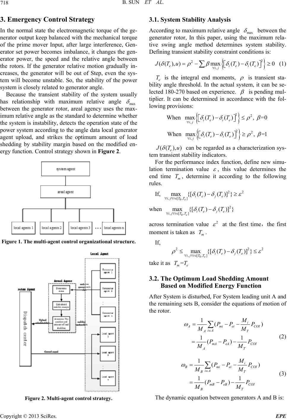 B. SUN ET AL. 718 3. Emergency Control Strategy In the normal state the electromagnetic torque of the ge- nerator output keep balanced with the mechanical torque of the prime mover Input, after large interference, Gen- erator set power becomes imbalance, it changes the gen- erator power, the speed and the relative angle between the rotors. If the generator relative motion gradually in- creases, the generator will be out of Step, even the sys- tem will become unstable. So, the stability of the power system is closely related to generator angle. Because the transient stability of the system usually has relationship with maximum relative angle max between the generator rotor, areal agency uses the max- imum relative angle as the standard to determine whether the system is instability, detects the op eration state of the power system according to the angle data local generator agent upload, and strikes the optimum amount of load shedding by stability margin based on the modified en- ergy function. Control strategy shown in Figure 2. Figure 1. The multi-agent control organizational structure. Figure 2. Multi-agent control strategy. 3.1. System Stability Analysis According to maximum relative angle max between the generator rotor, In this paper, using the maximum rela- tive swing angle method determines system stability. Defining transient stability constraint conditions is: 2 2 , (( ),)max( )( )0 eiei ij JTuT T e (1) e is the integral end moments, T is transient sta- bility angle threshold. In the actual system, it can be se- lected 180-270 based on experience. is pending mul- tiplier. It can be determined in accordance with the fol- lowing provisions: When 22 , max()(), =0 ie ie ij TT When 22 , max()(), =1 ie ie ij TT (( ),) e Tu can be regarded as a characterization sys- tem transient stability indicators. For the performance index function, define new simu- lation termination value , this value determines the end time , determine it according to the following rules. m T If, 0 22 ,[,] max{[ ( )( )]} eie je ijtT TTT when 0 2 ,[,] max{[()()] } eie je ijtT TTT across termination value 2 at the first time,the first moment is taken as . m T If, 0 22 ,[,] max{[ ( )( )]} eie je ijtT TTT 2 take it as = me TT 3.2. The Optimum Load Shedding Amount Based on Modified Energy Function After System is disturbed, For System leading unit A and the remaining sets B, consider the eq uations of motion of the rotor. 1() 11 () i Amiei iA AT mA eACOI AT M PP P MM PP P MM COI (2) 1() 11 () i mi eiCOI iA B mB eBCOI BT M PP P MM PP P MM T (3) The dynamic equation betwee n generators A and B is: Copyright © 2013 SciRes. EPE 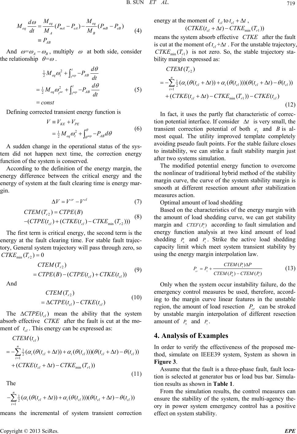 B. SUN ET AL. 719 ()( eq eq eqmA eAmB eB AB AB MM d) PP PP dt MM P (4) And =AB , multiply at both side, consider the relationship = . 2 1 2 2 1 2 sep ae sep t eq tAB t t eq AB tt d MP dt d MP dt const (5) Defining corrected transient energy function is 2 1 2sep KE PE eq tAB VV V Pd (6) A sudden change in the operational status of the sys- tem did not happen next time, the correction energy function of the system is conserved. According to the definition of the energy margin, the energy difference between the critical energy and the energy of system at the fault clearing time is energy mar- gin. cr cl VV V (7) 2 min 2 () () (()(() () r cl clr CTEM TCTPE B CTPE tCTKE tCTKET )) (8) The first term is critical energy, the second term is the energy at the fault clearing time. For stable fault trajec- tory, General system trajectory will pass through zero, so min 2 ()0 r CTKET 2 () () (()( )) r cl cl CTEM T CTPEBCTPE tCTKE t (9) And 2 () () () r cl cl CTEM T CTPE tCTKE t (10) The mean the ability that the system absorb effective after the fault is cut at the mo- ment of . This energy can be expressed as: () cl CTPE tCT cl tKE 1 2 1 min 1 () ((())(()))(()( (() ()) cl n i cli clclcl i cl r CTEM t ttt ttt CTKE ttCTKET )) (11) The 1 2 1(( ())( ()))( ()()) n i cli clclcl i tttttt means the incremental of system transient correction energy at the moment of to , cl ttcl tt )CTKEmin1 (( ( cl r CTKE tT)) means the system absorb effective after the fault is cut at the moment ofCTKE + cl tt . For the unstable trajectory, min1 is not zero. So, the stable trajectory sta- bility margin expressed as: () r CTKE T 2 1 2 1 min 1 () ((())(()))(()( (()())() r n i cli clclcl i clr cl CTEM T tttttt CTKE ttCTKETCTKE t )) (12) In fact, it uses the partly flat characteristic of correc- tion potential interface. If consider is very small, the transient correction potential of both 1 e and is al- most equal. The utility improved template completely avoiding pseudo fault points. For the stable failure closes to instability, we can strike a fault stability margin just after two systems simulation. tB The modified potential energy function to overcome the nonlinear of traditiona l hybrid method of the stability margin curve, the curve of the system stability margin is smooth at different resection amount after stabilization measures action. Optimal amount of load shedding Based on the characteristics of the energy margin with the amount of load shedding curve, we can get stability margin and 1 according to fault simulation and energy function analysis at two kind amount of load shedding 0 and 1. Strike the active load shedding capacity limit which meet system transient stability by using the energy margin interpolation law. ()CTEF P PP 1 1 01 () () () cr CTEMPP PP CTEM PCTEM P (13) Only when the system occur instability failure, do the emergency control measures be used, therefore, accord- ing to the margin curve linear features in the unstable region, the amount of load resection cr can be stroked by unstable margin interpolation of different resection amount o f and . P 0 P1 P 4. Analysis of Examples In order to verify the effectiveness of the proposed me- thod, simulate on IEEE39 system, System as shown in Figure 3. Assume that the fault is a three-phase fault, fau lt loca- tion is selected at generator bus or load bus bar. Simula- tion results as shown in Table 1. From the simulation results, the control measures can ensure the stability of the system, the multi-agency the- ory in power system emergency control has a positive effect on system stability. Copyright © 2013 SciRes. EPE  B. SUN ET AL. Copyright © 2013 SciRes. EPE 720 Figure 3. 10, 39-bus system diagram. Table 1 result of load shedding scheme in IEEE39 sy ste m. Fault location Resection line Critical clearing time /s Actual fault clearing time /s Shutdown generator Load shedding program (Load node number, The amount of load shedding) results of the control measures 3 3-4 0.27~0.28 0.29 37 18;-1.0324-j0.2765 Stable 6 5-6 0.16~0.17 0.24 31 4;-0.6244-j0.2856 Stable 10 10-13 0.21~0.22 0.24 32,39 12;-0.4332-j0.1004 Stable 15 14-15 0.19~0.22 0.23 32,37 15;-0.7420-j0.2519 Stable 17 17-18 0.22~0.23 0.33 37 18;-1.2654-j0.5750 Stable 23 22-23 0.24~0.25 0.28 36 22;-0.8861-j0.4021 Stable 5. Conclusions In the literature, multi-agent theory is introd uced into the way based on the stability margin to strike control amount of the emergency control, proposes emergency control strategy based on multi-agent technology, the multi-agent control organizational structure has three layers. It is achieved systems state data real-time interac- tion, show multi-Agen t has good ch aracters of autonomy, reactivity, initiative and social. It is contributing to emergency control to change from “Off-line pre-deci- sion-making, real-time match.” to “Real-time decision- making, real-time execution”. Simulations on IEEE39 system show that the proposed control strategy improves the system stability. REFERENCES [1] D. Ruiz-Vega and M. Pavella, “A Comprehensive Ap- proach to Transient Stability Control Part I—Near Opti- mal Preventive Control, Part II—Open Loop Emergency Control,” IEEE Transactions on Power System, 2003, Vol. 18, No. 4, pp. 1446-1460. doi:10.1109/TPWRS.2003.818708 [2] D. Gan, R. J. Thomas and R. D. Zimmerman, Stabil- ity-constrained Optimal Power Flow,” IEEE Transactions on Power Systems, Vol. 15, No. 2, 2000, pp. 535-540.doi:10.1109/59.867137 [3] X. Y. Li and L. Li, “Survey of the Emergency Control in Power System,” Automation of Electric Power Systems, Vol. 24, No. 9, 2000, pp. 5-11. [4] L. Li, Z. Yan, Z. X. Wang, et al., “Emergency Control Strategies Based on the Model of the A-S-C,” Automation of Electric Power Systems, Vol. 33, No. 5, 2009, pp. 7-11. [5] Z. Chen, W. J. Du, H. F. Wang, et al., “Framework of Multi-agent System in Post-emergency Voltage Stability Control,” Automation of Electric Power Systems, Vol. 30, No. 12, 2006, pp. 33-37. [6] M. J. Zhang, L. X. Cao, J. W. Li, et al., “Multi-agent System for Voltage/VAR Optimization Considering Multi-regional Power System,” Automation of Electric  B. SUN ET AL. 721 Power Systems, Vol. 28, No. 17, 2004, pp. 33-37. [7] A. Ian and M. A. Pai. Hiskens, “Trajectory Sensitivity Analysis of Hybrid System,” IEEE Transactions on Power System, Vol. 47, No. 2, 2002, pp. 204-220. [8] B. Tony and M. A. Pai. Nguyen, “Dynamic Secu- rity-Constrained Rescheduling of Power Systems Using Trajectory Sensitivities,” IEEE Transactions on Power System, Vol. 18, No. 2, 2003, pp. 848-854. doi:10.1109/TPWRS.2003.811002 [9] T. Nagata and H. Sasaki, “A Multi-agent Approach to Power System Restoration,” IEEE Transactions on Power Systems, Vol. 17, No. 2, 2002, pp. 457-462. doi:10.1109/TPWRS.2002.1007918 [10] C. S. Wang and X. Y. Yu, “Distributed Coordinative Emergency Control Based on Multi-agent System,” Power System Technology, Vol. 28, No. 3, 2004, pp. 1-5. [11] L. F. Li, Z. M. Wang, J. L. Yu, et al., “Hierarchical Sys- tem with Multi-criterion for Voltage Emergency Control Based on MAS,” Electric Power Automation Equipment, Vol. 26, No. 5, 2006, pp. 5-10. [12] Z. D. Bi, J. Q. Wang, et al., “A Fast Shedding Algorithm Based On Integral Sensitivity,” Power System Technology, Vol. 26, No. 8, 2002, pp. 4-7, 43. [13] Z. H. Feng and S. X. Zhou, “Determination of Voltage Collapse Areas in Large Scale Power System,” Proceed- ings of the CSEE, Vol. 17, No. 3, 1997, pp. 21-26. [14] J. Q. Sun, D. Z. Fang and T. S. Chung, “Optimal Power Flow with Transient Stability Constraints,” Proceedings of the CSEE, Vol. 25, No. 12, 2005, pp. 12-17. [15] Daniel Ruiz2Vega and Mania Pavella, “A Comprehensive Approach to Transient Stability Control Part I-N Ear Optimal Preventive Control Part II-Open Loop Emer- gency Control,” IEEE Transactions on Power Systems, Vol. 18, No. 4, 2003, pp. 1446-1460. doi:10.1109/TPWRS.2003.818708 Copyright © 2013 SciRes. EPE
|